Brasch GSE Generation 2 User manual
GSE Generation 2
Installation / Operation Manual
Brasch Environmental Technologies, LLC
1 0 Long Road, Suite 101
Chesterfield, Missouri 63005
31 -291-0 0
www.braschenvtech.com

Table of Contents
Introduction...................................................................................................................................
General Description..................................................................................................................
Features and Benefits..............................................................................................................5
Technical Specifications................................................................................................................6
Product Specifications..............................................................................................................6
Target Gas Specifications.........................................................................................................7
Carbon Monoxide.................................................................................................................7
Nitrogen Dioxide...................................................................................................................7
Description of Front Panel Indicators.......................................................................................8
Front Panel Indicators..........................................................................................................8
Operation Safety Notice................................................................................................................9
Types of Notices.......................................................................................................................9
Quick Start Guide.......................................................................................................................10
Step 1 – Mounting..................................................................................................................10
Step 2 – Input Wiring..............................................................................................................10
Step 3 – Remote Transmitter Wiring......................................................................................11
Step – Relay Wiring.............................................................................................................12
Step 5 – External Alarms........................................................................................................12
Step 6 – Applying Power........................................................................................................12
Step 7 – Self-Test Mode.........................................................................................................13
Installation...................................................................................................................................1
Mounting the Detector............................................................................................................1
Connecting the Power Supply................................................................................................15
Connecting the Remote Transmitters.....................................................................................17
Connecting the Ventilation System.........................................................................................17
Connecting the External Alarm...............................................................................................18
Connecting the Voltage or Current Proportional Output........................................................18
Applying Power For the First Time.........................................................................................18
Using the Self-Test Feature....................................................................................................19
Typical Installation Diagrams..................................................................................................20
Operation....................................................................................................................................23
How the Detector Senses the Target Gas..............................................................................23
How the Detector Controls the Ventilation Equipment...........................................................23
Low Alert.............................................................................................................................23
High Alert............................................................................................................................23
Alarm..................................................................................................................................2
Proportional Output............................................................................................................2
Manual Fan Activation........................................................................................................2
Factory Default Settings.........................................................................................................25
Adjusting the Settings.............................................................................................................26
Sensor Number..................................................................................................................26
Active Sensors...................................................................................................................26
IOM01
Rev 1.0 – December 22, 2020 2

Active Zones.......................................................................................................................26
Zone Delay.........................................................................................................................26
Zone Alert...........................................................................................................................26
High Alert Relay Operation.................................................................................................27
Fan Speed..........................................................................................................................27
Proportional Output............................................................................................................27
Using the Proportional Outputs..............................................................................................27
Obtaining the Best Operation.................................................................................................28
Carbon Monoxide and/or Nitrogen Dioxide Detectors.......................................................28
Maintenance...............................................................................................................................30
Testing the Response to the Target Gas................................................................................30
Carbon Monoxide and/or Nitrogen Dioxide Detectors.......................................................30
Replacing the Sensor.............................................................................................................31
Suggested Repair Parts.........................................................................................................32
Troubleshooting..........................................................................................................................33
Error Codes............................................................................................................................33
Transmit Timeout – 9501....................................................................................................33
Failed Sensor – 960x.........................................................................................................33
Cannot Run Self-Test – 9802.............................................................................................3
End-of-Life – 9995..............................................................................................................3
Sensor Not Installed – 9996...............................................................................................3
Invalid Calibration Values – 9997.......................................................................................3
No Active Zones – 9998.....................................................................................................35
No Active Sensors – 9999..................................................................................................35
Checking and Replacing Fuses..............................................................................................35
Common Installation/Operation Mistakes..............................................................................36
Ventilation Components Connected to the Wrong Relays.................................................36
Ventilation Components Connected to the Wrong Zone....................................................36
Configuration Jumper in the Wrong Position.....................................................................36
Low Alert Level Set at Wrong Concentration.....................................................................36
Delay Period Set Incorrectly...............................................................................................37
Setting the Proportional Output Incorrectly........................................................................37
Detector Mounted in an Unsatisfactory Location...............................................................37
Limited Warranty.........................................................................................................................38
Warranty Statement...........................................................................................................38
Service and Repair Procedures.........................................................................................38
Appendix.....................................................................................................................................39
Model Numbers and Descriptions..........................................................................................39
Detector Model Number and Description...........................................................................39
Complete Model Number List............................................................................................. 0
Figures and Diagrams............................................................................................................ 1
IOM01
Rev 1.0 – December 22, 2020 3

Introduction
General Description
The Brasch Environmental Technologies GSE Generation 2 Gas Detector is designed to
function as a dual-zone standalone gas sensor and ventilation controller. The detector
consists of a sensor (or sensors), six control relays, and digital control circuitry. The unit
monitors the signal from the sensor, compares the signal to preset values, and controls relay
contacts based upon the comparison. These relay contacts then provide signals that control
ventilation components such as exhaust fans, louvers, and dampers. A four-digit display and
indicator LEDs are mounted on the front panel to provide a visual indication of the detector’s
operational condition. A linear proportional output is also included for communication with a
building management system (BMS), direct digital controls system (DDCS), or variable-
frequency drive (VFD).
The sensors used in the detector operate on the electrochemical principle and are able to
detect Carbon Monoxide or Nitrogen Dioxide. A current is produced when the target gas
reacts chemically with an electrode inside the sensor. This small current is converted to an
analog voltage, amplified, and converted to a digital signal. This signal is proportional to the
gas concentration present at the sensor and is shown on the display. After comparing the
digital signal to preset values, the unit activates the appropriate LEDs and relays. The actual
gas concentration is sampled and updated approximately every five seconds.
The detector’s circuitry consists of three or more printed circuit boards mounted inside a
polycarbonate housing. The housing has a NEMA 3R rating and is supplied with conduit
fittings so that the detector can mount directly to a standard four inch conduit box. Short
lengths of 16 AWG wire, connected to the power and relay terminals inside the housing, extend
through the conduit fittings. These wires are color-coded so that most installations will not
require opening the front panel of the detector.
Space is available in the detector housing for mounting two sensor assemblies. This allows for
local detection of two target gases. Additionally, remote sensors can be attached via a five-
conductor shielded cable. Each detector supports up to a total of four sensors mounted either
locally, remotely, or both.
IOM01
Rev 1.0 – December 22, 2020

Features and Benefits
•Comprehensive Monitoring
◦Detects CO and/or NO2
•Greater Coverage
◦Monitors up to Sensors and 36,000 sq. ft.
•More Control
◦User-Adjustable Setpoints, Delays, Outputs, and Relays
◦Built-in Manual Fan Activation
•Enhanced Durability
◦Rainproof Water Resistance
◦Simple Service and Maintenance
•Simplified Installation
◦Preconfigured Wiring
◦Factory Calibration
◦Customized Programming
•Effortless Upgrade
◦Works with New and Existing Building Controls Systems
◦Fully Backwards Compatible with GSE Generation 1
IOM01
Rev 1.0 – December 22, 2020 5

Technical Specifications
Product Specifications
Input Power
(selected at time of order)
120 VAC, 50/60 Hz, 0.2 A
2 VAC, 50/60 Hz, 1.0 A
Installation Category II (local level, over-voltage transients less than 500V)
Storage Temperature -50°C to 120°C (-58°F to 2 8°F)
Operating Temperature -20°C to 50°C (- °F to 122°F)
Humidity 10% to 90% (non-condensing)
Ventilation Control Relays 125 VAC, 50/60 Hz, 5 A resistive, 250 VA inductive
Internal Alarm 106 dB @ 10 cm, 3.8 kHz piezoelectric element
Front Panel Indicators Power (green LED)
Alert 1 (red LED)
Alert 2 (red LED)
Alarm (red LED)
Sensor 1 (yellow LED)
Sensor 2 (yellow LED)
Sensor 3 (yellow LED)
Sensor (yellow LED)
Zone 1 (yellow LED)
Zone 2 (yellow LED)
Display -digit numeric
Selectable Fan Settings 2-speed motor fans
2 individual fans
Alert Levels 8 field selectable choices
Delay Times 0 to 7 minutes, both entrance and exit
Dimensions 8.15” W x 9.93” H x 2.70” D (21 cm W x 25 cm H x 7 cm D)
Weight 5.5 lbs (2. 9 kg)
Housing Gray, NEMA 3R, polycarbonate plastic
Compliance ANSI/ISA 92.00.01-2010 (R2015)
EN 50270
FCC Part 15 Subpart B
RoHS
IOM01
Rev 1.0 – December 22, 2020 6

Target Gas Specifications
This Brasch Gas Detector is available for monitoring carbon monoxide and/or nitrogen dioxide
as target gases. Regulatory agencies have determined the threshold concentrations at which
the gases become dangerous. Brasch Environmental Technologies, LLC has designed their
detectors so that the measurement ranges for each target gas meet the agencies’
requirements. Each target gas, for which Brasch currently produces a detector, is listed below
along with the relevant concentration specifications.
Carbon Monoxide
Full Scale Span: 200 PPM
Resolution: 1 PPM
Minimum Accuracy*: ± 10% or 6 PPM
Low Alert Settings: Switch Position 0 1 2 3 5 6 7
PPM CO 20 25 30 35 0 5 50 55
High Alert Settings 100 PPM
Expected Lifespan 10 years
Recommended
Recalibration Time 2 years
Nitrogen Dioxide
Full Scale Span: 10 PPM
Resolution: 0.1 PPM
Minimum Accuracy*: ± 15% or 0.8 PPM
Low Alert Settings: Switch Position 0 1 2 3 5 6 7
PPM NO20.3 0.5 1.0 1.5 2.0 2.5 3.0 .0
High Alert Settings 5.0 PPM
Expected Lifespan 10 years
Recommended
Recalibration Time 2 years
*Allowable tolerance for accuracy and repeatability criteria as defined in Annex A, Item 2 of ANSI/ISA 92.00.01-2010 (R2015)
IOM01
Rev 1.0 – December 22, 2020 7

Description of Front Panel Indicators
The front panel indicators convey to the user the operational status of the detector. The
following table describes the function of each indicator. Please refer to the detector’s front
panel label for the indicator’s location.
Front Panel Indicators
Indicator Color Description
Power Green Glows whenever power is on
Alert 1 Red Blinks or flashes to indicate the condition of Zone 1
Alert 2 Red Blinks or flashes to indicate the condition of Zone 2
Alarm Red Glows after remaining in High Alert for 15 minutes
Zone 1 Yellow Glows whenever the active sensor is assigned to Zone 1
Zone 2 Yellow Glows whenever the active sensor is assigned to Zone 2
Sensor 1 Yellow Glows whenever Sensor 1 is active
Sensor 2 Yellow Glows whenever Sensor 2 is active
Sensor 3 Yellow Glows whenever Sensor 3 is active
Sensor Yellow Glows whenever Sensor is active
-digit Display Red Indicates the gas concentration or error code associated
with the active sensor
IOM01
Rev 1.0 – December 22, 2020 8

Operation Safet Notice
Certain procedures and operations detailed in this manual require that specific precautions be
taken prior to beginning the procedure or operation. When precautions are required, a notice
will be printed in an appropriate location in the manual. The user is urged to read and
understand all such notices.
T pes of Notices
Three types of notices may be used in this manual to describe the severity of the situation
encountered.
WARNING: This notice indicates that conditions exist that could cause personal injury
or loss of life.
CAUTION:Conditions exist that could cause damage to the equipment or other
property.
Note: Special consideration should be given to the procedure or operation,
otherwise an unexpected operational result could occur.
IOM01
Rev 1.0 – December 22, 2020 9

Quick Start Guide
Please read this entire manual before attempting to install and operate this gas detector. This
guide is only intended to provide the basic steps necessary for installation and operation.
Each step will reference the portion of the manual where more complete information can be
obtained.
Step 1 – Mounting
Determine the location for mounting your detector(s). The location(s) may be indicated on the
architectural drawing. Also, the owner or designer of the facility may be consulted. Mounting
guidelines can be found on page 1 of this manual.
Step 2 – Input Wiring
Provide a dedicated circuit with the required operating voltage at each detector mounting
location. Follow all national and local wiring codes. The wiring should be at least 1 AWG. A
conductor connected to earth ground should also be provided. The circuit must include a
disconnect switch located within easy reach of the detector.
If the detector operates from a voltage other than 120 VAC, ensure that the step-down
transformer provides the correct secondary voltage and has the necessary volt-amp rating.
The power requirement for the detector is listed on the front-panel label.
IOM01
Rev 1.0 – December 22, 2020 10
WARNING
This detector may require the use of voltage levels high enough to cause fatal injuries.
Proper procedures must be followed any time work is performed on this unit.
Only qualified personnel should attempt to install, maintain, or service this equipment.
CAUTION
Operating this detector with the incorrect voltage and power requirements can cause internal
electrical components to overheat and fail. Operation with the wrong power requirement will
void the manufacturer’s warranty and the installer will be responsible for any damage that
occurs.
Contact Brasch Environmental Technologies, LLC before connecting power to the detector if
you are unsure of the correct power requirement.

Color-coded wires exiting the detector housing through the top, right conduit connector are
provided for connecting the operating voltage to the detector. Therefore, it should not be
necessary to open the cover on the detector when connecting the voltage supply. Connect the
hot power conductor to the black wire, the neutral conductor to the white wire, and the ground
conductor to the green wire (if present).
Refer to page 15 for further information.
Step 3 – Remote Transmitter Wiring
If remote transmitters are a part of this detector, the detector will supply the operating power to
each transmitter. Use a five-conductor shielded cable with color-coded conductors of at least
18 AWG to connect the power. Three of these connectors provide the positive voltage,
negative voltage, and reference common to the transmitter for power. The remaining
conductors carry the signal from the transmitter to the controller. See figure 10 on page 3
and figure 11 on page for details. If possible, choose a cable with color-coded conductors
that follow the suggested color scheme listed on the drawings.
The transmitter will be shipped with a cable containing five color-coded wires exiting the top of
the housing through a conduit fitting. This cable is labeled “Transmitters” to differentiate the
wiring connections from the relay wiring. If you have chosen color-coded conductors that
match the wire colors, connect the cable conductors to the wires of the same color. If your
cable conductors do not match the wire colors, assign a cable conductor color to each wire
and make a list of this assignment. Follow this color assignment when connecting any other
transmitters in the system. All transmitters share the same conductors back to the controller.
Therefore, a five-conductor cable can be connected from transmitter to transmitter, or from
transmitter to controller, as the situation dictates. Follow the wiring diagrams on page 3 and
to determine the proper connections at the controller.
IOM01
Rev 1.0 – December 22, 2020 11
CAUTION
It is very important that the power and signal connections between each transmitter and
between the transmitters and the Brasch controller be correct. If the connections are wired
incorrectly, damage to both the transmitters and the controller will occur.
Use a cable with color-coded conductors and make sure that the same conductor connects
to the same terminal on each transmitter and the controller.
Do not apply power to the transmitter or controller unless you are sure that the connections
are correct.

Step 4 – Rela Wiring
In most cases, wiring of the ventilation control relays can be completed without opening the
front panel of the detector. Color-coded wires connected to the internal relay terminals extend
outside the housing through the conduit connector located at the top, left of the unit. Use only
the necessary wires required for control of the ventilation components. Cover or seal the ends
of any unused wires and place them safely inside the conduit or electrical box.
Determine the type and number of fans and or make-up air units the detector will control. For
proper installation, you must first determine how and when the fans/make-up air units will
operate. Many installations have only one or two ventilation components designed to operate
simultaneously. These components usually operate from the A1 terminals of the Low Alert
relay. Other ventilation systems contain multiple components designed to operate in two
stages. Connect the primary ventilation components to the A1 terminals of the Low Alert relay
using the yellow wires and the secondary components to the A2 terminals of the High Alert
relay using the brown wires. When using multiple zones, follow the same guidelines as above
using the red wires for A1 and blue wires for A2 of Zone 2.
Do not exceed the specified voltage and power limits of the relays (see page 6). Most
installations require motor starters or larger relays to provide the necessary power
requirements for the ventilation components.
For more information concerning ventilation system operation, read page 17 of this manual.
Step 5 – External Alarms
Determine if the installation requires an external alarm. If so, provide the proper wiring and
connect the wires to the required voltage source. Connect the wiring to the Alarm relay(s)
using the gray wires for Zone 1 and purple wires for Zone 2.
Refer to page 18 for more information concerning the alarm feature.
Step 6 – Appl ing Power
Once you are sure that the wiring connections are correct, apply power to the detector circuit.
When power is first applied, the unit will begin a 150 second countdown on the display while
the indicator LEDs turn on and off in a circular pattern. This is the warm-up phase. Once the
timer reaches zero, the green Power LED will remain solid and the yellow LEDs will begin to
alternate according to how many zones and sensors are present.
See page 18 for more information concerning the initial startup.
IOM01
Rev 1.0 – December 22, 2020 12

Step 7 – Self-Test Mode
This detector is equipped with a self-test mode that can be activated any time after warm-up by
pressing the “SELF TEST” button for approximately 1 second. This mode will test the display,
indicator LEDs, relays, and buzzer for proper operation. Any ventilation components
connected to these relay terminals will operate if their power supply is active. The ventilation
component relays will remain on for 30 seconds to allow sufficient time for testing if problems
occur. There is a 30 second period between each relay actuation. At the end of this test, the
buzzer will sound for 3 seconds and the detector will resume normal operation as described in
step 6.
Page 19 contains a more complete discussion of this self-test mode.
At this point, the detector is now ready to monitor for the presence of the target gas(es) and
control the ventilation system to efficiently remove the gas from the protected area.
IOM01
Rev 1.0 – December 22, 2020 13

Installation
Mounting the Detector
The ability of the detector to sense the target gas and efficiently control the ventilation system
depends greatly upon proper selection of the mounting location. This detector monitors the
area around it by sampling the air that passes by the sensor. Since the sensor is mounted
inside a housing, air must diffuse through the intake vents and pass by the sensor on its way
out the exhaust vents. Therefore, the detector should be positioned where it can sample air
that contains a target gas concentration representative of the average value in that area.
When determining the mounting location, give special consideration to the following guidelines.
•Use one sensor per target gas for each area to be covered.
•Always prioritize locations with the highest occupation density.
•If using remote transmitters, do not locate any further than 1000 feet from the control
unit.
•The types of gases each unit is designed to monitor have densities approximately equal
to that of air. For maximum safety, mount the unit at the average breathing height –
approximately 5 to 7 feet from the floor.
•Avoid mounting locations that would not be representative of the average gas value in
that area. These include but are not limited to locations near doorways, fans, ventilation
inlets and outlets, and areas with air velocities in excess of 3.3 ft/s (1 m/s).
•Avoid locations that would allow direct contact with water. Mounting the unit near
outside garage doors may allow rain to hit the unit when the door is open.
•Avoid locations that are directly in the outlet air vents of heaters or air conditioners.
•Avoid mounting locations with normal ambient temperatures below - °F (-20°C) or
above 122°F (50°C).
•Do not allow exhaust from engines to flow directly on the unit. Each unit is designed to
sense gas concentrations that are 300 to 1000 times less concentrated than the gas
levels found in engine exhaust. Also, engine exhaust contains high levels of other
components. These components can shorten the useful life of the sensor if they contact
the sensor before being diluted by the room air volume.
•Avoid mounting locations where the unit may be hit by passing vehicles. If the unit must
be mounted in these locations, provide a shielding cage around the unit for protection.
IOM01
Rev 1.0 – December 22, 2020 1

•Do not restrict the air flow to the unit housing.
•Do not mount the unit in a corner.
•Do not mount the unit near containers of chemicals such as gasoline, kerosene, alcohol,
or other cleaning fluids. High level concentrations of these chemicals may be mistaken
as the target gas by the sensor and cause false readings. Also, some welding gases
may cause false readings.
The detector is attached in the mounting position in one of two ways.
•Attach the housing to a four inch conduit box using the conduit fittings supplied with the
detector. If you use this method, make sure that the four inch box is securely attached
with screws to a solid support base. Firmly tighten the threaded nuts on the conduit
fittings inside the conduit box so they will not loosen over time.
•Attach the housing to a solid support base using screws through the holes in the
mounting feet.
Find a flat area at least 8 inches high by 11 inches long and place the back of the open
housing flat against it. Using a pencil or other slender marking tool, mark the location of
the four mounting holes using the housing as a template. Start the screws without the
housing in place to avoid any possibility of damage to the housing or circuit boards.
Remove the screws, place the housing in position, and install the mounting screws. Do
not over-tighten the screws as this may crack the plastic housing.
Connecting the Power Suppl
Brasch Gas Detectors are designed to operate from either 120 VAC or 2 VAC. Selection of
the operating voltage is made by the user at the time the detector is ordered. The correct
voltage is listed on the label in the lower, left corner of the front panel.
While this detector does not require much power to operate, it is usually located near
machines that do consume large amounts of power. When these large machines operate, they
cause large voltage spikes to appear on the AC wiring. These spikes can interfere with the
proper operation of the detector. The easiest way to avoid much of this interference is by
IOM01
Rev 1.0 – December 22, 2020 15
WARNING
This detector may require the use of voltage levels high enough to cause fatal injuries.
Proper procedures must be followed any time work is performed on this unit.
Only qualified personnel should attempt to install, maintain, or service this equipment.

providing power to the detector through a dedicated circuit from the service panel. In some
very noisy situations, a line filter can be connected in the power supply circuit just ahead of the
wiring connections at the detector.
Provide a dedicated circuit at the required operating voltage at each detector mounting
location. Follow all national and local wiring codes. The wiring should be at least 1 AWG. A
conductor connected to Earth ground should also be provided. The circuit must include a
disconnect switch located within easy reach of the detector.
If the detector operates from a voltage other than 120 VAC, be sure that the step-down
transformer provides the correct secondary voltage and has the necessary volt-amp rating.
The power requirement for the detector is listed on the label in the lower, left corner of the front
panel.
Color-coded wires exiting the detector housing through the top, right conduit connector are
provided for connecting the operating voltage to the detector. Therefore, it should not be
necessary to open the front cover of the detector when connecting the voltage supply.
Connect the hot power conductor to the black wire and the neutral conductor to the white wire.
If using 120 VAC, also connect the ground conductor to the green wire.
If minor maintenance work needs to be performed on the detector, there is a power switch for
the detector to the left of the incoming power wires on the printed circuit board. By default, this
switch is in the “ON” position so that the front cover does not need to be opened during the
initial installation.
IOM01
Rev 1.0 – December 22, 2020 16
Note
Do not operate the detector on the same AC circuit as the ventilation components. Doing
this will almost always cause improper detector operation.
CAUTION
Operating this detector with the incorrect voltage and power requirement can cause internal
electrical components to overheat and fail. Operation with the wrong power requirements
will void the manufacturer’s warranty, and the installer will be responsible for any damage
that occurs.
Contact Brasch Environmental Technologies, LLC before connecting power to the detector if
you are unsure of the correct power requirement.

Connecting the Remote Transmitters
If remote transmitters are a part of this detector, the detector will supply the operating power to
each transmitter. Use a five-conductor shielded cable with color-coded conductors to connect
the power. Three of these connectors provide the positive voltage, negative voltage, and
reference common to the transmitter for power. The remaining conductors carry the signal
from the transmitter to the controller. See figure 10 on page 3 and figure 11 on page for
details. If possible, choose a cable with color-coded conductors that follow the suggested
color scheme listed on the drawings.
The transmitter will be shipped with a cable containing five color-coded wires exiting the side of
the housing through a conduit fitting. This cable is labeled “Transmitters” to differentiate the
wiring connections from the relay wiring. If you have chosen color-coded conductors that
match the wire colors, connect the cable conductors to the wires of the same color. If your
cable conductors do not match the wire colors, assign a cable conductor color to each wire
and make a list of this assignment. Follow this color assignment when connecting any other
transmitters in the system. All transmitters share the same conductors back to the controller.
Therefore, a five-conductor cable can be connected from transmitter to transmitter, or from
transmitter to controller, as the situation dictates. Follow the wiring diagrams on page 3 and
to determine the proper connections at the controller.
Connecting the Ventilation S stem
As an energy saving device, the main function of the Brasch Gas Detector is to operate the
ventilation system only when necessary. To accomplish this, the detector is equipped with
three control relays per zone with color-coded wires exiting the detector housing through the
top, left conduit connector. The contacts of these relays can control various ventilation system
configurations. Figures 2, 3, , and 5 on pages 21 and 22 give examples of the wiring for the
most common systems. Coil control signals on relays for damper and make-up air units can
IOM01
Rev 1.0 – December 22, 2020 17
CAUTION
It is very important that the power and signal connections between each transmitter and
between the transmitters and the Brasch controller be correct. If the connections are wired
incorrectly, damage to both the transmitters and the controller will occur.
Use a cable with color-coded conductors and make sure that the same conductor connects
to the same terminal on each transmitter and the controller.
Do not apply power to the transmitter or controller unless you are sure that the connections
are correct.

also be connected across the detector’s relay contacts so that these components actuate
simultaneously with the exhaust fans. However, do not exceed the maximum ratings of the
relays, (see page 6).
Please give special attention to the note on each wiring diagram. Jumpers JP5 and JP10 must
be in the proper configuration before power is applied or the ventilation system will not function
correctly. The factory default position for JP5 and JP10 is the “50/100” position. Therefore,
unless a two-speed motor starter is used, or a low-speed fan is to be off if a high-speed fan is
on, the ventilation wiring can be connected without opening the detector front panel cover.
JP5 and JP10 are located on the bottom, left edge of the control board (see figure 9 on page
3). To change the setting to “2-SPEED”, lift the shunt off JP5 and/or JP10 and move it one
pin towards the bottom. Then slide it back on the pins.
Connecting the External Alarm
The Brasch Gas Detector comes standard with an internally mounted alarm. If the target gas
concentration exceeds the High Alert level and remains there for more than 15 minutes, this
alarm will sound. There is also a set of external Alarm contacts that close at the same time.
These external contacts, “ALR COM” and “ALR NC”, can be used to trigger an alarm element
mounted at a remote location.
Figures 2, 3, , and 5 on pages 21 and 22 show typical alarm wiring.
Connecting the Voltage or Current Proportional Output
The Brasch GSE Generation 2 Gas Detectors include circuits that provide either a current loop
or voltage proportional output for each gas sensor. Each output produces a linear response
over the full scale range of the sensor. A detailed description of these outputs can be found
starting on page 27.
Appl ing Power For the First Time
Once all the wiring connections are complete, the detector is ready for power to be applied.
The first 2.5 minutes after the power is turned on serves as a warm-up period. During this
time, the display will count down and the indicator LEDs will cycle in a circular pattern. At the
end of this warm-up period, the detector will begin to display the target gas concentration and
the appropriate LEDs will glow to indicate the active sensor and zone. In most cases, the gas
concentration will be “0.0”. However, if the target gas is present in the monitored area, the
display will indicate the actual concentration. After this warm-up period, the self-test feature
can be activated by pressing the “SELF TEST” button for approximately one second. The
detector will then enter the test mode.
IOM01
Rev 1.0 – December 22, 2020 18

Using the Self-Test Feature
The self-test feature on this detector provides a convenient way to test the major functions of
the complete system. This feature can only be activated after the unit has completed its warm-
up phase. Activate the self-test by pressing the “SELF TEST” button for approximately one
second.
The self-test performs the following events in sequence:
1. Tests each display digit by displaying “0” through “9”
2. Activates the Zone 1 Low Alert relay and indicator LED for 30 seconds
3. Waits for 30 seconds
. Activates the Zone 1 High Alert relay and indicator LED for 30 seconds
5. Waits for 30 seconds
6. Activates the Zone 1 Alarm relay and indicator LED for 30 seconds
7. Waits for 30 seconds
8. Activates the Zone 2 Low Alert relay and indicator LED for 30 seconds
9. Waits for 30 seconds
10.Activates the Zone 2 High Alert relay and indicator LED for 30 seconds
11. Waits for 30 seconds
12.Activates the Zone 2 Alarm relay and indicator LED for 30 seconds
13.Waits for 30 seconds
1 .Activates the internal alarm for 3 seconds
15.Resumes normal operation
Before using the self-test feature, we recommend testing the ventilation system wiring for
correct connections and operating the ventilation components manually. Make any wiring
changes and replace any defective components. Any problems found during the self-test can
then be identified much easier. Although the self-test feature tests much of the detector’s
functions, it does not test the sensors’ response to the target gas. Page 30 gives hints and
procedures for testing the sensors’ response.
IOM01
Rev 1.0 – December 22, 2020 19
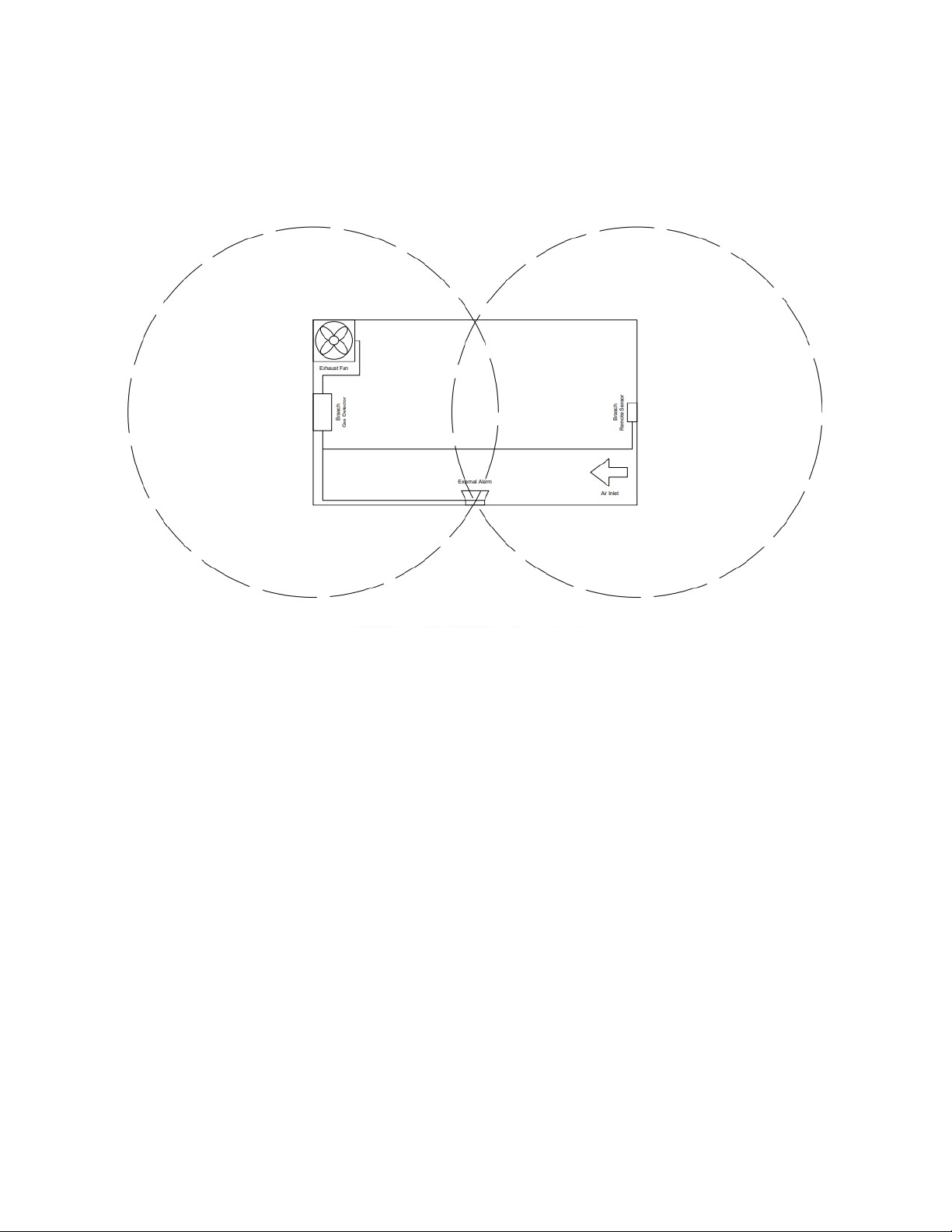
T pical Installation Diagrams
IOM01
Rev 1.0 – December 22, 2020 20
Figure 1: Wiring – Typical Layout
Other manuals for GSE Generation 2
1
Table of contents
Other Brasch Gas Detector manuals

Popular Gas Detector manuals by other brands


Seitron
Seitron RGY 000 MBP4 Operation, installation, and maintenance manual

Emerson
Emerson Rosemount 925FGD manual

Opera
Opera 6000 series Installation guidelines

Siemens
Siemens QRB1 Series manual

Crowcon
Crowcon IRmax Installation, Operating and Maintenance Instruction

Sun Nuclear
Sun Nuclear 1029 user guide