SENKO SI-H100 User manual

ⓒCopyright SENKO CO., LTD.
Page 1/ 31
Sampling type Gas Detector
(SI-H100)
Operating Manual

ⓒCopyright SENKO CO., LTD.
Page 2/ 31
Table of contents
1. Description.......................................................................................................................................................4
2. Product composition..................................................................................................................................5
3. Overview ...........................................................................................................................................................6
4. Specifications .................................................................................................................................................7
5. Composition and name of each part................................................................................................8
1) Front ............................................................................................................................................................8
2) Side...............................................................................................................................................................9
3) Rear..............................................................................................................................................................9
4) Bottom..................................................................................................................................................... 10
5) Exploded view of the products ................................................................................................. 10
6. Cable connection (Power board)...................................................................................................... 11
7. Outside view (Dimensions).................................................................................................................. 12
8. Key information......................................................................................................................................... 13
1) Key Description .................................................................................................................................. 13
2) Key State ................................................................................................................................................ 13
9. Power On....................................................................................................................................................... 14
10. Operation Menu..................................................................................................................................... 15
1) Normal Measurement Menu....................................................................................................... 16
2) Setup/Calibration/Review List Basic.............................................................................................. 16
3) Setup/Calibration Menu Change Basic........................................................................................ 16
4) SET 1......................................................................................................................................................... 17
5) SET 2......................................................................................................................................................... 19
6) SET 3......................................................................................................................................................... 20
7) Calibration............................................................................................................................................. 22
8) Review ..................................................................................................................................................... 24

ⓒCopyright SENKO CO., LTD.
Page 3/ 31
11. MODBUS RS485 Address Map ....................................................................................................... 25
11.1 Interface setting................................................................................................................................. 25
11.2 MODBUS RS485 Register.............................................................................................................. 25
12. MODBUS TCP Address Map ............................................................................................................ 26
12.1 Interface setting................................................................................................................................. 26
12.2 MODBUS TCP Register ................................................................................................................... 26
⚫3000X Register Read.......................................................................................................................... 26
⚫4000X Register Read.......................................................................................................................... 26
⚫4000X Register Write......................................................................................................................... 28
13. Length of installed cable................................................................................................................... 28
14. Error Code.................................................................................................................................................. 30
15. Warranty..................................................................................................................................................... 31
16. Amendment history ............................................................................................................................. 31

ⓒCopyright SENKO CO., LTD.
Page 4/ 31
1. Description
Sampling type Gas Detector (SI-H100) measures sample gas by sensor cartridge in the case upon
suction remotely on a real time basis. It is a device that assists to prevent or control a variety of gas
related accidents including suffocation, intoxication, fire, explosion, corrosion, and so on in multiple
semiconductor or industrial sites.
SI-H100 measures the gas concentration on a real time basis constantly and shows alarm of
dangerous concentration, fault situation, and so on, upon attaching on the wall.
By operating four buttons in the lower part of the screen, environmental setting of the device can
be easily amended.
Measured gas concentration is transmitted with 4-20mA output on a real time basis and external
operations according to the desired situations can be variously organized by three internal relays.
In addition, it is possible to output MODBUS/TCP, and to solve data transmission and power at the
same time only with a LAN cable (PoE).
WARNING
Please be aware of the manual before using the device. This device
should be used and maintained according to the instruction and it may
cause the damage of the device, or the user’s injury or fatality in case not
to conform the instruction.
ⓒCopyright SENKO CO., LTD.
Page 5/ 31
2. Product composition
SI-H100 consists of four parts including case, sensor cartridge, main frame, and prob for installation.
Also, it contains the accessary of thermal decomposition module(Pyrolyzer) to be used upon
additional purchasing to be able to detect and measure the gas by thermal decomposition in case
of the materials without gas sensor such as NF3.
ⓒCopyright SENKO CO., LTD.
Page 6/ 31
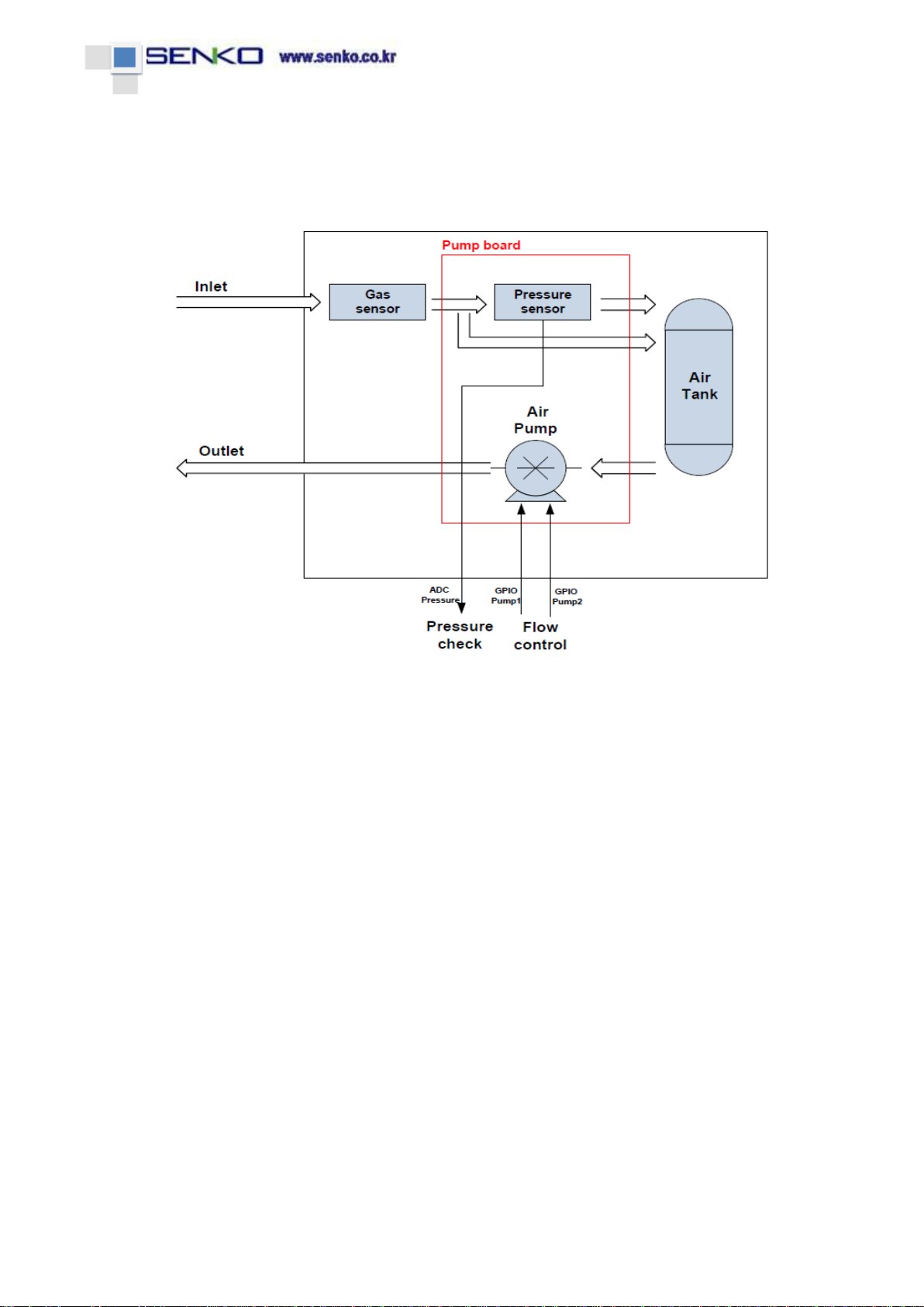
3. Overview
Figure 1 Overview

ⓒCopyright SENKO CO., LTD.
Page 7/ 31
4. Specifications
Item
Specification
Size
124mm(H) X 65mm(W) X 155mm(D)
Weight
2Kg
Operating voltage
DC : 24V ± 10%
PoE : 36V~57V (Typical : 48V)
Flow rate
500mL/min (MAX 900)
Power consumption
Approximately 5.0W
Measurement display
Graphic LCD (160 X 100), gas concentration, flow
rate, alarm, rear light, alarm, device abnormality
Relay
Primary Alarm, Secondary Alarm, Fault Alarm
Output signal
Analog, 4-20mA
Digital communication
RS-485, TCP Ethernet
Sampling distance
Length of input gas tube: up to 30m (FEP tube)
Length of exhaust gas tube: up to 30m (FEP tube)
input/output tube
1/4” Teflon tube
Operating temperature
0°C ~40°C
Certification
CE
Control/Set
4 Button & RS485 & Ethernet
Warranty period of the
device
2 years
Warranty period of
sensor cartridge
1 year
Remote interface
Ethernet, RS-485
Wiring
4 to 20mA / DC power / Relay: up to 14 AWG
ⓒCopyright SENKO CO., LTD.
Page 8/ 31
5. Composition and name of each part
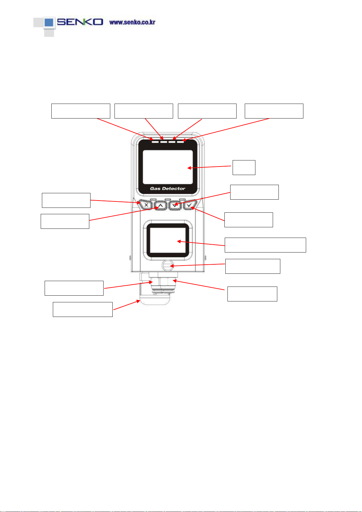
1) Front
Power LED(Green)
Alarm1 LED(Red)
Alarm2 LED(Red)
Fault LED(Red)
LCD
Menu button
Down button
UP button
Select button
Sensor cartridge window
Thumb screw
Gas inlet port
Gas outlet port
Cable Gland
ⓒCopyright SENKO CO., LTD.
Page 9/ 31
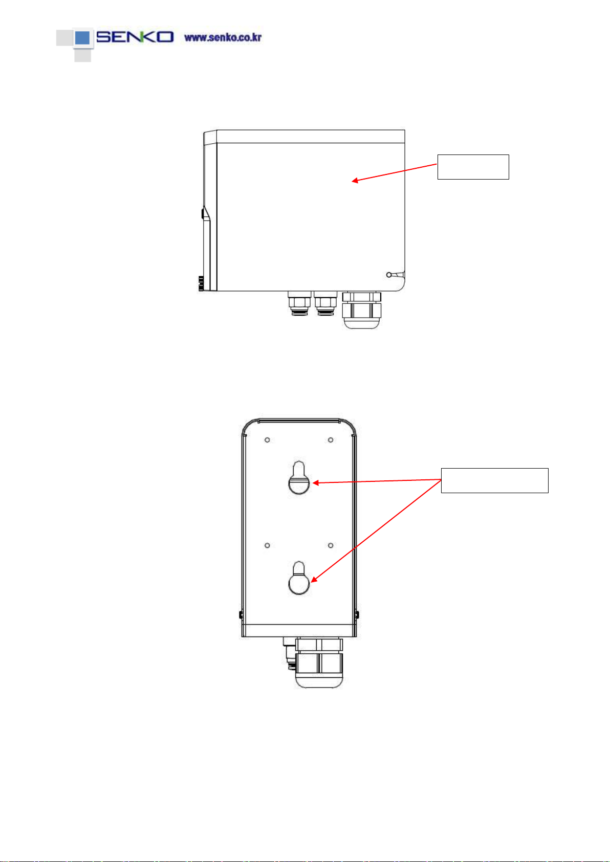
2) Side
3) Rear
Unit cover
Mount bracket hole
cover

ⓒCopyright SENKO CO., LTD.
Page 10 / 31
4) Bottom
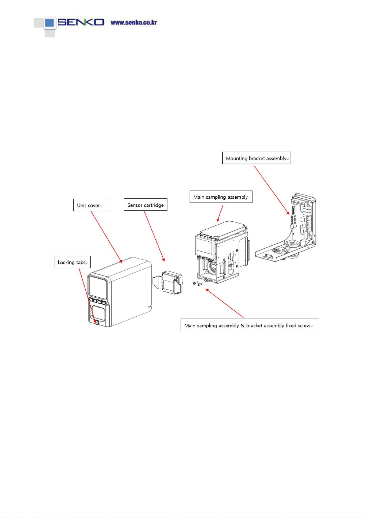
5) Exploded view of the products
Ethernet/PoE socket
Unit cover
Sensor cartridge
Mounting bracket assembly
Main sampling assembly
Main sampling assembly & bracket assembly fixed screw
Cable Gland
Gas inlet port
Gas outlet port
Locking tabs

ⓒCopyright SENKO CO., LTD.
Page 11 / 31
6. Cable connection (Power board)
Power ON/OFF switch
Ethernet/PoE socket
In case of power supply
with PoE, PoE switch
hub should be used.
Power cable : DC 24V
Power cable : Ground
ALARM LOW(1st) Relay
ALARM HIGH(2nd) Relay
Fault Relay
RS-485 : A
RS-485 : B
4to20mA out : Signal
4to20mA out : Ground
High(2nd) Alarm Jumper : 1-2 :NC /2-3:NO
Low(1st) Alarm Jumper : 1-2 :NC /2-3:NO
Fault Jumper : 1-2 :NC /2-3:NO

ⓒCopyright SENKO CO., LTD.
Page 12 / 31
7. Outside view (Dimensions)

ⓒCopyright SENKO CO., LTD.
Page 13 / 31
8. Key information
1) Key Description
Key
Name
Description
Menu
Menu/Cancel & Return to Previous Step
Up
Movement of List Focus and Value Change
Up Long
Movement of Focus in Screen Setting
Down
Movement of List Focus and Value Change
Down Long
Movement of Focus in Screen Setting
Select
Select and Save
2) Key State
State
Pressed Time
Description
Normal Key
100ms below
Menu and Set value Changes
Long Key
1000ms over
Movement of Focus
Forward/Backward in Each Setting

ⓒCopyright SENKO CO., LTD.
Page 14 / 31
9. Power On
1) Connect the wire after checking power voltage
2) Transit into Measure state after turning on Power LED (Green) and Version information
display
3) It takes about 15 seconds.
Booting and Warm up
Measurement

ⓒCopyright SENKO CO., LTD.
Page 15 / 31
10. Operation Menu
- Pushing Menu key, change the circulation with Normal →SET 1 →SET 2 →SET 3 →CAL
- Enter Review with Select key in Normal, return to Normal with Menu key.
[Power On]
[Normal Measure]
[SET 1]
[SET 2]
[SET 3]
[Calibration]
[Review]
ⓒCopyright SENKO CO., LTD.
Page 16 / 31
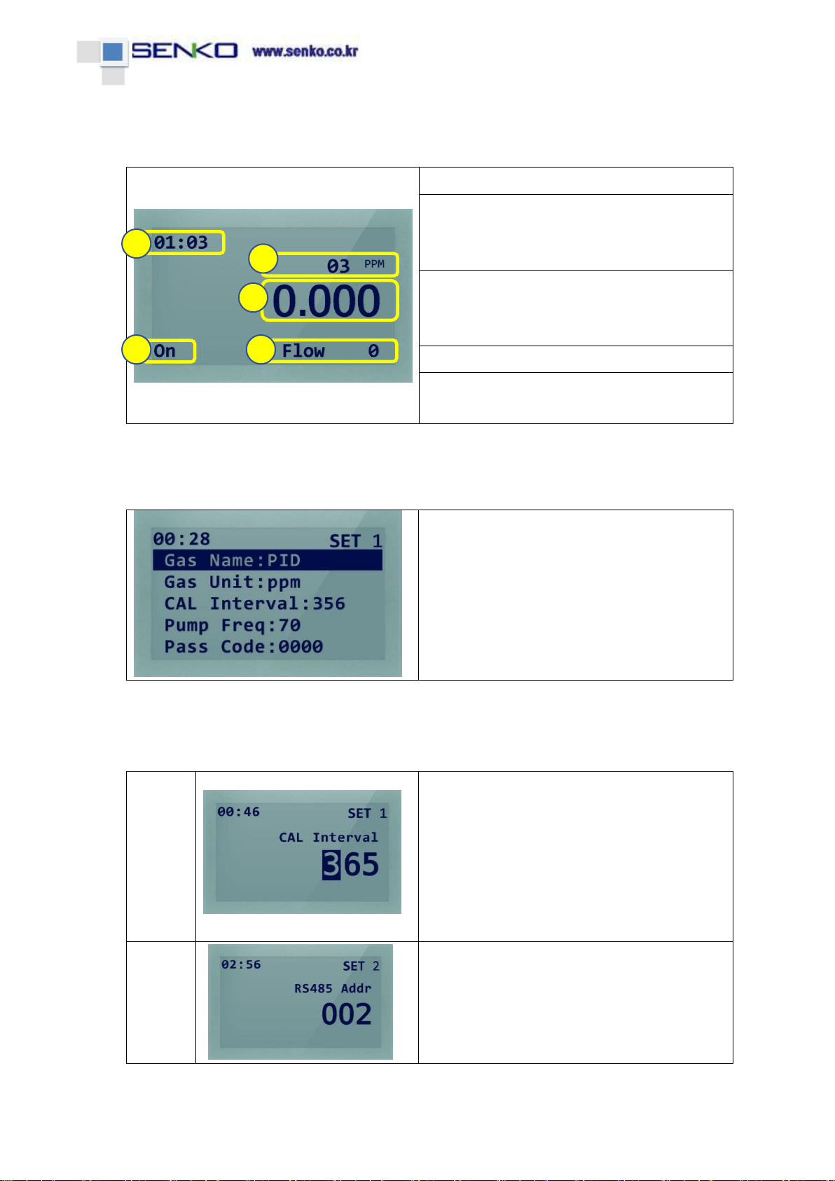
1) Normal Measurement Menu
Current time: display 24-hour system
Current sensor gas type / concentration unit
- O3: gas type in the installed sensor
- ppm: concentration unit
Concentration of measured gas
- Decimal position is changed according to the
measurement range of the sensor.
Sensor On/Off State
Pump flow rate
- Current suction flow rate
2) Setup/Calibration/Review List Basic
1. Current Menu display upper right
- SET1, SET2, SET3, CAL, REVIEW
2. Move List Focus by Up/Down Key
3. Pushing Select key, enter the setting screen
- In case the related setting is not possible, no
screen change
4. Pushing Menu key, move the next Menu
3) Setup/Calibration Menu Change Basic
Menu
with
Focus
1. Change number 0-9 with Up/Down key
2. Move Focus by Up/Down long Key
- Pushing Down Long key, Focus movement
in the order of 3 →6 →5 →3
3. If Focus is moved with the number over
setting range, it is changed into Max value or
effective value, automatically.
Menu
without
Focus
1. Change the number with Up/Down key
2. Input Up/Down Long key increases or
decreases the number continuously.
1
4
5
2
3

ⓒCopyright SENKO CO., LTD.
Page 17 / 31
4) SET 1
1) Gas Unit: Gas concentration unit
2) CAL Interval: Set calibration interval
3) Pump Freq: Control suction amount by setting Frequency of Gas Suction Pump
4) Pass Code: Set Setup and Calibration entry passcodes
5) Inhibit: Set items to inhibit
6) Buzzer: Buzzer On/Off in case of Alarm occurrences
7) Resp Factor: Value of fine control for Gas concentration
8) Sensor Off: Control the time from On to Off of Sensor automatically (for VOC sensor)
9) RS485 Addr: Set device address during RS485 communication
1) Gas Unit
▶Adjust concentration unit with Up/Down key
▶Cancel with Menu key, Save with Select key
▶Possible to set ppm/ppb/Vol/LEL
▶Default: ppm
2) CAL Interval
▶Change number 0-9 with Up/Down key
▶Move Focus with Up/Down Long key
-Up Long: Move Focus left
-Down Long: Move Focus right
▶Cancel with Menu key, Save with Select key
▶Possible to set up to 0 ~ 999 days
▶Default: 365 days
3) Pump Frequency
▶Adjust number with Up/Down key
▶Adjust number continuously with Up/Down Long key
▶Cancel with Menu key, Save with Select key
▶Flow : Display current flow rate
▶Default : 60 Hz
4) Pass Code
▶Adjust number (0-9) with Up/Down key
▶Move Focus with Up/Down Long key
-Up Long : Move Focus left
-Down Long : Move Focus right
▶Cancel with Menu key, Save with Select key
▶Set only in case of input the same Pass Code twice
▶In case of setting Pass Code with the value other than
0000, entry is possible only with input Pass Code upon
entry to setting by Menu key.
▶Default : 0000

ⓒCopyright SENKO CO., LTD.
Page 18 / 31
5) Inhibit
▶Set Inhibit item with Up/Down key
▶Cancel with Menu key, Save with Select key
▶None: No Inhibit
Alm: Alarm Inhibit
Alm&Flt: Alarm, Fault Inhibit
Full: Inhibit all items
▶Default: None
6) Buzzer
▶Set Buzzer On/Off with Up/Down key
▶Cancel with Menu key, Save with Select key
▶On: In case of Alarm, Buzzer sound
Off: In case of Alarm, no Buzzer sound
▶Default : On
7) Resp Factor
▶Adjust number (0-9) with Up/Down key
▶Move Focus with Up/Down Long key
-Up Long: Move Focus left
-Down Long: Move Focus right
▶Cancel with Menu key, Save with Select key
▶It will be output by multiplying the final concentration.
▶Default : 1.00
8) Sensor Off Time
▶Adjust number with Up/Down key
▶Adjust number continuously with Up/Down Long key
▶Cancel with Menu key, Save with Select key
▶Automatic Off time: Off(Always On), 1~120 seconds
-Menu only for VOC sensor (PID)
-Sensor Power Off if the related time is passed
▶Default : Off
9) RS485 Addr
▶Adjust number with Up/Down key
▶Adjust number continuously with Up/Down Long key
▶Cancel with Menu key, Save with Select key
▶RS485 Address(ID) : 1 ~ 247
▶Default : 1
ⓒCopyright SENKO CO., LTD.
Page 19 / 31
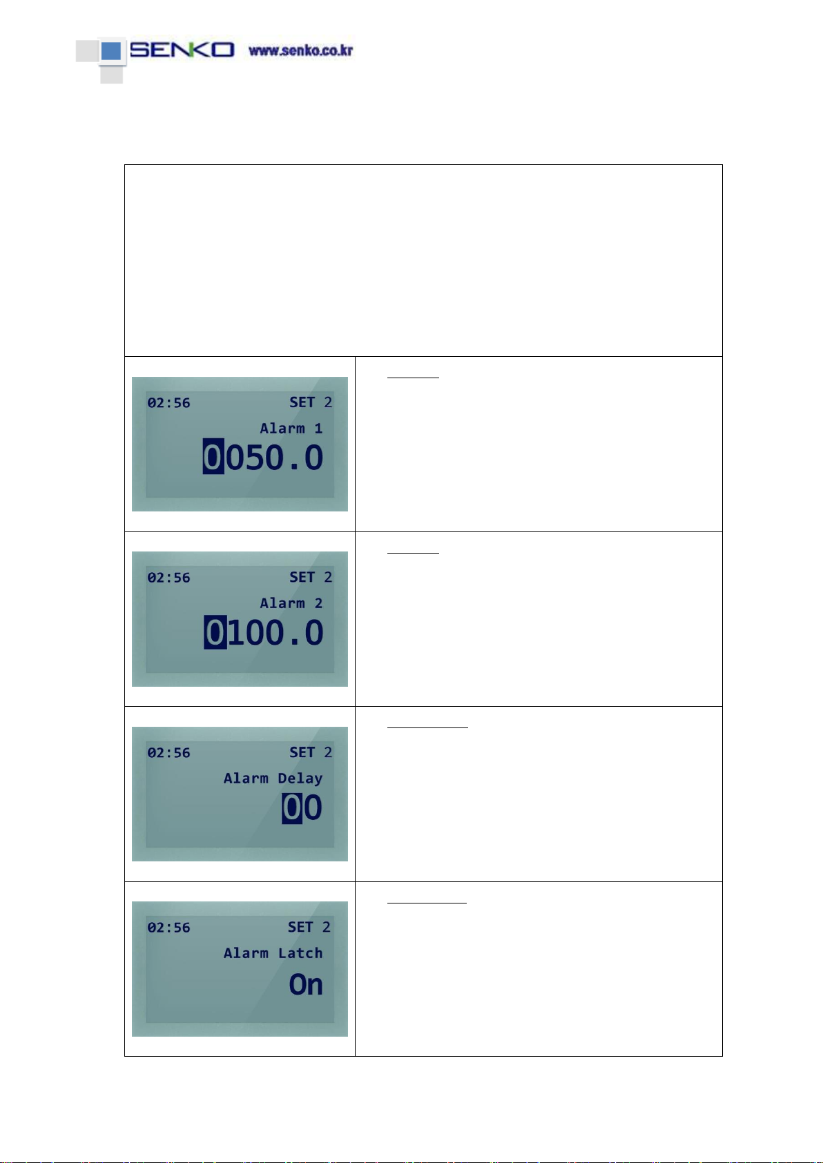
5) SET 2
1) Alarm 1: Set Alarm Level 1(Low)
2) Alarm 2: Set Alarm Level 2(High)
3) Alarm Delay: Alarm is occurred after the setting time in case achieving the concentration
of Alarm 1, 2
4) Alarm Latch: Set whether to clear Automatic or Manual after Alarm occurrence
5) Alarm Relay: Set whether to operate Relay simultaneously in case of Alarm occurrence
6) Fault Latch: Set whether to clear Automatic or Manual after Fault occurrence
7) Fault Relay: Set whether to operate Relay simultaneously in case of Fault occurrence
1) Alarm 1
▶Adjust number (0-9) with Up/Down key
▶Move Focus with Up/Down Long key
-Up Long : Move Focus left
-Down Long : Move Focus right
▶Cancel with Menu key, Save with Select key
▶Alarm Level 1 : 0 ~ 9999.9 ppm
▶Default : 50.0 ppm
2) Alarm 2
▶Adjust number (0-9) with Up/Down key
▶Move Focus with Up/Down Long key
-Up Long : Move Focus left
-Down Long : Move Focus right
▶Cancel with Menu key, Save with Select key
▶Alarm Level 2 : 0 ~ 9999.9 ppm
▶Default : 100.0 ppm
3) Alarm Delay
▶Adjust number (0-9) with Up/Down key
▶Move Focus with Up/Down Long key
-Up Long : Move Focus left
-Down Long : Move Focus right
▶Cancel with Menu key, Save with Select key
▶Alarm Delay : 0 ~ 99 seconds
▶Default : 0 second
4) Alarm Latch
▶Set Alarm Latch with Up/Down key
▶Cancel with Menu key, Save with Select key
▶On: Alarm is not cleared even if Alarm condition is
cleared after Alarm occurrence
Off: Alarm is automatically cleared if Alarm condition
is cleared after Alarm occurrence
▶Default : Off
ⓒCopyright SENKO CO., LTD.
Page 20 / 31
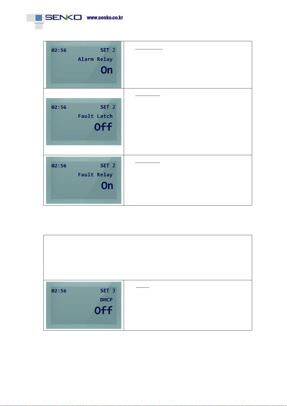
5) Alarm Relay
▶Set Alarm Relay with Up/Down key
▶Cancel with Menu key, Save with Select key
▶On: Operate Relay in case of Alarm occurrence
Off: Do not operate Relay in case of Alarm occurrence
▶Default : On
6) Fault Latch
▶Set Fault Latch with Up/Down key
▶Cancel with Menu key, Save with Select key
▶On: Fault is not cleared even if Fault condition is
cleared after Fault occurrence
Off: Fault is automatically cleared if Fault condition is
cleared after Fault occurrence
▶Default : Off
7) Fault Relay
▶Set Fault Relay with Up/Down key
▶Cancel with Menu key, Save with Select key
▶On: Operate Relay in case of Fault occurrence
Off : Do not operate Relay in case of Fault occurrence
▶Default : On
6) SET 3
1) DHCP: Set Network DHCP On/Off
2) IP Address: Set Network IP Address
3) Subnet Mask: Set Network Subnet Mask
4) Gateway: Set Network Gateway
5) Time: Set time and date
6) Backlight: Set Backlight in case of Alarm/Fault
1) DHCP
▶Set DHCP with Up/Down key
▶Cancel with Menu key, Save with Select key
▶On: Automatically allocate Network IP Address
Off: Manually allocate Network IP Address
▶Default : Off
Other manuals for SI-H100
1
Table of contents
Other SENKO Gas Detector manuals

SENKO
SENKO SP secure User manual

SENKO
SENKO SI-560D User manual

SENKO
SENKO SP-MGTP User manual

SENKO
SENKO SGT-P User manual

SENKO
SENKO iGas Detector CO2 User manual

SENKO
SENKO RAITEC SI-100D User manual

SENKO
SENKO SP-MGTP User manual

SENKO
SENKO SI-300 User manual

SENKO
SENKO SGT User manual

SENKO
SENKO MGT User manual


Popular Gas Detector manuals by other brands


Medem
Medem AGDS-2em installation instructions

ABB
ABB 2CSE1220EL manual

Pilot Communications
Pilot Communications 2011319/716/12 Operation and maintenance manual

MSA
MSA ALTAIR4 Quick start card

S&S Northern
S&S Northern MERLIN GDP2-X Installation & operation manual

New Cosmos Electric
New Cosmos Electric ML-310 user manual