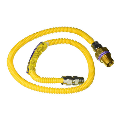
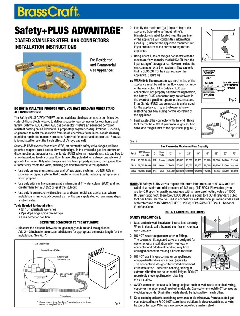
BrassCraft ProCoat CSSL User manual

THE SAFE, EASY WAY TO INSTALL HOME GAS APPLIANCES.
Coated stainless steel gas appliance connectors provide a
safe and easy method to install gas ranges, water heaters,
ovens, furnaces and gas dryers. The corrugated tube
allows the exibility you need to align the appliance to the
rigid gas supply pipe. The proprietary coating provides
excellent available corrosion protection from most harsh
household cleaning and plumbing repair chemicals.
❏Approved for use with natural, manufactured, L.P.
(propane), and L.P. air mixture gases with internal
line pressure no greater than 1/2 lb. per square
inch (psi).
❏Design certied by CSA, and listed by the New York
City Board of Standards and Appeals and the
Commonwealth of Massachusetts.
❏Designed, Machines and Assembled in the USA and
100% leak tested.
CAUTION: DO NOT INSTALL THIS PRODUCT UNTIL YOU READ AND UNDERSTAND
ALL INSTRUCTIONS. FAILURE TO FOLLOW THESE INSTRUCTIONS MAY RESULT IN
PERSONAL INJURY, PROPERTY DAMAGE OR PRODUCT FAILURE.
Even an outstanding system can become a hazard due to poor installation, inspection
or testing. Please read all precautions and installation instructions before beginning
connector installation.
SAFETY PRECAUTIONS:
❏ WARNING: Gases can be ignited by a ame or spark, which may result in an
explosion. Please follow installation instructions carefully. When in doubt, call a
licensed plumber or your local gas company.
❏ WARNING: DO NOT re-use connectors, ttings and valves; they are designed for
use on original installation only. Removal of connector and additional handling may
damage connector making it unsafe for reuse.
❏ WARNING: DO NOT use this connector if it has been in a re. Fire can damage
the connector making it unsafe for use.
❏ WARNING: DO NOT use this connector on
appliances equipped with rollers or casters.
This connector is designed for limited movement
after installation. Repeated bending, exing or
extreme vibration can cause metal fatigue. Normal
vibration and movement of standard household gas
dryer or similar appliance is okay.
❏ WARNING:
DO NOT use connectors to make a
direct connection to LP gas containers. Connection
MUST be made to the regulator device only.
❏ WARNING: DO NOT use connector on appliances
in moving vehicles such as RV’s, trailers, etc.
However, this product may be used in manufactured
housing (permanent residence mobile homes).
ProCoat®
COATED STAINLESS STEEL GAS CONNECTORS
SELECTION & INSTALLATION INSTRUCTIONS
For Residential and Commercial Gas Appliances
❏ WARNING: DO NOT use this connector with
infrared radiant tube heaters. Cyclic movement of
heater may cause connector to fail.
❏ WARNING: Keep cleaning solvents containing
ammonia or chlorine away from an uncoated
or damaged gas connector. DO NOT store these
solutions near connector or use the connector near a
swimming pool or hot tub. Water rinse the connector
thoroughly if exposed to these chemical products.
❏ WARNING: DO NOT join this connector to another connector.
❏WARNING: DO NOT stretch connector to make it t. Connector must be at least
2 to 3 inches longer than the distance from the gas supply line to appliance when
pulled out from the supply at its maximum length.
WARNING: Connector is for use in accessible locations only. DO NOT conceal
connector or run connector through enclosed outdoor BBQ pits, walls, partitions,
oors or appliance panels.
❏ WARNING: DO NOT connect gas connector nuts directly to pipe threads of gas
supply pipe or appliance. Install connector using the ttings provided. (see Figure A)
CODES AND REGULATIONS
Gas appliance and connector installation MUST conform with all local codes and
regulations including municipal and state building codes, and to all local utility
regulations. In the absence of local code, the installation must conform with the
National Fuel Gas Code ANSI Z223.1/ NFPA No. 54, Uniform Plumbing Code, or
International Fuel Gas Code. Contact your local gas company for details.
INSTALLATION INSTRUCTIONS:
WARNING: Turn off gas supply before disconnecting old appliance. In absence of
manual shut-off valve near appliance location, gas MUST be shut off at main valve,
near meter.
NOTE: Fuel gas codes require installation of a manual shut-off valve in the same
room, within easy reach of the appliance (i.e. within 6 feet).
1. Clean all pipe threads with a wire brush and rag to ensure connections are free
of any debris such as metal shavings, rust, dirt, oil or water.
2. Apply pipe thread sealant to the male pipe threads
of connection. DO NOT apply sealant or tape to are
ends of ttings or shut-off valve. Sealant and tape
will prevent this connection from sealing properly.
3. If necessary, thread new manual shut-off valve onto
gas supply pipe, wrench tighten.
4. Thread steel tting to manual shut-off valve and
other steel tting onto appliance regulator.
5. Thread are nuts of gas connector onto shut-off valve and steel tting. Wrench
tighten all connections.
TO METER
Figure A
TO APPLIANCE

WARNING: DO NOT stretch the connector to
make it t. Connector must be long enough to
allow the appliance to be positioned at its farthest
anticipated connected distance from the gas supply
without stretching, twisting or bending smaller that a
1-1/2 internal diameter (diameter of a golf ball).
WARNING: DO NOT trap connector against sharp
edges or corners.
CAUTION: DO NOT kink, twist or bend connector sharply.
6. Turn manual shut-off valve on to allow gas to enter system.
WARNING: DO NOT TURN ON APPLIANCE until all
connections have been leak tested!
WARNING: DO NOT USE matches, candles, open
ames or other sources of ignition to leak test
connections!
7. Test all connections with leak test solution provided,
or with clear soap and water solution; bubbles will
indicate a leak. If a leak is detected, turn off gas
supply before further tightening connections. Water
rinse and towel dry connector once test is complete.
8. Wait at least 10 minutes to be certain that all vapors
have dissipated. If leak test conrms connections do
not leak gas, and you do not smell any gas,
THEN light pilot(s) and turn on appliance.
Tools Needed for Installation:
• (2) 10 in. adjustable wrenches
• Pipe dope or gas pipe thread tape
• Leak detection solution
X
©2009, 2019 Brasscraft Manufacturing Company 325.01 Rev. 11/19
Brasscraft Manufacturing Co., 39600 Orchard Hill Place Novi, Michigan 48375-5331
TOLL-FREE: 877.272.7755 FAX: 248.305.6011 www.brasscraft.com
Manufacturer assumes no responsibility for failure due to improper installation.
©2019 Brasscraft Manufacturing Company, Novi, MI 48375-5331 U.S.A.
All Rights Reserved. www.brasscraft.com BrassCraft®brand is a trademark of Brasscraft Mfg. Co.
El fabricante no asume ninguna responsabilidad si la instalación no se hace de acuerdo al instructivo.
BrassCraft®brand es una marca registrada de Brasscraft Mfg. Co.
Gas Connector Maximum Flow Capacity
Part # ID
Color Code 12 in 18 in 24 in 30 in 36 in 48 in 60 in 72 in
Gas Connector with Standard Fittings
CSSL
1/4 BTU’s 48,000 43,800 40,000 36,400 33,400 28,300 24,900 23,100
Purple Watts 14,067 12,837 11,723 10,668 9,789 8,294 7,297 6,770
CSSD
3/8 BTU’s 102,000 93,100 85,000 77,100 71,100 60,500 53,200 49,100
Green Watts 29,893 27,285 24,911 22,596 20,837 17,731 15,591 14,390
CSSC
1/2 BTU’s 180,000 164,200 150,000 136,000 125,000 106,000 93,200 86,000
Gold Watts 52,752 48,122 43,961 39,858 36,634 31,066 27,314 25,204
Safety+Plus® (Gas Connector with Excess Flow Valve Attached)
CSSL
1/4 BTU’s 42,000* 37,400* 36,800* 36,400 33,400 28,300 24,900 23,100
Purple Watts 12,308* 10,960* 10,784* 10,668 9,789 8,294 7,297 6,770
CSSD
3/8 BTU’s 102,000 93,100 85,000 77,100 71,100 60,500 53,200 49,100
Green Watts 29,893 27,285 24,911 22,596 20,837 17,731 15,591 14,390
CSSC
1/2 BTU’s 122,000* 118,000* 115,000* 111,000* 107,000* 106,000 93,200 86,000
Gold Watts 35,754* 34,581* 33,702* 32,530* 31,358* 31,066 27,314 25,204
*
Note: Connecting the safety valve lowers these values below the Z21.24/CSA 6.10 and Z21.75/CSA 6.27 standards
Listings & Certications:
Components CSA listed to ANSI Z21.24 / CSA 6.10 standard “Connectors for
Gas Appliances”
Components CSA listed to ANSI Z21.75 / CSA 6.27 standard “Connectors for
Outdoor Gas Appliances & Manufactured Homes”
NOTE: This connector meets or exceeds the minimum allowable capacity
as determined under test conditions specified in ANSI Z21.24 • CSA 6.10.
Straight length capacity rated in BTU per hr. using: 0.64 SP. Gr., 1000 BTU per
Cu Ft. Gas at 0.50 inch Water Column Pressure Drop. The capacity at 50 Pa
(0.2 inch water column) pressure drop can be determined by multiplying the
BTU per hr. listed in the table above by 0.632
.
This manual suits for next models
2
Other BrassCraft Cables And Connectors manuals
