Page 8
Tower 3 (Alarm) Switch Adjustment
Threshold Alarm Switch
1. Position platform at the fully raised
(floor level) position using the pen-
dant control.
2. Place pressure on the threshold
warning plate (base plate). Con-
tinue applying pressure to threshold
plate and turn switch adjustment
screw clockwise until alarm sounds.
If alarm sounds when pressure is
first applied go to Step 3.
3. Continue applying pressure to
threshold plate and slowly turn
switch adjustment screw coun-
terclockwise until the alarm stops
sounding.
Tower 4 (Fold) Switch Adjustment
Partial Fold
1. Position platform at 45˚angle using
the manual hand pump or pendant
control.
2. View the Tower 4 microswitch inside
the lift tower (see Photo B). Turn
the switch adjustment screw in or
out as needed until the radius of the
microswitch blade rides on the apex
of the activation plate.
3. Verify proper adjustment. Criteria
below must be met.
Proper Adjustment Criteria:
• Apply pressure (push down) on
outboard end of platform by press-
ing the hand pendant FOLD switch.
The platform should not fold (stow)
with light pressure applied.
• When folding fully, the platform
should stow tightly (snug with stow
blocks).
Figure E Note: Left (rear) pump lift de-
picted. Right (front) pump
lift is a mirrored image.
Note: Review adjustment
procedures below and adjust
as needed only.
Tower 1 (Unfold) Switch Adjustment
Floor Position from Stow
1. Position platform at the fully stowed
position using the manual hand
pump or pendant control.
2. Turn switch adjustment screw clock-
wise 3 full turns.
3. Press pendant UNFOLD switch (con-
tinue pressing switch until platform
stops unfolding).
4. When platform stops unfolding, turn
switch adjustment screw coun-
terclockwise while pressing the
pendant UNFOLD switch. Platform
position will change. Repeat adjust-
ment until criteria below is met.
Proper Adjustment Criteria:
• Bridge plate should just rest on
threshold plate (base plate).
• Should be an approximate 1/8˝
clearance between outboard end of
rotating pivot slide arm saddle and
the lower parallel arm. See Photo
A.
Tower 2 (Up) Switch Adjustment
Floor Position from Below Floor
1. Lower platform a minimum of 6˝
below floor level position using the
manual hand pump or pendant
control.
2. Turn switch adjustment screw coun-
terclockwise 3 full turns.
3. Press pendant UP switch (continue
pressing switch until platform stops).
4. When platform stops, turn switch
adjustment screw clockwise while
pressing the pendant UP switch.
Platform position will change. Ad-
just platform to meet criteria listed
for Tower 1 Proper Adjustment
Criteria.
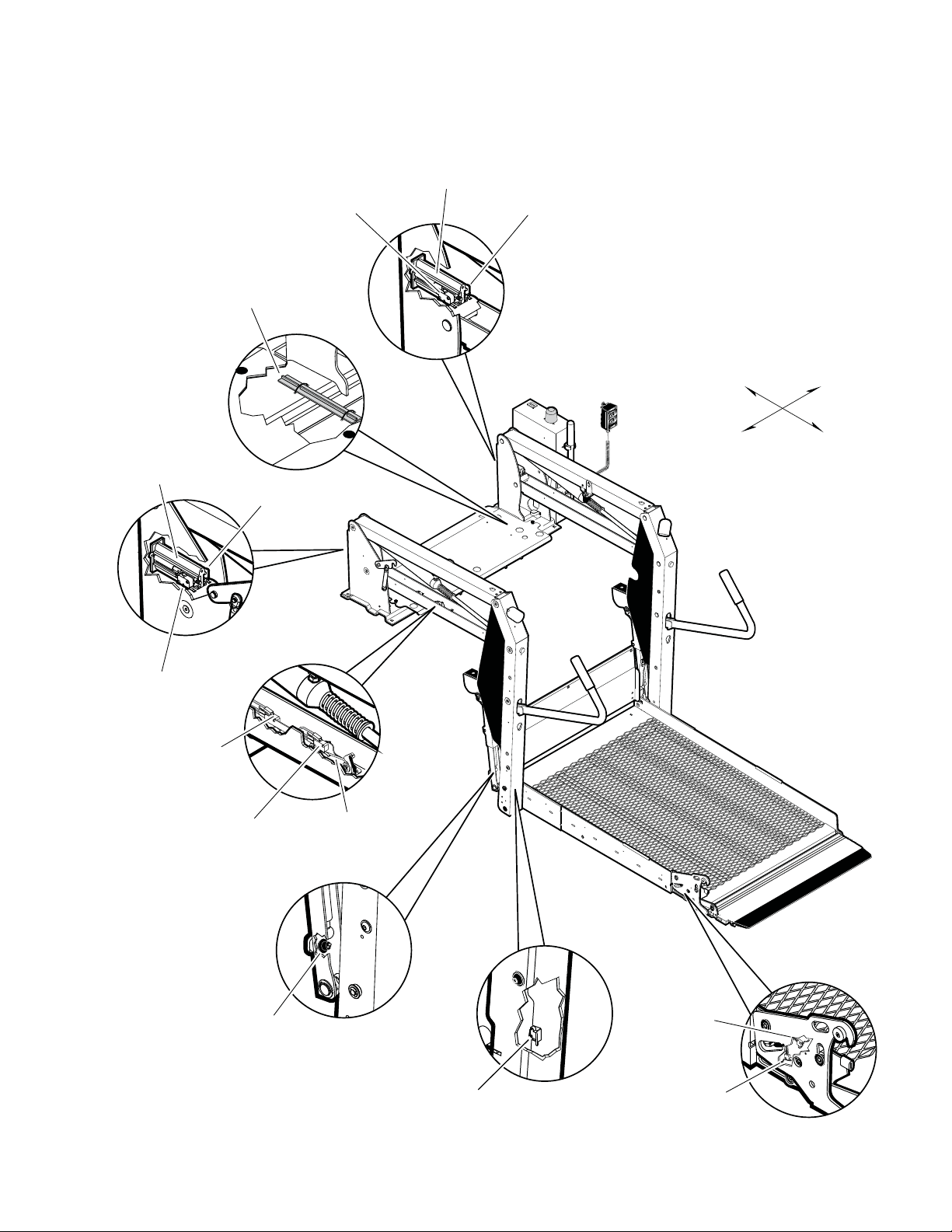
TOWER
2
TOWER
1
32942
TOWER
4
TOWER
3
32943
A
B
Radius of Tower 4 Micro-
switch Blade activated by
Apex of Activation Plate.
1/8"
TOWER
2
TOWER
1
32942
TOWER
4
TOWER
3
32943
Tower Microswitch Adjustment