Atlas Rave 2 User manual
RAVE 2
STAIR LIFT
Installation Manual

Table of Contents
SAFETY ...................................................................................
Safety Denition .....................................................................
Environmental Cautions ........................................................
INTRODUCTION .....................................................................
Device Name: Rave II Series .................................................
Read and Understand ............................................................
Warranty ..................................................................................
Technical Specications .......................................................
Code Statement .....................................................................
PREPARATION .......................................................................
Required Tools ........................................................................
Included Parts .........................................................................
Rail Box Content .....................................................................
Rail Bracket Box ......................................................................
Chair and Footrest Box ..........................................................
INSTALLATION ......................................................................
Determine Overall Rail Length ..............................................
Installation Site Electrical Requirements .............................
Rail Installation .......................................................................
Zero Intrusion Installation .....................................................
Chassis Installation ................................................................
Final Rail Installation ..............................................................
Footrest and Seat Installation ...............................................
Procedure to Switch Armrest Control
From Right to Left Hand ........................................................
Folding Rail Installation ......................................................... 046_Atlas_Rave2_InstallManual_0821
4
4
4
5
5
5
5
5
5
6
6
6
6
6
6
7
7
8
8
10
11
12
13
15
16
COMPLETION PROCEDURES ..............................................
Remote Control Re-Programming ........................................
Test Armrest Control .............................................................
Tighten Brackets ....................................................................
Set Upper and Lower Travel Limits ......................................
Test Safety Stop Switches ....................................................
Additional System Check ......................................................
TROUBLESHOOTING ............................................................
Major Faults ............................................................................
Minor Faults ............................................................................
Pulsing Beep ...........................................................................
Manual Override Operation ...................................................
19
19
19
20
20
20
21
22
22
22
22
22

This safety alert symbol appears with
safety statements. It means attention,
become alert, your safety and the
safety of others are involved! Please
read and abide by the message that
follows the safety alert symbol.
SAFETY DEFINITIONS
safety
2
NOTE: Indicates a condition that should be followed in order for
the lift to function in the manner intended.
The technician shall assess the surrounding conditions
and verify that the location is acceptable before
performing installation and/or servicing tasks. If you do
not understand any portion of the installation or operation
procedures, please consult Atlas' Technical Service
Department at 866-378-6648. Do not attempt to install
or use this lift if you have any hesitation or question.
Serious injury or damage can result if proper procedures
are not followed.
ENVIRONMENTAL CONDITIONs
Indicates a hazardous situation that, if not avoided,
could result in death or serious injury.
Indicates a hazardous situation that, if not avoided,
could result in minor or moderate injury.
Indicates a situation which can cause damage to the
lift and / or the environment, or cause the lift to operate
improperly.
RAVE 2 INSTALLATION MANUAL SAFETY

3
DEVICE NAME: RAVE II SERIES
INTRODUCTION
Visit atlasacces.com for specications on the lift model.
TECHNICAL SPECIFICATIONS
Indications of Use: The Atlas Rave II is to assist the
transfer of patients or mobility impaired persons up and
down levels of a residence.
READ AND UNDERSTAND
This manual provides instructions for proper installation
and maintenance of the Rave II stair lift. Please refer to the
owner’s manual for operating instructions. Any alterations
to the equipment without written authorization by the
manufacturer is prohibited and will void the warranty.
WARRANTY
Please ensure that you advise the owner of the Rave II stair
lift to ll out the separate warranty form and return it within
ten (10) days of purchase to register the lift.
CODE STATEMENT
Code requirements for Rave II may vary depending on
location. It is the installer’s responsibility to contact their
state, city or local code enforcement oce and determine
all the regulations the lift and installation are subject to.
This must be done before installing the Rave II.
Intertek (ETL) Certied to ASME A18.1-2017 section 4
and section 7.
RAVE 2 INSTALLATION MANUAL INTRODUCTION

4
PREPARATION
Before beginning installation, inspect and check the box
contents and report any damage or missing items to Atlas.
INCLUDED parts
Installations may vary to some degree, but below are the basic tools to have on hand for a Rave II stair lift installation.
If you have any questions, concerns or comments, please contact our Technical Service Department at 866-378-6648.
REQUIRED TOOLS
• Cordless drill
• Allen wrenches (5/64",
(5/32", 3/16", 5/16")
• Phillips screwdriver (#3)
• Nut driver (3/8", 5/16")
• 6" - 10" driver extension
RAIL BOX CONTENT
• Chassis
• 2 wireless call/send hand controls
• Manual override tool (optional)
• Level
• Hack saw or chop saw
• SAE socket set
• SAE wrenches
• Tape measure
• Volt meter
• Rail accessories
(plastic bag) with:
− Top end plate
− Compression bolts
(2 sizes)
− Self-cutting screws
1/4"-20 x 1"
− Torx T30 driver bit
− Extra plastic racks
(2 or 3)
− Top limit cam
• Bottom rail pre-installed with:
− Bottom end plate
− Charge strip wire harness
• Bottom limit cam
• Joint pins (two-piece rail only)
• Plastic gear rack
• Top rail pre-installed with
charge strip wire harness
RAIL bracket box
• Rail brackets (2, 3, 4, or 6 per set)
• Wood screws #14 x 2" (4 per rail bracket)
CHAIR AND FOOTREST BOX
• Chair with retractable seatbelt
• Footrest complete with adjustable seat height frame
• Plastic vertical cover
• 5 nylon plugs
• Seat swivel post with fasteners
RAVE 2 INSTALLATION MANUAL PREPARATION
5
DETERMINE OVERALL RAIL LENGTH
INSTALLATION
NOTE: Use this only if the rail did NOT come precut to length)
1. Determine any obstructions that will affect the position
and length of the rail. These may include walls, doors,
hallway orientation, etc.
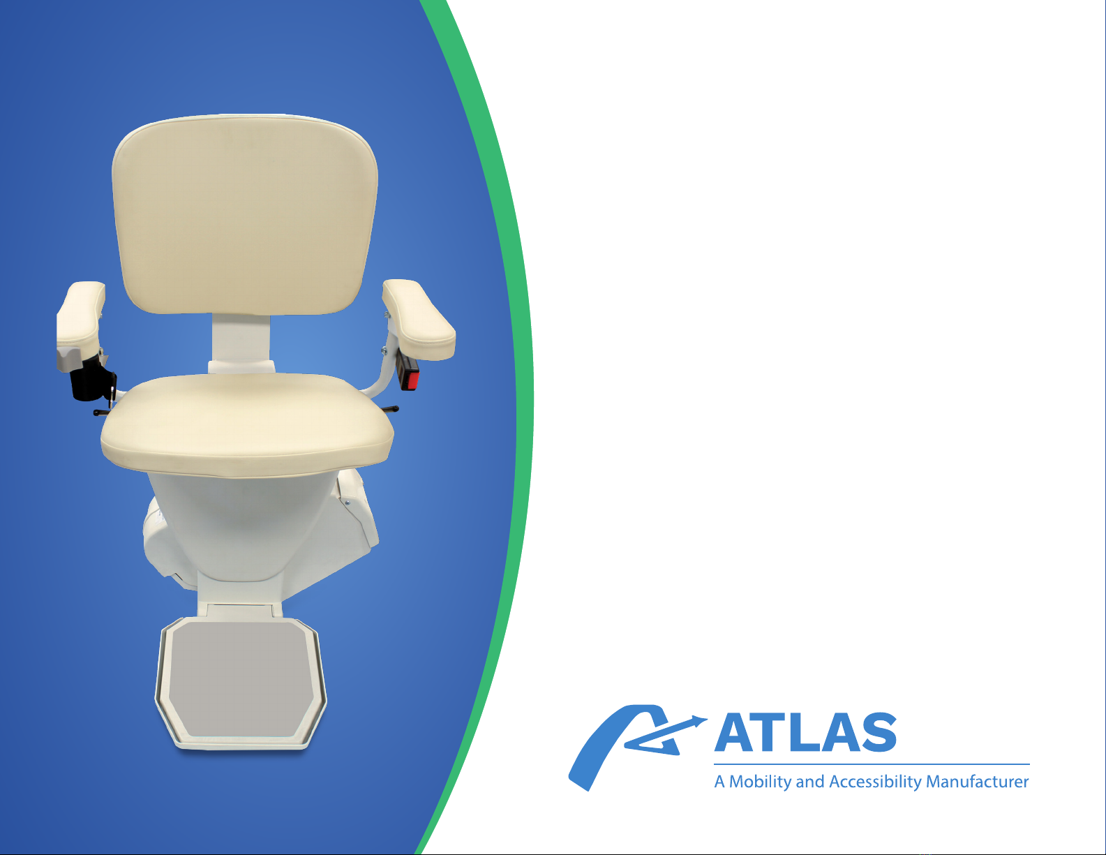
2. Measure the overall length of the stairs from the nose
at the top landing of the stairs to the oor at the bottom
(nose to oor measurement). See Figure 4-1.
3. For a normal stairway with adequate space for a landing,
add 7" to the nose to oor measurement. This will
provide enough rail length to allow the stair lift to be
adjusted so that the oor-to-seat height will be the
same at both the top and bottom.
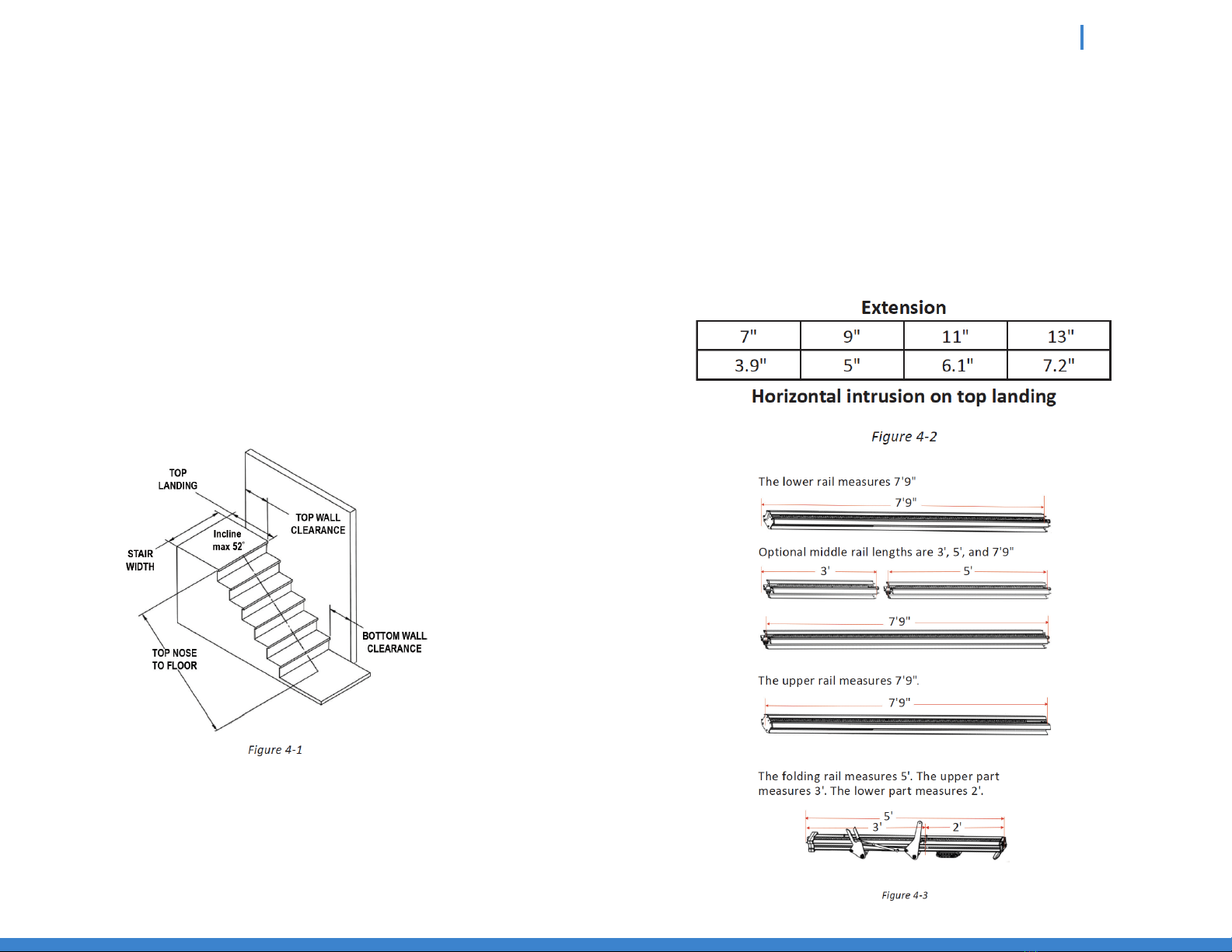
4. If the top landing has restrictions (i.e. a wall or
doorway), use the chart to determine the length of
extension that should be used. See Figures 4-2 and 4-3.
RAVE 2 INSTALLATION MANUAL INSTALLATION
6
NOTE: Do not cut rail inside the house (aluminum chips are
very difcult to remove from carpets).
5. To cut the rail, use a standard chop saw with a 12"
blade designed to cut aluminum.
INSTALLATION SITE ELECTRICAL
REQUIREMENTS
The lift must be connected to a dedicated 120V AC 15A
electrical circuit.
RAIL INSTALLATION
1. Open the rail box and remove its contents.
2. Position the bottom rail (the rail with the end plate
attached directly on the stairs with the end plate
towards the bottom of the stairs and the plastic rack
facing up.
Place and object that measures 1/2" between end plate
and the oor. See Figure 4-4.
Do not cut the end of the rail that contains the joint
holes. Remove the charger strips and wire harness
before cutting.
Atlas offers a rail jig that allows holes to be drilled
in the end of a rail.
Contact [email protected]
RAVE 2 INSTALLATION MANUAL INSTALLATION
7
NOTE: Use the chair box, or another heavy object, like a toolbox,
at the bottom of the rail to prevent it from sliding down the stairs.
3. Install two (2) splice bars into the end of the track
containing the splice pins. They will each be secured
by the "joint fasteners" (5/16" athead screws).
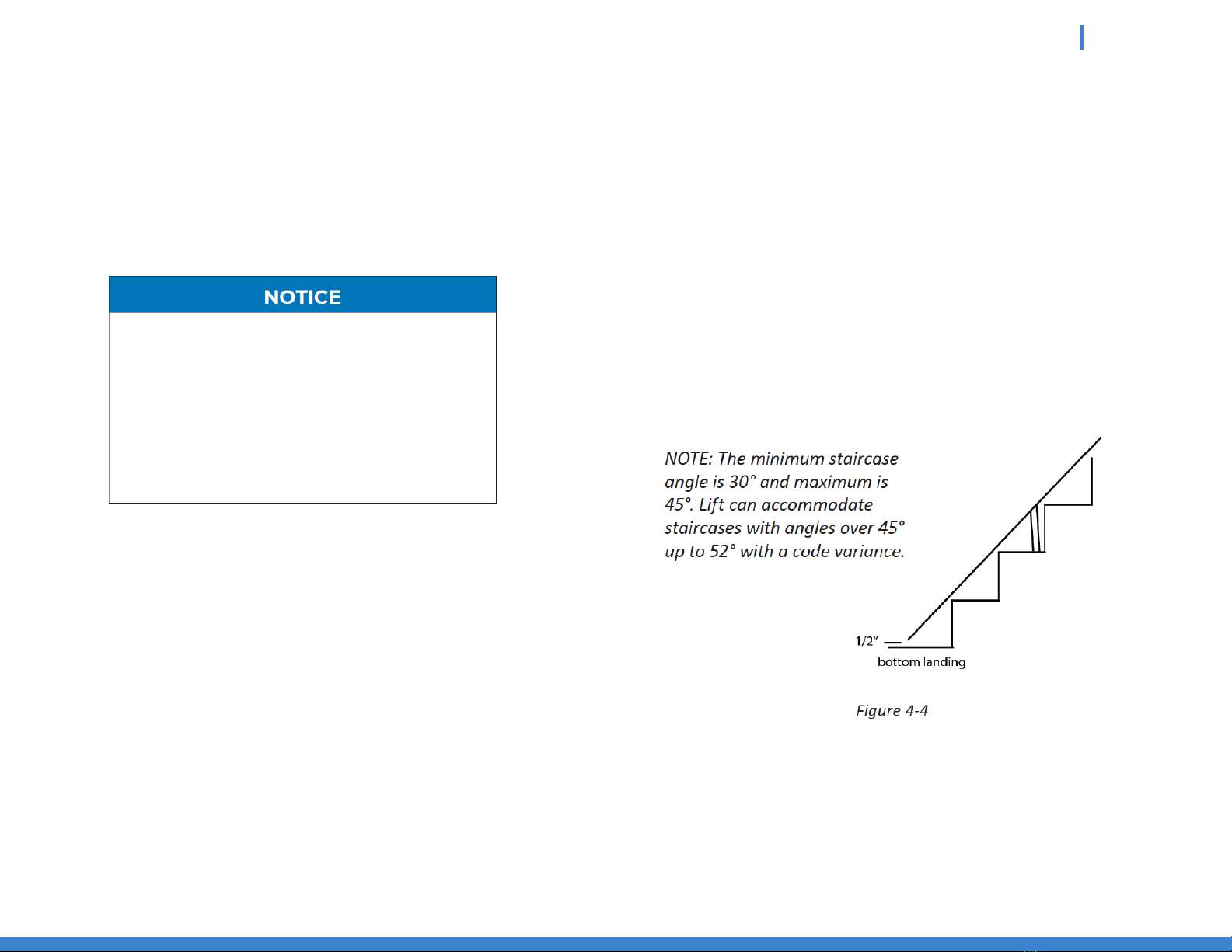
4. Position the two ends of the rail
close together. Locate and connect
the plug on the ends of the two
power harnesses inside the two
rail pieces. See Figure 4-5.
5. With the plastic rack facing up,
slide the top into the bottom rail
and guide them together using
the pre-installed pins. Gently tap
on the top rail if necessary to
get them close together.
Be careful not to pinch the
power harness. See Figure 4-6.
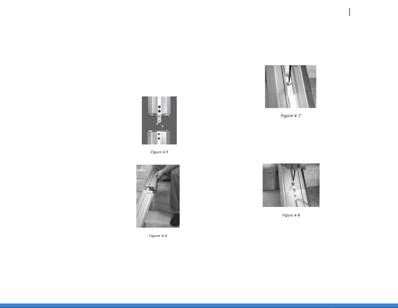
6. Install two (2) joint fasteners and rmly tighten with
3/16" Allen wrench. See Figure 4-7.
7. Turn rail over and install the remaining two (2) joint
fasteners and rmly tighten with 3/16" Allen wrench.
See Figure 4-8.
RAVE 2 INSTALLATION MANUAL INSTALLATION
8
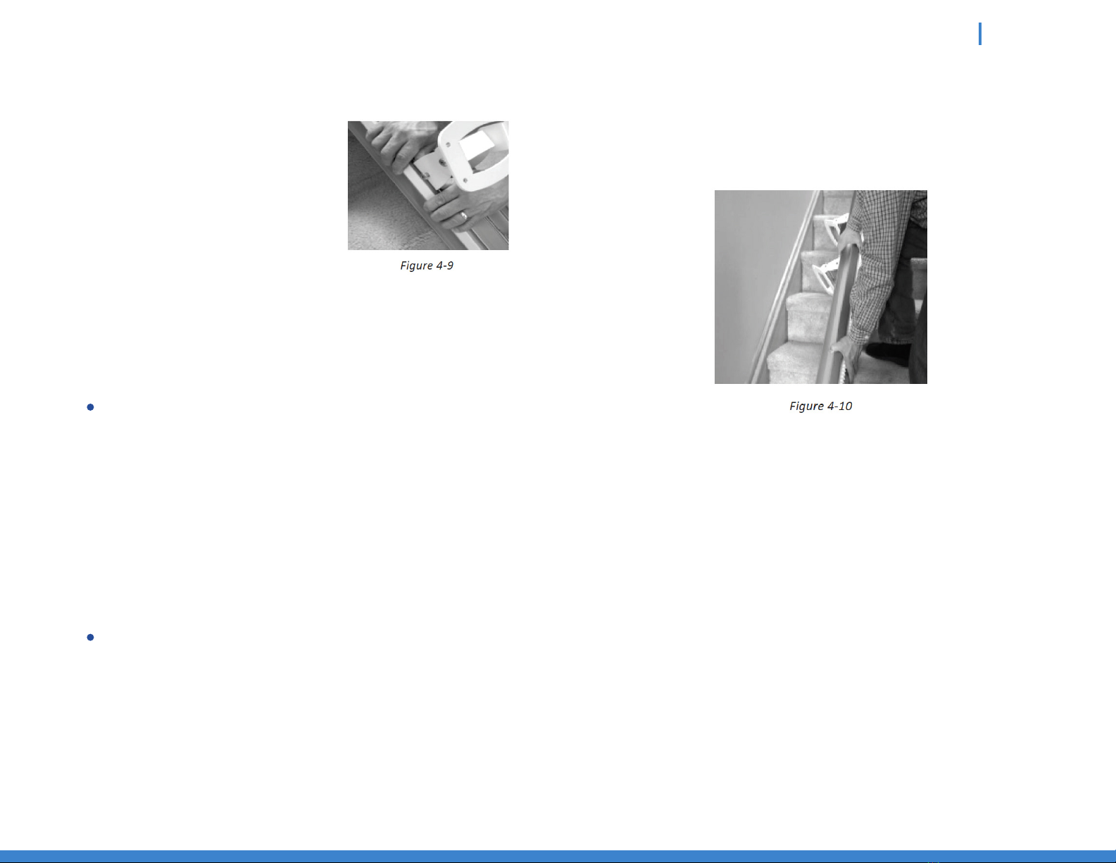
8. Install rail brackets with
label facing the staircase
side by loosening the screws
and snapping each bracket
edge into the slot, or slide
the brackets on from the
top of the rail.
See Figure 4-9.
NOTE: When installing the track brackets, if the rail is upside-down,
the nut side should be facing the middle of the staircase, then if the
rail is ipped over, the nut side will face the wall and so will the label.
For double rails, the rst rail bracket should be
tightened in place so when turned over the back of
the bracket touches the riser of the rst step from
the bottom landing. The second and third brackets
should be placed and tightened on the steps on each
side of the rail joint, again so the back of the bracket
touches the riser of the step. The fourth and nal
bracket should be placed on the last step before the
top landing, again tightening it so it touches the front
of the riser of the last step.
Tighten the rst rail bracket in place so when turned
over the back of the bracket touches the riser of the
rst step from the bottom landing. Place the other
bracket on the last step before the top landing,
again tightening it so it touches the riser of the
last step.
9. Turn the rail right side up (gear rack facing up).
See Figure 4-10.
10. Measure any obstruction form the wall (this may
include handrails, molding, light switches, etc.)
and adjust the edge of the brackets and equal distance
from the wall. The minimum distance will be 1" from
the wall or any other obstruction.
RAVE 2 INSTALLATION MANUAL INSTALLATION

9
11. The underside of the rail must be at least 2" above the
stair tread nose to provide clearance for the footrest.
To achieve this 2" clearance move the rail and bracket
bracket forward. Once the clearance is 2", tighten all
bracket nuts to hold the brackets in position.
To maintain the 2" clearance, and to hold the rail in
place, secure the bottom bracket to the rst step
from the oor with 2" wood screws, using a 3/8" nut
driver on a 6"-10" extension of a cordless drill.
See Figure 4-11.
ZERO INTRUSION INSTALLATION
The lift must be connected to a dedicated 120V AC 15A
electrical circuit.
1. Measure (A) top landing to (B) bottom landing.
See Figure 4-12.
2. 7" of overrun should be added for a normal overrun
with no obstructions within 3.9" of the nose of the top
step. See Figure 4-12.
NOTE: The top rail is normally cut unless the length of travel is short,
less than the length of the bottom rail when the bottom rail will need
to be cut.
RAVE 2 INSTALLATION MANUAL INSTALLATION
Table of contents
Other Atlas Stairlift manuals


