Bravo EVT-4000e User manual

1
EVT-4000e
Maintenance Manual
EVT TECHNOLOGY CO., LTD.

2
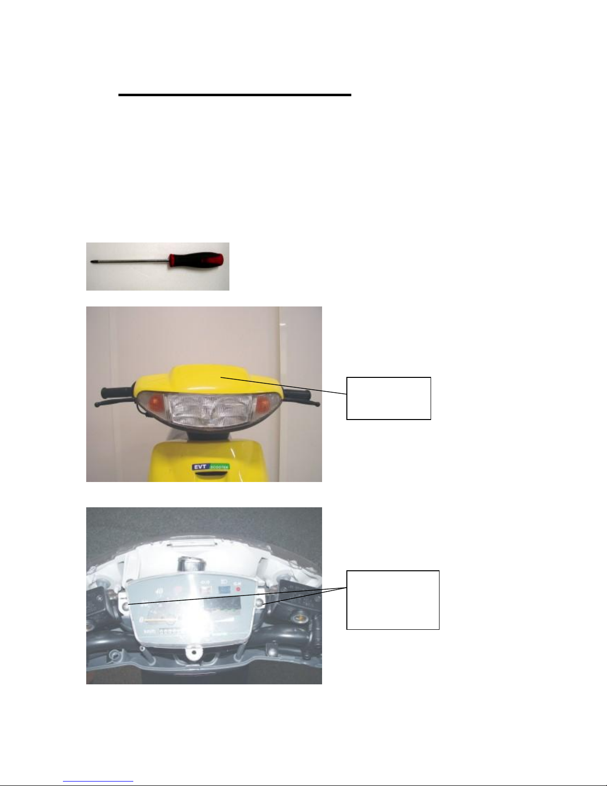
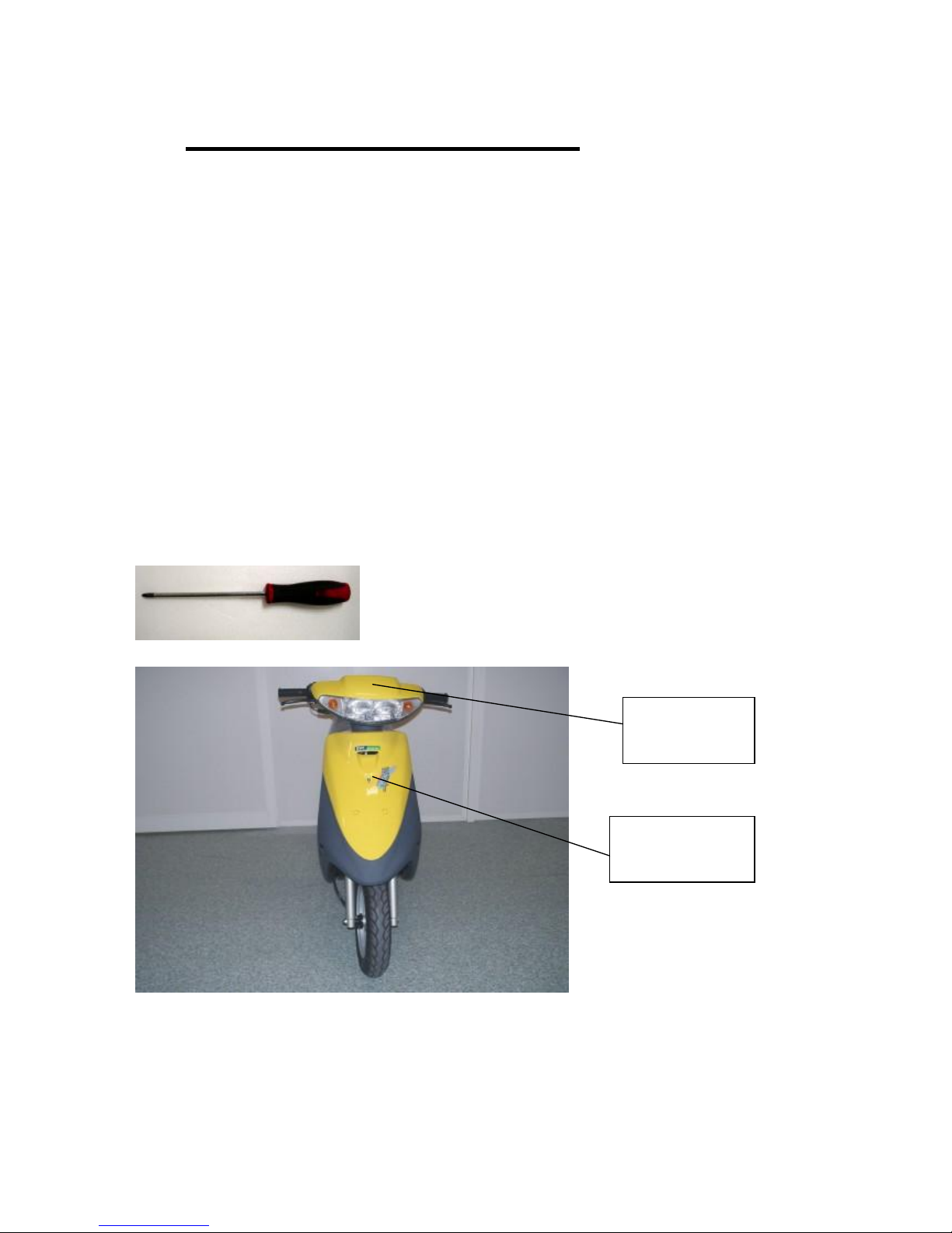
(1) HEAD LIGHT ASSY
Replace Head Light Assy :
(1) Release three screws on the handle cover
(Picture 1)
(2) Release two mounting screws on the instrument panel, and then release three screws
on the head light assy (Picture 2)
(3) Follow with the reversed steps to restore
Tools!"(1) (2) screwdriver
(Picture 1)
Three screws on
the handle cover
Two mounting screws
on the instrument
Three screws on
the head light assy
Signal light bulb set

3
(Picture 2)
Replace Head Light Bulb"
(1) Release three screws on the handle cover
(Picture 1)
(2) Release two mounting screws on the instrument panel so can easily replace the
bulb (Picture 2)
(3) Follow with the reversed steps to restore
Tools! " (1) (2) screwdriver
Replace Signal Light Bulb"
(1) Release three screws on the handle cover
(Picture 1)
(2) Release signal light bulb set for replacement
(Picture 2)
(3) Follow with the reversed steps to restore
Tools! " (1) screwdriver
4
(2) SPEEDOMETER ASSY
Replace Instrument Panel :
(1) Release three screws on the handle cover (Picture 1)
(2) Release two mountingscrews on the instrument panel (Picture 2)
(3) Release the nut for the speedometer (Picture 3)
(4) Follow with the reversed steps to restore
Tools>:(1) (2) screwdriver
(Picture1)
(Picture2)
Three screws on
the handle cover
Twomounting
screws on the
instrument panel
5
(Picture3)
Replace SpeedometerCable:
(1) Release three screws on the handle cover
(Picture 1)
(2) Release two mountingscrews on the instrument panel
(Picture 2)
(3) Release the nut for the speedometer
(Picture 3)
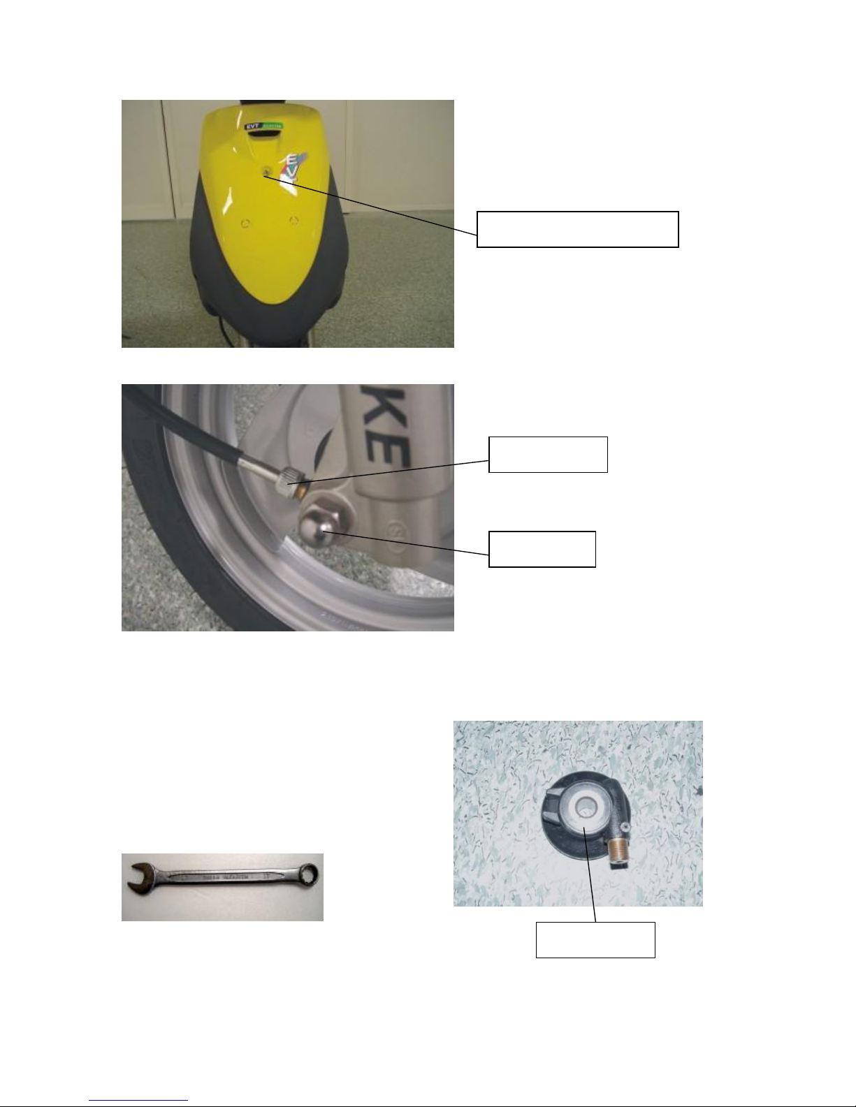
(4) Release three screws on the front cover
(Picture 4)
(5) Release speedometer nut on the front wheel
(Picture 5)
(6) Follow with the reversed steps to restore
Tools>:(1) (2) (4) screwdriver
Speedometer bolt
Speedometer nut
Speedometer cable
6
(Picture4)
(Picture5)
Replace SpeedometerGear:
(1) Release front axle nut
(Picture 5)
(2) Remove the front wheel
(3) Follow with the reversed steps to restore
Tools>:(1) box wrench(17mm)
Three screws on the front cover
Speedometer nut
Front axle nut
Speedometer gear

7
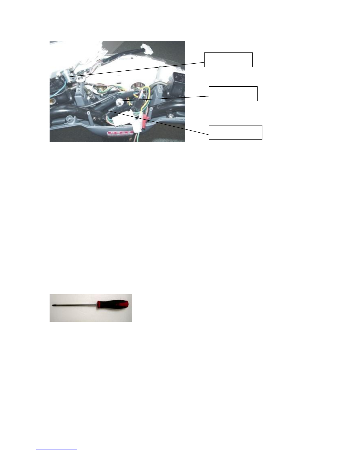
(3) KEYSWITCH AND HORN
Replace Key Switch :
(1) Release three screws on the front cover
(Picture 1)
(2) Release sixscrews on the front fender
(Picture 1)
(3) Release three screws on the glove box
(Picture 2)
(4) Release 4 pin connector and two screws on the keyswitch
(Picture 3)
(5) Follow with the reversed steps to restore
Tools>:(1) (2) screwdriver;(3) T-bend socket wrench(8mm)& screwdriver;
(4) T-bend socket wrench(10mm)
(Picture1)
Three screws on the
front cover
Six screws on the
front fender
8
(Picture2)
(Picture3)
Three screws on
the glove box
Two screwsfor the key
switch on left and right side
4 pin connector
9
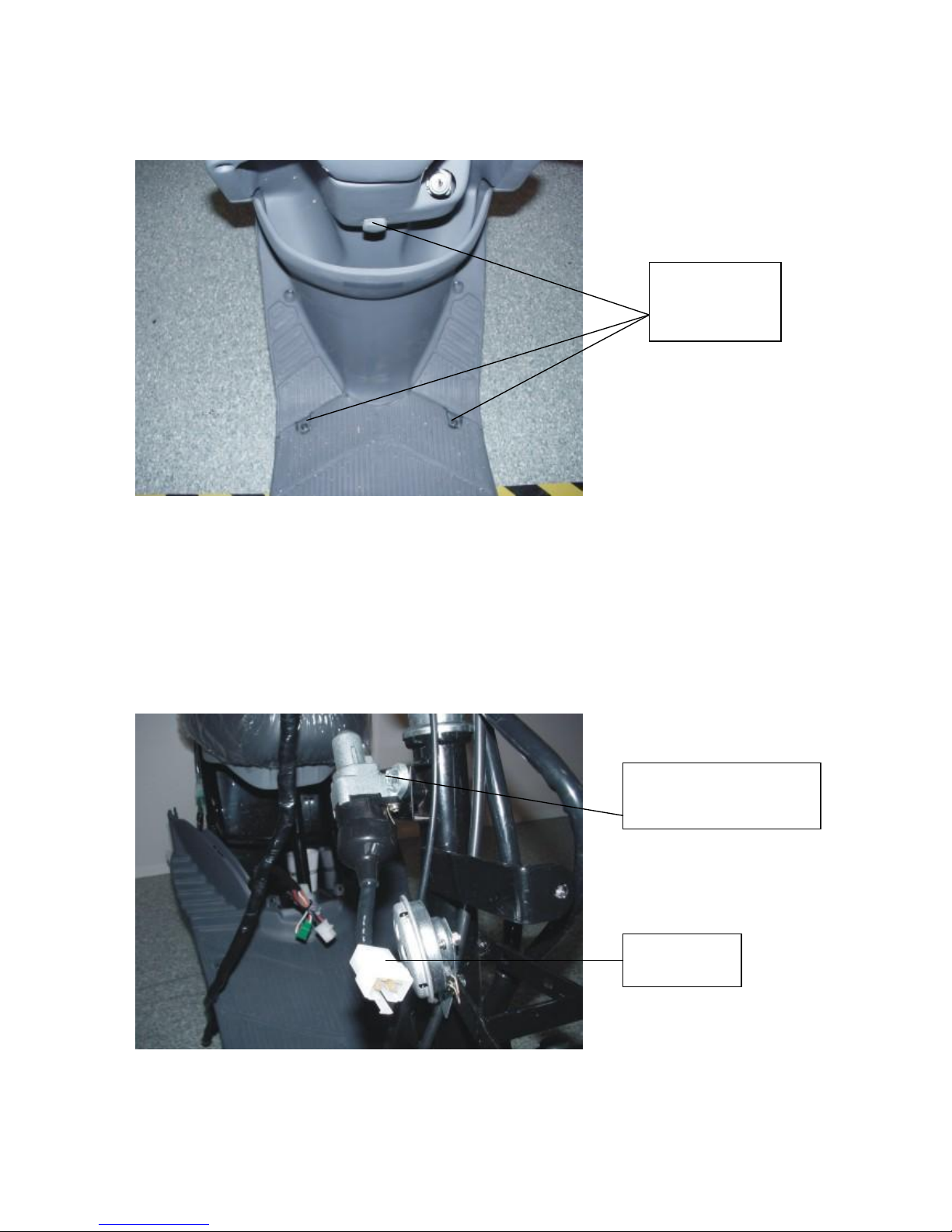
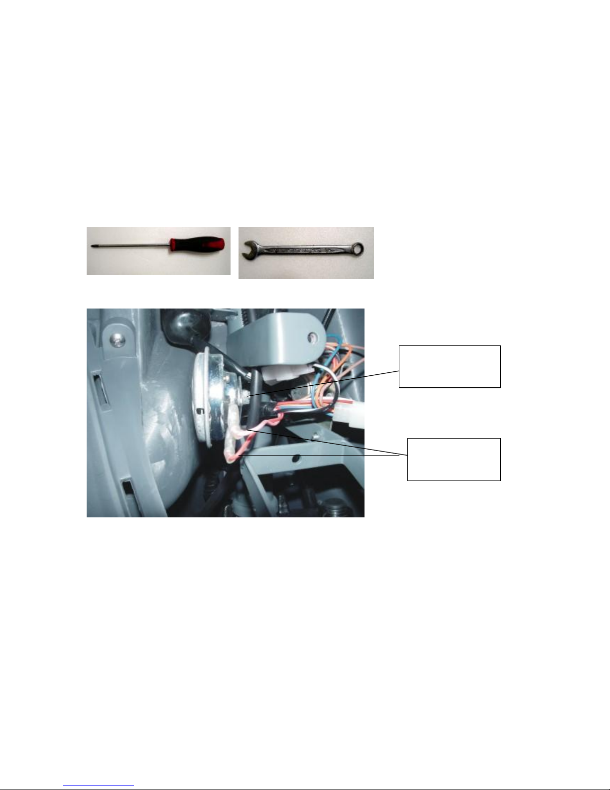
Replace Horn:
(1) Release three screws on the front cover
(Picture 1)
(2) Release two connectors on the horn
(Picture 2)
(3) Release the mounting screws on the horn
(Picture 4)
(4) Follow with the reversed steps to restore
Tools>:(1) screwdriver;(3) open-end wrench(10mm)
(Picture4)
Two connectors on
the horn
Two mounting screws
on the horn
10
(4) MAIN CONTROLCORD
Replace Main Control Cord :
(1) Release three screws on the handle cover, two mountingscrews on the instrument panel,
three screws on the head light, three screws on the front cover and two screws on the right
trim
(Picture 1 & 2)
(2) Release all of the connectors stored inside the handle cover
(Picture 3)
(3) Release all of the connectors stored inside the front cover
(Picture 4)
(4) Release all of the connectors stored inside the right cover
(Picture 5)
(5) Follow with the reversed steps to restore
Tools>:(1) screwdriver
(Picture1)
Three screws on
the handle cover
Three screws on the
front cover

11
(Picture2)
Connectors inside the handle cover
(Picture3)
Twomounting
screws on the
instrument panel
Three screws on
the head light
6 pin connector for the
head light assy
6 pin connector for left
handle switch
Connectors for
power cut off and
brake functions
4 pin connector for right
handle switch
3 pin connector for
E/Pswitch
12 pin connector for
speedometer assy
2 pin connector for
flasher relay
2 pin connector for
Instrument panel
light
12
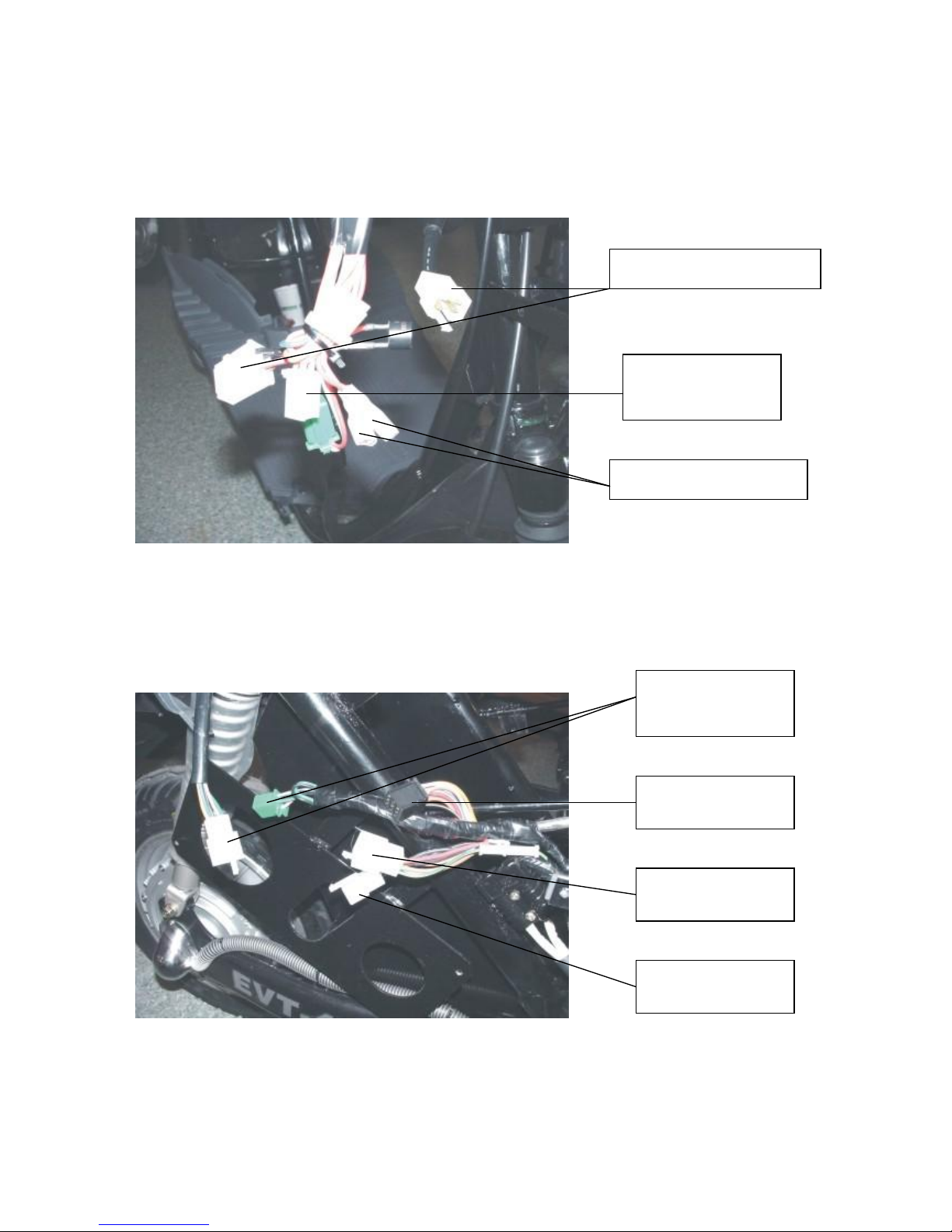
Connectors inside the front cover
(Picture4)
Connectors inside the rightcover
(Picture5)
4 pin connector for keyswitch
Two connectors for the horn
4 pin connector
for DC
to DC converter
6 pin connector for the
tail light assy
9 pin black connector
9 pin white connector
2 pin white connector

13
Replace FlasherRelay:
(1) Release three screws on the handle cover, remove the rubber sleeve so can see the 2 pin
connector for the flasher relay
(Picture 1 & 6)
(2) Follow with the reversed steps to restore
Tools>:(1) screwdriver
(Picture6)
Rubber sleeve and 2 pin
connector for flasher
relay

14
(Picture7)
Replace DC to DC converter:
(1) Release three screws on the front cover so can see the DC to DC converter
(Picture 7)
(2) Release two screws and 4 pin connector for the DC to DC converter
(Picture 7 & 8)
(3) Follow with the reversed steps to restore
Tools>:(1) (2) screwdriver
(Picture8)
DC to DC
converter
4 pin connector for DC to DC
converter
15
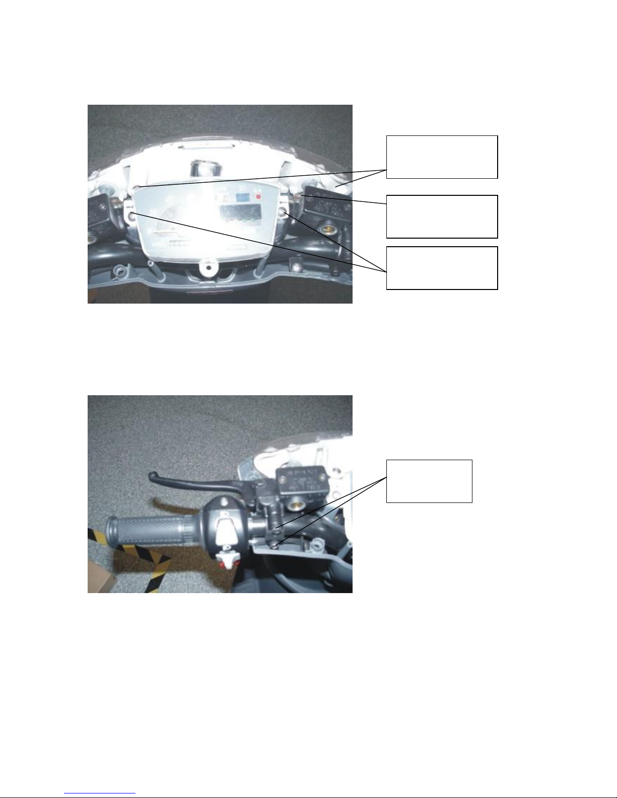
(5) HANDLESWITCH LEFTAND RIGHT
Replace Left Handle Switch:
Remove left rear view mirror and release three screws on the handle cover
(Picture 1)
(1) Release two mountingscrews on the instrument panel
(Picture 1)
(2) Release two screws on the left handle switch
(Picture 1)
(4) Follow with the reversed steps to restore
Tools>:(1) open-end wrench(14mm)& screwdriver;(2) (3) screwdriver
(Picture1)
Twomounting
screws on the
instrument panel
Two screws on the
left handle switch
16
Replace Right Handle Switch:
(1) Remove the right rear mirror and three screws on the handle cover
(Picture 2)
(2) Release two mountingscrews on the instrument panel
(Picture 1)
(3) Release two screws on the right handle switch andone screw for the throttle cable
(Picture 2)
(4) Follow with the reversed steps to restore
Tools>:(1) open-end wrench(14mm)& screwdriver;(2) (3) screwdriver
(Picture2)
Twomounting screws on
the right handle switch
The screwfor the
throttle cable

17
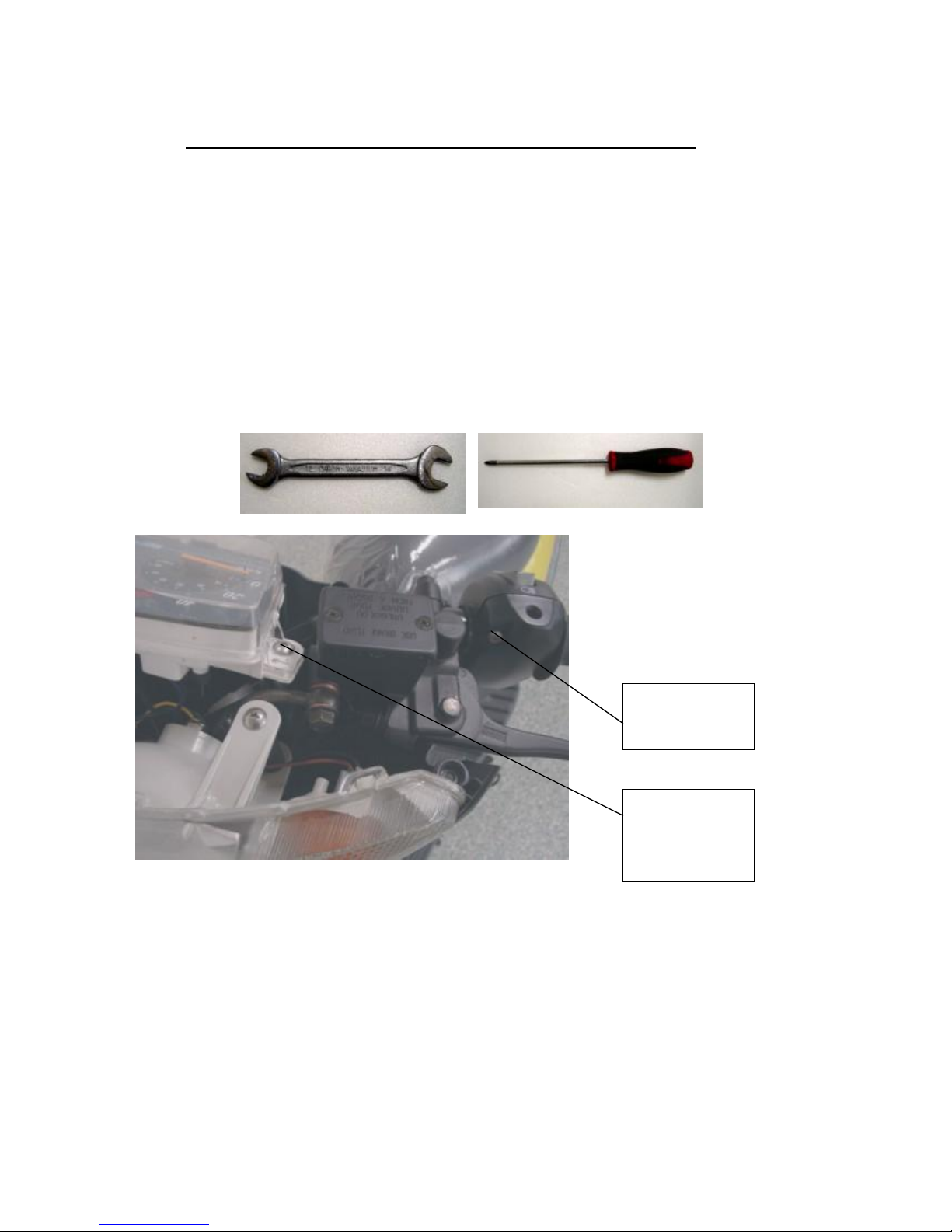
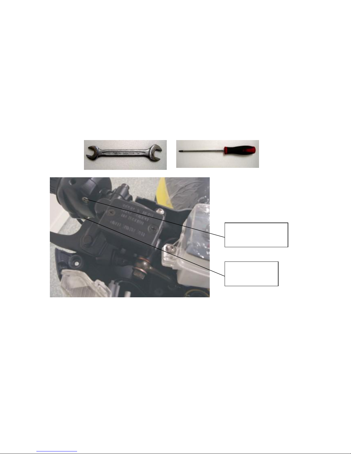
(6) BRAKE MASTER CYLINDER R & L
Replace MasterCylinderRight and Left:
(1) Release three screws on the handle cover, two mountingscrews on the instrument panel
and three screws on the head light assy
(Picture 1 & 2)
(2) Check the fluid in reservoir for refuel or replace the brake fluid
(Picture 2)
(3) Replace reservoir
(a) Gasket fail or wear out (b) leaking
(4) Release the screw on thebrake hose
(Picture 2)
(5) Release two screws on the reservoir
(Picture 3)
Tools>:(1) screwdriver;(4) box wrench(12mm); (5) hex-key wrench(5mm)
(Picture1)
Three screws on the
handle cover
18
(Picture2)
(Picture3)
Three screws on the head
light assy
Twomounting screws on
the instrument panel
Two screws
on the
reservoir
The screwon the brake
hose

19
(7) FRONTFORKAND REAR
SHOCK ABSORBER
Replace Front Fork:
(1) Release three screws on the front cover
(Picture 1)
(2) Release sixscrews on the front fender
(Picture 2)
(3) Release three screws on the glove box
(Picture 3)
(4) Release clampingscrew for the handle
(Picture 4)
(5) Release front axle nut to remove the wheel
(Picture 5)
(6) Release two screws on the caliper
(Picture 6)
(7) Release two screws on the front fork and check the steel balls to see if theyare
missing (Picture 4)
(8) Properlyadjust the front fork clearance and follow the reversed steps to restore
Tools>:(1) (2) screwdriver;(3) T-bend socket wrench(8mm)& screwdriver;
(4) box wrench(14mm); (5) box wrench(17mm); (6) Y-bend socket wrench(12mm);
(7) special wrench

20
(Picture1)
(Picture2)
Three screws on
Six screws on
the front fender
Table of contents
Other Bravo Scooter manuals


