Bray/VAAS Slurry 760 Series User manual
Bray/VAAS
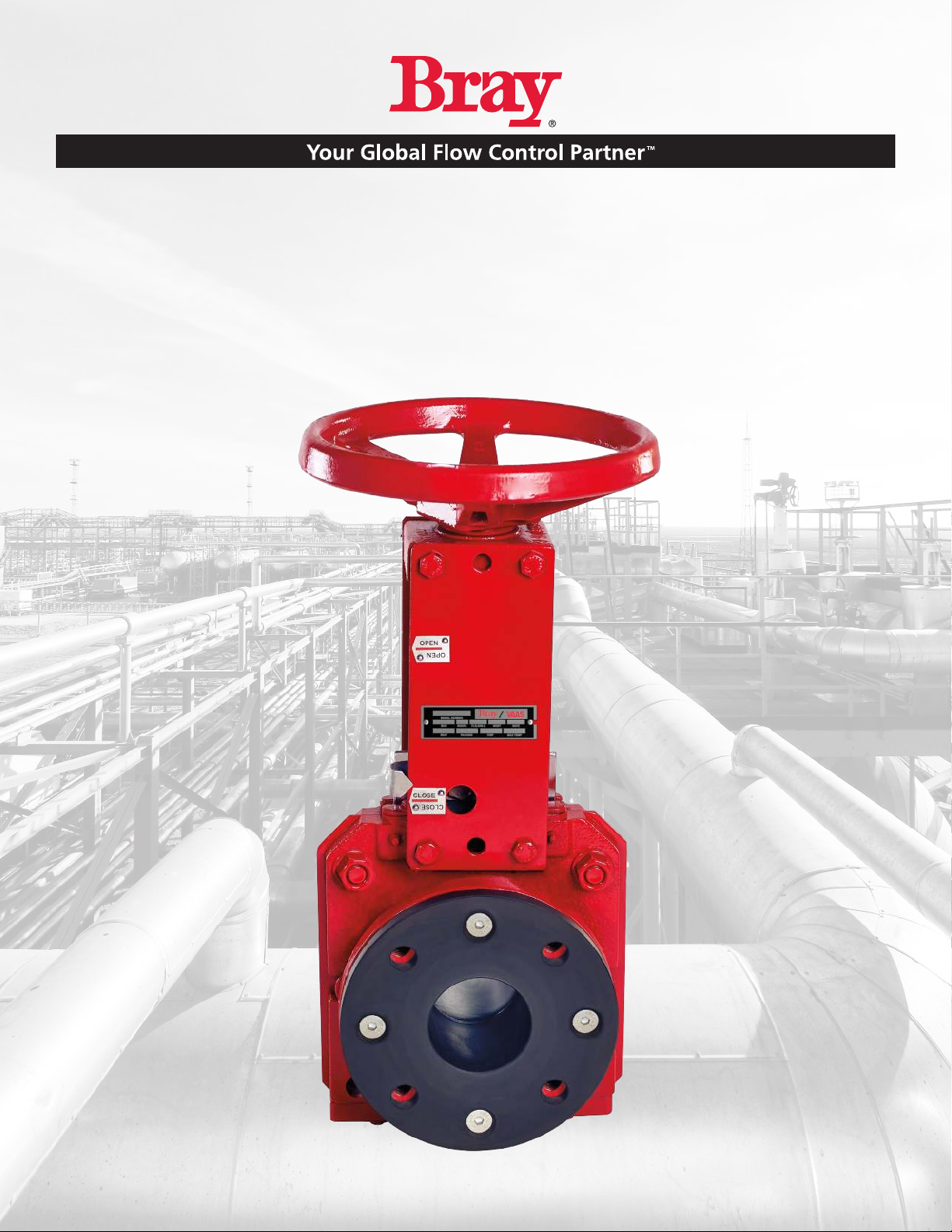
Slurry Series Knife Gate Valve
760/762/765/766/767/768 Series
Operation and Maintenance Manual

Table of Contents
Definition of Terms . . . . . . . . . . . . . . . . . . . . . . . . . . . . . . . . . . 1
Safety Instructions. . . . . . . . . . . . . . . . . . . . . . . . . . . . . . . . . . . 1
Introduction. . . . . . . . . . . . . . . . . . . . . . . . . . . . . . . . . . . . . . 2
Unpacking . . . . . . . . . . . . . . . . . . . . . . . . . . . . . . . . . . . . . . 2
Storage . . . . . . . . . . . . . . . . . . . . . . . . . . . . . . . . . . . . . . . . 2
Installation . . . . . . . . . . . . . . . . . . . . . . . . . . . . . . . . . . . . . . 3
Commissioning . . . . . . . . . . . . . . . . . . . . . . . . . . . . . . . . . . . . 3
Cylinder-Operated Valves . . . . . . . . . . . . . . . . . . . . . . . . . . . . . 3
Manual Valves . . . . . . . . . . . . . . . . . . . . . . . . . . . . . . . . . . . 3
Valve Maintenance . . . . . . . . . . . . . . . . . . . . . . . . . . . . . . . . . . 4
Lubrication . . . . . . . . . . . . . . . . . . . . . . . . . . . . . . . . . . . . 4
Secondary Seal Replacement . . . . . . . . . . . . . . . . . . . . . . . . . . . 4
Manual Valves . . . . . . . . . . . . . . . . . . . . . . . . . . . . . . . . . 5
Cylinder-Operated Valves . . . . . . . . . . . . . . . . . . . . . . . . . . . 5
Stroke Length Tables . . . . . . . . . . . . . . . . . . . . . . . . . . . . . . 6
Seat Replacement (Series 760, 762, and 767) . . . . . . . . . . . . . . . . . . . 7
Seat Replacement (No Retainer - Series 765, 766 & 768) . . . . . . . . . . . . . 8
Actuator Maintenance . . . . . . . . . . . . . . . . . . . . . . . . . . . . . . . . 8
Spare Parts . . . . . . . . . . . . . . . . . . . . . . . . . . . . . . . . . . . . 9
Troubleshooting. . . . . . . . . . . . . . . . . . . . . . . . . . . . . . . . . . . . 9
For information on this product and other Bray products please visit us at our web page - www.bray.com.
Slurry Series
Operation and Maintenance Manual
1
Slurry Series
Operation and Maintenance Manual
Definition of Terms - Safety Instructions
READ AND FOLLOW THESE INSTRUCTIONS
SAVE THESE INSTRUCTIONS
DEFINITION OF TERMS
Indicates a potentially hazardous situation which, if not avoided, could result in death or
serious injury.
Indicates a potentially hazardous situation which, if not avoided, may result in minor or
moderate injury.
NOTICE Used without the safety alert symbol indicates a potential situation which, if not avoided,
may result in an undesirable result or state, including property damage.
HAZARD-FREE USE
This device left the factory in proper condition to be safely installed and operated in a hazard-free manner. The notes and
warnings in this document must be observed by the user if this safe condition is to be maintained and hazard-free opera-
tion of the device assured.
Take all necessary precautions to prevent damage to the valve due to rough handling, impact, or improper storage. Do not
use abrasive compounds to clean the valve, or scrape metal surfaces with any objects.
The control systems in which the valve is installed must have proper safeguards to prevent injury to personnel, or damage to
equipment, should failure of system components occur.
QUALIFIED PERSONNEL
• A qualified person in terms of this document is one who is familiar with the installation, commissioning, and operation
of the device and who has appropriate qualifications, such as:
• Is trained in the operation and maintenance of electrical equipment and systems in accordance with established safety
practices
• Is trained or authorized to energize, de-energize, ground, tag, and lock electrical circuits and equipment in accordance
with established safety practices
• Is trained in the proper use and care of personal protective equipment (PPE) in accordance with established safety
practices
• Is trained in first aid
• In cases where the device is installed in a potentially explosive (hazardous) location – is trained in the commissioning,
operation, and maintenance of equipment in hazardous locations
2
Slurry Series
Operation and Maintenance Manual
The valve must only be installed, commissioned, operated, and repaired by qualied personnel.
The device generates a large mechanical force during normal operation.
All installation, commissioning, operation, and maintenance must be performed under strict observation of all applicable
codes, standards, and safety regulations.
Observe all applicable safety regulations for valves installed in potentially explosive (hazardous) locations.
INTRODUCTION
The Bray/VAAS Series 760/762/765/766/767/768 provides repeatable bidirectional shutoff in a rugged, cast body.
Additional information about Slurry Series valves – including application data, engineering specifications, and actuator
selection is available from your Bray distributor or sales representative.
UNPACKING
Ensure the box is not damaged externally. Remove the valve from the packaging and check for any damage to the valve
and its components during transit.
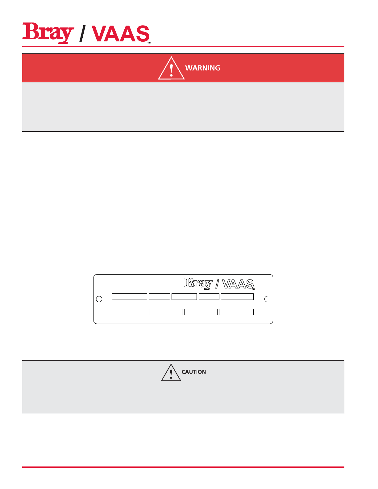
Valve size and brief material specification of body (markings such as “SS” or “DI”) are marked on the valve body. Stainless
steel nameplate (below) fixed on to the yoke of valve contains most of the relevant information on the valve including Bray/
VAAS work order number and unique serial number of the valve. These details should be quoted for all requirements of
service and spares.
SERIAL NUMBER
SIZE MODEL FLG. DRILL BODY GATE
SEAT PACKING CWP MAX TEMP
STORAGE
Wrap the valve with a polyethylene cover. Cover the ports for pneumatic actuator/accessories with plastic caps. Store
these valves in the same packing indoors and without direct exposure to the environment.
If the valve is to be stored for a long period of time before installation, it should be stored in a vertical position (preferable) and
in a cool, clean area to prevent damaging effects on the packing.
Gate should be off the seat to prevent compression set.

3
Slurry Series
Operation and Maintenance Manual
INSTALLATION
• Valves can be mounted with flow in both directions.
• Install the valve between flanges using fasteners.
Support should be used for valves size 8” and over when installed in vertical pipe. Failure to do so can result in improper
valve operation and/or valve failure.
COMMISSIONING GUIDELINES
Cylinder Operated Valves
1. Connect instrument quality air, preferably through an air filter/regulator of adequate size. The recommended air pres-
sure is 80-120 psi (5-8 bar). Refer to the appropriate bulletin/drawing for port and cylinder size details.
2. Ensure the supply air is free from moisture, dirt, and other foreign particles. Drain the filter regulator before operating
the actuator so that pipe rust and dirt if any in the air line will be removed before actuation.
3. If valves are supplied with electrical accessories like limit switch and solenoid valve, ensure wiring is done as per local
electrical safety codes and regulations. Ensure correct electrical supply is given to electrical accessories for proper func-
tioning and safety of the equipment.
4. Open the valve by energizing the solenoid valve/giving air supply to cylinder and operate the valve 2-3 times.
Manual valves
Open/Close the valve manually and observe valve operation.
Wrong electrical supply to accessories will damage the equipment. Do not over tighten the gland nuts as this may cause
excessive friction and premature damage to packing.

4
Slurry Series
Operation and Maintenance Manual
MAINTENANCE
NOTICE
Any modification or use of unauthorized parts voids any and all warranty considerations.
Lubrication
The manual valve stem should be lubricated at regular intervals for smooth operation of the valve. A lubrication nipple is
provided on the collar. Cylinder operated valves do not require routine lubrication.
NOTICE
If the cylinder actuator is disassembled for repair, the cylinder wall and seals need to be lubricated with a lithium-based
grease prior to reassembly.
Manual Valve Stem Cylinder Actuator
Secondary Seal Replacement
(Applicable to Series 765, 766, 767, and 768)
1. Relieve the line pressure.
2. Fully close the valve.
3. Ensure the line is empty, and flush if necessary.

5
Slurry Series
Operation and Maintenance Manual
Manual Valves
1. Disconnect the stem from the gate by removing the clevis bolt and nuts
2. Rotate the Hand wheel counter clockwise by holding the stem from
rotation, so that stem retracts fully from the gate.
3. If valves are supplied with bellows, ensure stem is not rotating, as rota-
tion will damage the bellows.
4. Remove the secondary seal retainer bolts (6).
5. Remove the seal retainer (5), wiper (4) (if applicable) and old sec¬ondary
seal (3) from the packing chamber, using a long thin tool to pry it out.
6. Insert the new secondary seal (3) into the packing chamber.
7. Re-attach the wiper (4), if applicable, and secondary seal retainer (5)
onto the valve body.
8. Tighten the secondary seal retainer bolts (6).
9. Lower the stem by rotating the hand wheel clockwise while holding
the stem and fasten the stem to the gate with nuts & bolts.
10. Adjust the gate positions from top of the body according to the follow-
ing tables.
Cylinder-Operated Valves
1. Switch off the electrical supply to the solenoid and limit switches.
2. Remove the cylinder tubing and vent the air inside the cylinder.
3. Disconnect the piston rod from the gate by removing the clevis
bolts & nuts.
4. Apply air slightly to the bottom port of the actuator so that the
piston rod is retracted from the gate.
5. Remove the actuator assembly from the valve by removing the
fasteners connecting the yokes to the valve body.
6. Remove the secondary seal retainer bolts (6).
7. Remove the seal retainer (5), wiper (4), if applicable and old
sec¬ondary seal (3) from the packing chamber, using a long thin
tool to pry it out.
8. Insert the new secondary seal (3) into the packing chamber.
9. Re-attach the wiper (4), if applicable, and secondary seal retainer
(5) onto the valve body.
10. Tighten the secondary seal retainer bolts (6).
11. Mount the actuator and superstructure on the valve.
12. Connect the gate (2) and stem by clevis bolts and nuts
13. Apply air slightly for cylinder operated valves to lower the piston rod and fasten the gate.
14. Adjust and ensure the gate positions from top of the body according to the following tables as appropriate.
With Seal Retainer
Without Seal Retainer
6
Slurry Series
Operation and Maintenance Manual
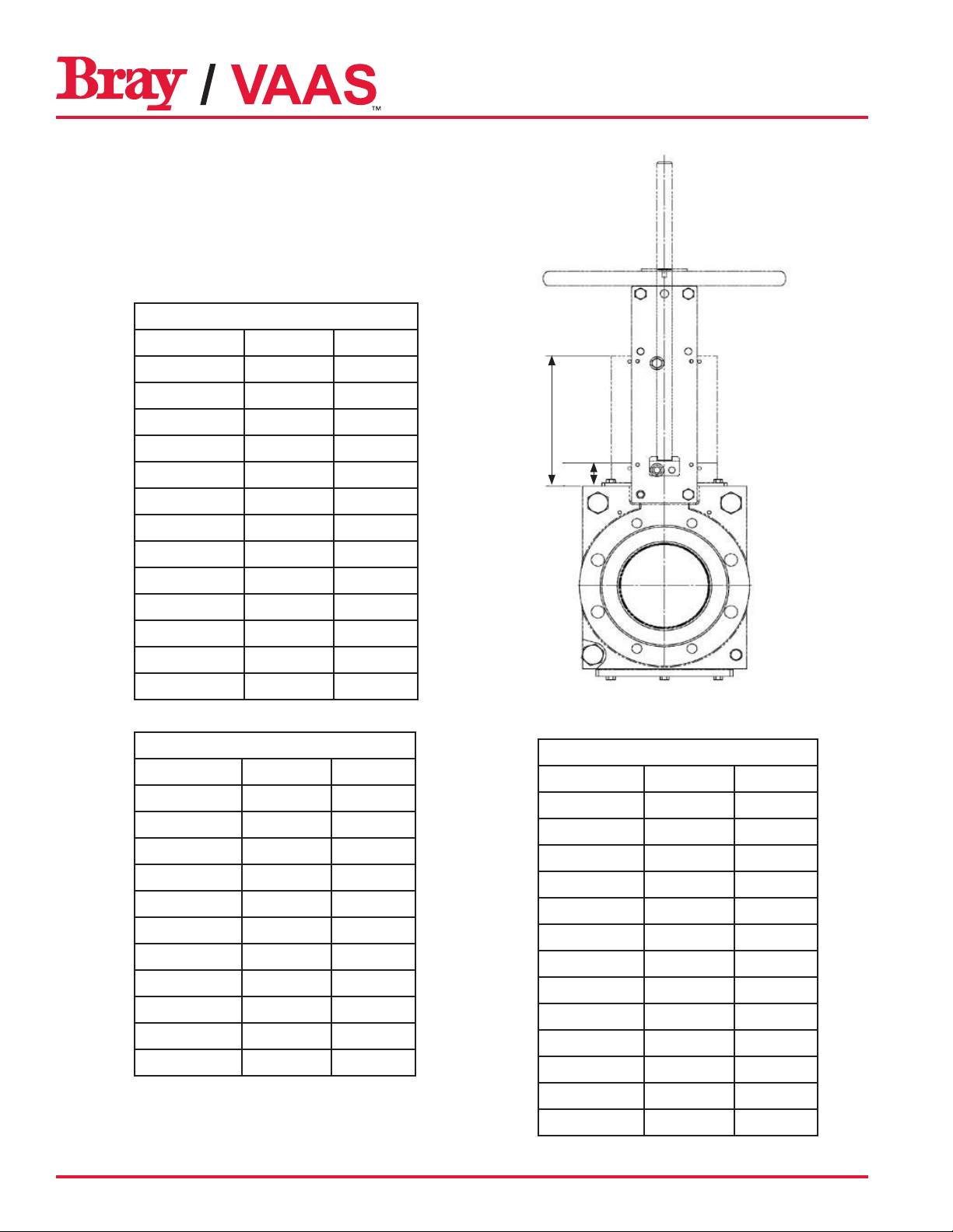
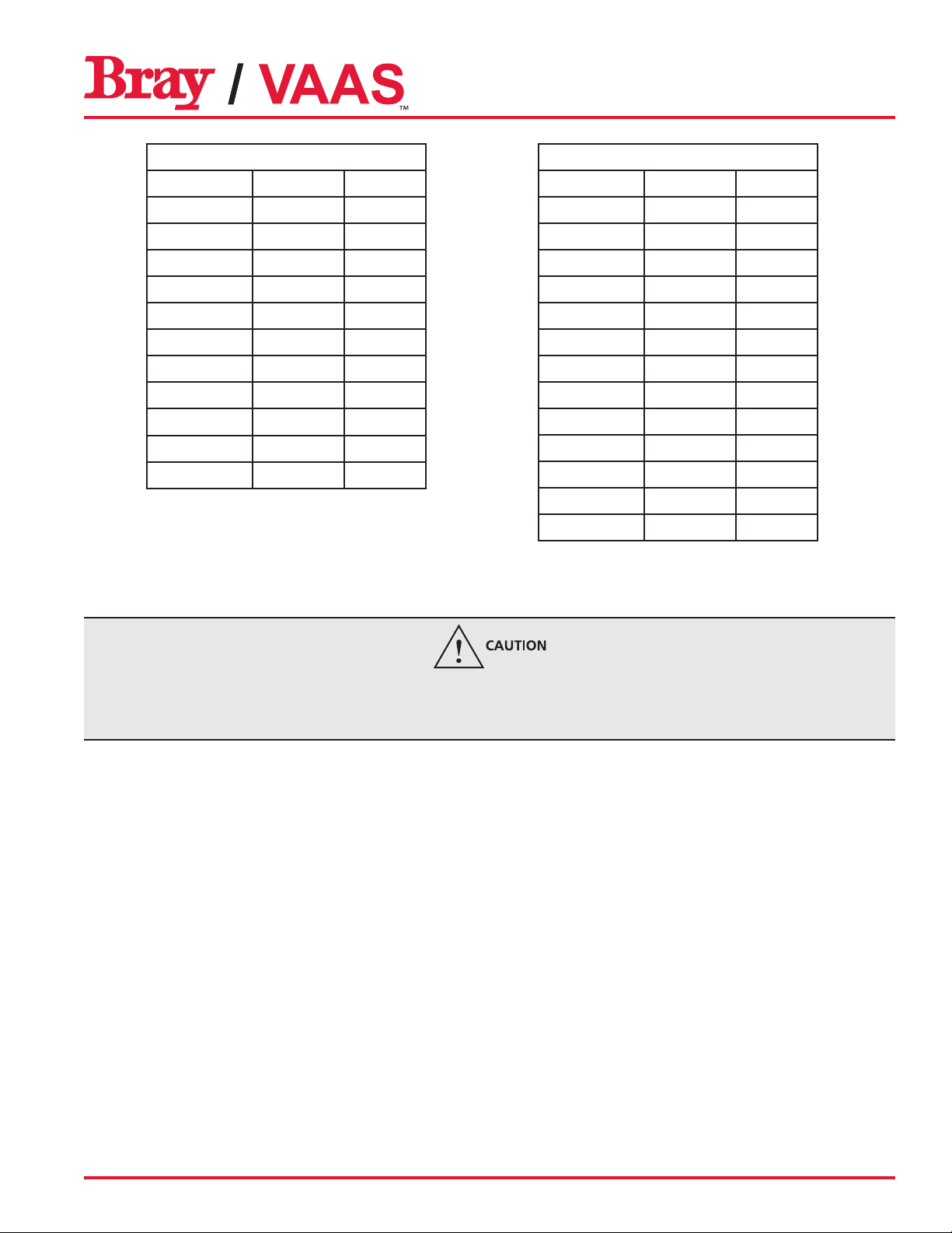
Series 760
Valve Size A (mm) B (mm)
50 38 126
80 36 149
100 37 175
125 41 221
150 49 247
200 38 283
250 48 352
300 47 414
350 67 483
400 55 498
450 65 571
500 77 642
600 74 772
Series 762
Valve Size A (mm) B (mm)
80 43 165
100 74 204
150 55 258
200 60 310
250 62 362
300 57 412
350 89 489
400 71 516
450 81 575
500 70 605
600 83 763
Series 765 & 766
Valve Size A (mm) B (mm)
50 41 117
80 41 149
100 41 180
125 41 210
150 42 232
200 44 289
250 47 350
300 53 414
350 65 475
400 62 522
450 54 587
500 61 632
600 90 810
B
A
Stroke Length Tables
7
Slurry Series
Operation and Maintenance Manual
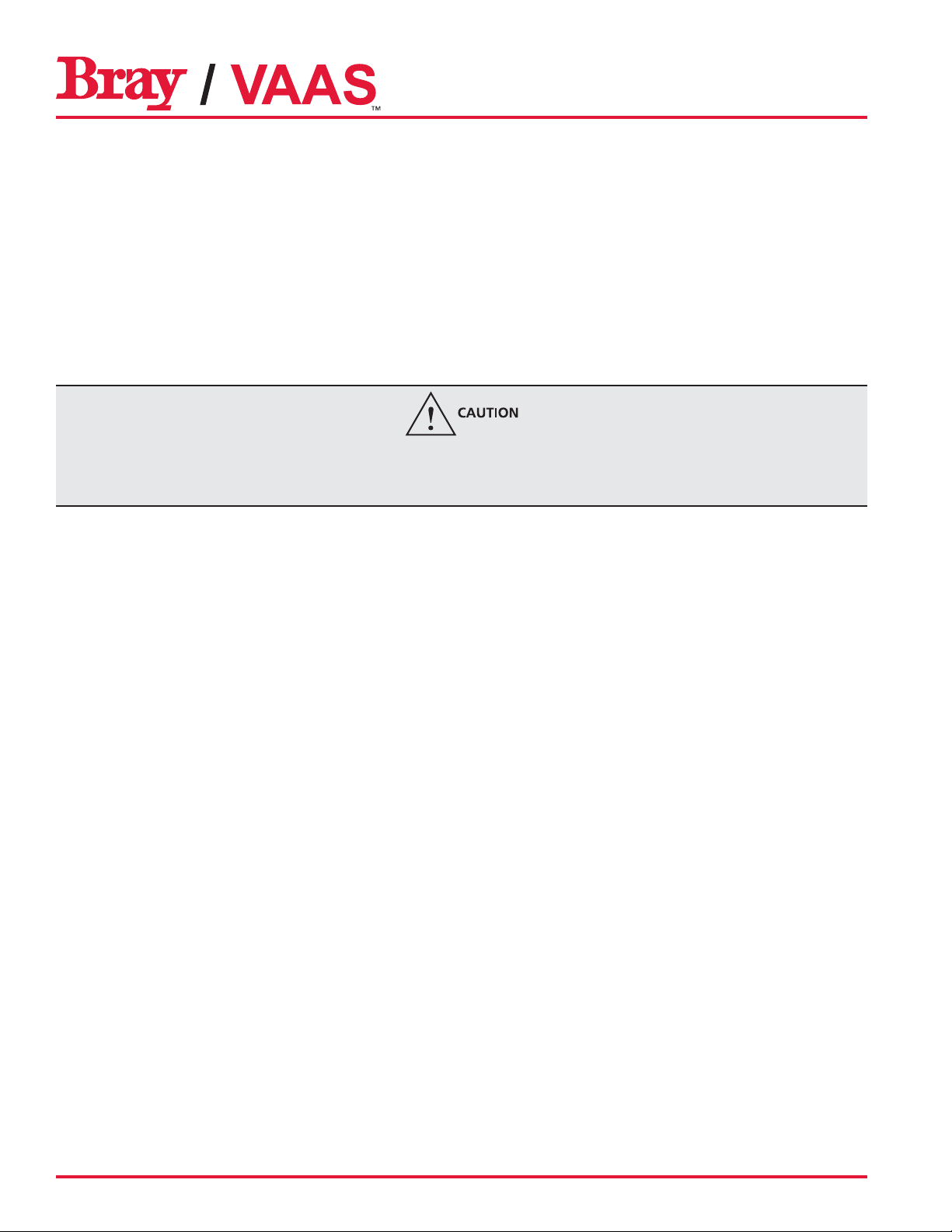
Series 767
Valve Size A (mm) B (mm)
80 54 134
100 54 209
150 63 263
200 75 315
250 64 369
300 75 445
350 73 473
400 97 547
450 82 587
500 80 620
600 109 774
Series 768
Valve Size A (mm) B (mm)
50 32 112
80 32 151
100 37 181
125 44 219
150 48 250
200 50 310
250 52 355
300 50 425
350 48 448
400 68 528
450 54 587
500 61 632
600 90 810
Seat Replacement (Series 760, 762, and 767)
Relieve line pressure before attempting to remove the valve from the line to avoid personnel injury and/or equipment
damage. If the valve has a pneumatic actuator, solenoid valve, limit switches, or other accessories, disconnect the electri-
cal and pneumatic supply.
1. Relieve the line pressure and close the valve. Flush the line if necessary.
2. Remove the valve from the line by loosening the flange mounting bolts, studs, and nuts.
3. Clamp the valve in the vertical position to a fixture. Do not block the valve port when clamping the valve. An over-
head hoist may be needed for larger size valves.
4. Retract the gate to full open condition.
5. Remove the seat retainer screw (10) and remove the seat retainer (9).
6. Remove the seats (8) from the valve.
7. Verify that the circular bore is clear of all debris, scale, and elastomer residue.
8. Lay the valve down in a horizontal position on a flat surface.
9. Lubricate the O.D. and sealing lip of the first seat. Use recommended lubricants.
10. Install the seat (8), being careful to center the flange end in the bore of the housing.
11. Place a seat retainer (9) on the top of the sleeve. Align the seat retainer screws (10) with matching holes in the flange.
Align the I.D. of the seat and seat retainer.
12. Tighten the seat retainer screws using a criss-cross pattern until there is a 1.5 - 3 mm gap between the seal retainer
and the housing for Series 760. Leave no gap for Series 762 and 767.
13. Lubricate the O.D. and sealing lip of the second seat. Use recommended lubricants.
8
Slurry Series
Operation and Maintenance Manual
14. Install the second seat. Using a straight edge, check the seat position in four places, 90 degrees apart in relation to
the replaced seat bore I.D. Adjust as required to make the seat concentric with the other seat.
15. Repeat Step 12.
16. Install the seat retainer with retainer screws and tighten down the retainer and seat to the point that the retainer
screws can be engaged by hand. For sizes 14” and above, it may be necessary to use two C-clamps on opposite sides
to pull down the seal retainer.
17. Install the retainer screws and tighten sufficiently to allow installation of the next screw. Continue this until all screws
are installed.
18. Remove C-clamps, if used.
19. The valve is now ready for installation. The gate must remain in the open position until the valve is installed and ready
for operation.
Relieve line pressure before attempting to remove the valve from the line to avoid personnel injury and/or equipment
damage. If the valve has a pneumatic actuator, solenoid valve, limit switches, or other accessories, disconnect the electri-
cal and pneumatic supply.
Seat Replacement (No Retainer - Series 765, 766, and 768)
1. Relieve the line pressure and close the valve. Flush the line if necessary.
2. Remove the valve from the line by loosening the flange mounting bolts, studs, and nuts.
3. Clamp the valve in the vertical position up to 12” & in the horizontal position for the sizes above 12” to a fixture. Do
not block the valve port when clamping the valve. An over¬head hoist may be needed for larger size valves.
4. Retract the gate to full open condition.
5. Remove the seats (8) from the valve.
6. Verify that the circular bore is clear of all debris, scale, and elastomer residue.
7. Lay the valve down in a horizontal position on a flat surface.
8. Lubricate the O.D. and sealing lip of the first seat. Use recommended lubricants
9. Install the seat (8), being careful to center the flange end in the bore of the housing.
10. Lubricate the O.D. and sealing lip of the second seat. Use recommended lubricants
11. Install the second seat. Using a straight edge, check the seat position in four places, 90 degrees apart in relation to
the replaced seat bore. Adjust as required to make the seat concentric with the other seat.
12. The valve is now ready for installation. The gate must remain in the open position until the valve is installed and ready
for operation.
ACTUATOR MAINTENANCE
Pneumatic Cylinder
The Bray/VAAS pneumatic cylinder actuator is a low maintenance design and does not require routine maintenance. It has
an FRP tube which is lubricated for life with a special coating on the inside wall. Filtered dry, instrument quality air (non-
lubricated) should be used for its operation at the specified air supply pressure.

9
Slurry Series
Operation and Maintenance Manual
Troubleshooting
Trouble Possible cause Solution
In fully closed position, valve leaks
Seat is worn out or torn Replace seat
Gate is scratched Replace gate
High torque during valve seating and
unseating Misalignment between gate and stem
1. Remove the clevis fasteners
2. Loosen the superstructure fasteners
3. Adjust the alignment of the stem and gate
4. Connect the clevis fasteners
5. Retighten superstructure fasteners
Valve jerks during open and close
Superstructure fasteners loosen Tighten the super structure fasteners
Insufficient air supply Pneumatic operated valves: Increase supply
pressure
Solenoid valve dust accumulation Remove and clean solenoid valve
Piston rod seal damaged Replace seal
Recommended Spare Parts
Following are parts recommended as spares, which may be stocked. Following are general recommended spares for valves.
Provide the valve serial number and work order number from the nameplate for proper parts.
• Secondary Seal, Wiper
• Spare Seat
• Cylinder repair kit

10
Slurry Series
Operation and Maintenance Manual
All statements, technical information, and recommendations
in this bulletin are for general use only. Consult Bray/VAAS
representatives or factory for the specific requirements and
material selection for your intended application. The right to
change or modify product design or product without prior notice
is reserved. Patents issued and applied for worldwide.
Bray®is a registered trademark of
Bray International, Inc.
© 2015 Bray International, Inc. All rights reserved.
OM_Slurry Series_12_20_2016
Bray/VAAS
Division of Bray International, Inc.
13333 Westland East Blvd.
Houston, Texas 77041
Tel: 281.894.5454 • www.bray.com
This manual suits for next models
5
Table of contents
Other Bray/VAAS Control Unit manuals


Popular Control Unit manuals by other brands


Lowenstein Medical
Lowenstein Medical prismaCONNECT Instructions for use

Sensocon
Sensocon A1 Series Installation and operation manual

Aube Technologies
Aube Technologies TH132 A owner's guide

DMP Electronics
DMP Electronics RoBoard RM-G146 quick start guide

M-system
M-system R7M-EC16A instruction manual

Cooper Security
Cooper Security i-on Series Engineering guide