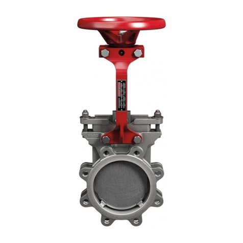
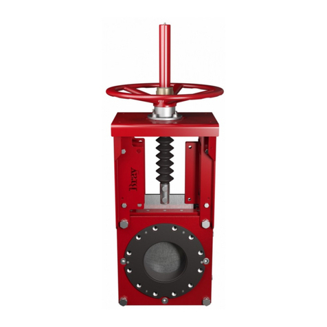
Bray/VAAS O-Ported Series User manual

Bray/VAAS
O-Ported Series Knife Gate Valve
770/780 Series
Operation and Maintenance Manual

Table of Contents
Definition of Terms . . . . . . . . . . . . . . . . . . . . . . . . . . . . . . . . . . 1
Safety Instructions. . . . . . . . . . . . . . . . . . . . . . . . . . . . . . . . . . . 1
Introduction. . . . . . . . . . . . . . . . . . . . . . . . . . . . . . . . . . . . . . 2
Unpacking . . . . . . . . . . . . . . . . . . . . . . . . . . . . . . . . . . . . . . 2
Storage . . . . . . . . . . . . . . . . . . . . . . . . . . . . . . . . . . . . . . . . 2
Installation . . . . . . . . . . . . . . . . . . . . . . . . . . . . . . . . . . . . . . 2
Commissioning . . . . . . . . . . . . . . . . . . . . . . . . . . . . . . . . . . . . 3
Cylinder-Operated Valves . . . . . . . . . . . . . . . . . . . . . . . . . . . . . 3
Manual Valves . . . . . . . . . . . . . . . . . . . . . . . . . . . . . . . . . . . 3
Maintenance . . . . . . . . . . . . . . . . . . . . . . . . . . . . . . . . . . . . . 4
Lubrication . . . . . . . . . . . . . . . . . . . . . . . . . . . . . . . . . . . . 4
Packing Replacement . . . . . . . . . . . . . . . . . . . . . . . . . . . . . . . 5
Seat Replacement . . . . . . . . . . . . . . . . . . . . . . . . . . . . . . . . . 5
Actuator Maintenance . . . . . . . . . . . . . . . . . . . . . . . . . . . . . . . . 6
Spare Parts . . . . . . . . . . . . . . . . . . . . . . . . . . . . . . . . . . . . 6
Packing Details . . . . . . . . . . . . . . . . . . . . . . . . . . . . . . . . . . . . 7
Troubleshooting. . . . . . . . . . . . . . . . . . . . . . . . . . . . . . . . . . . . 8
For information on this product and other Bray products please visit us at our web page - www.bray.com.
O-Ported Series
Operations and Maintenance Manual

1
O-Ported Series
Operation and Maintenance Manual
Definition of Terms - Safety Instructions
READ AND FOLLOW THESE INSTRUCTIONS
SAVE THESE INSTRUCTIONS
DEFINITION OF TERMS
Indicates a potentially hazardous situation which, if not avoided, could result in death or
serious injury.
Indicates a potentially hazardous situation which, if not avoided, may result in minor or
moderate injury.
NOTICE Used without the safety alert symbol indicates a potential situation which, if not avoided,
may result in an undesirable result or state, including property damage.
HAZARD-FREE USE
This device left the factory in proper condition to be safely installed and operated in a hazard-free manner. The notes and
warnings in this document must be observed by the user if this safe condition is to be maintained and hazard-free opera-
tion of the device assured.
Take all necessary precautions to prevent damage to the valve due to rough handling, impact, or improper storage. Do not
use abrasive compounds to clean the valve, or scrape metal surfaces with any objects.
The control systems in which the valve is installed must have proper safeguards to prevent injury to personnel, or damage to
equipment, should failure of system components occur.
QUALIFIED PERSONNEL
• A qualified person in terms of this document is one who is familiar with the installation, commissioning, and operation
of the device and who has appropriate qualifications, such as:
• Is trained in the operation and maintenance of electrical equipment and systems in accordance with established safety
practices
• Is trained or authorized to energize, de-energize, ground, tag, and lock electrical circuits and equipment in accordance
with established safety practices
• Is trained in the proper use and care of personal protective equipment (PPE) in accordance with established safety
practices
• Is trained in first aid
• In cases where the device is installed in a potentially explosive (hazardous) location – is trained in the commissioning,
operation, and maintenance of equipment in hazardous locations

2
O-Ported Series
Operation and Maintenance Manual
The valve must only be installed, commissioned, operated, and repaired by qualied personnel.
The device generates a large mechanical force during normal operation.
All installation, commissioning, operation, and maintenance must be performed under strict observation of all applicable
codes, standards, and safety regulations.
Observe all applicable safety regulations for valves installed in potentially explosive (hazardous) locations.
INTRODUCTION
The Bray/VAAS Series 770/780 provides repeatable bidirectional shutoff in a rugged, double-piece cast body.
Additional information about Series 770/780 valves – including application data, engineering specifications, and actuator
selection is available from your Bray/VAAS distributor or sales representative.
UNPACKING
Ensure the box is not damaged externally. Remove the valve from the packaging and check for any damage to the valve
and its components during transit.
Valve size and brief material specification of body (markings such as “SS” or “DI”) are marked on the valve body. Stainless
steel nameplate (below) fixed on to the yoke of valve contains most of the relevant information on the valve including Bray/
VAAS work order number and unique serial number of the valve. These details should be quoted for all requirements of
service and spares.
SERIAL NUMBER
SIZE MODEL FLG. DRILL BODY GATE
SEAT PACKING CWP MAX TEMP
STORAGE
Wrap the valve with a polyethylene cover. Cover the ports for pneumatic actuator/accessories with plastic caps. Store
these valves in the same packing indoors and without direct exposure to the environment.
INSTALLATION
• Valves can be mounted with flow in both directions.
• Install the valve between flanges using fasteners & gaskets.
• Bolt holes are always blind tapped and care should be taken not to bottom the bolts while tightening. Refer to GA
Drawing/Technical Bulletin for quantity and size of blind tapped holes on valve chest area. If the correct size bolts are
not available, use studs and nuts for chest area bolts to avoid damage of body.

3
O-Ported Series
Operation and Maintenance Manual
Support should be used for valves size 8” and over when installed in vertical pipe. Failure to do so can result in improper
valve operation and/or valve failure.
COMMISSIONING GUIDELINES
• Gland packing is tightened to hold the specified pressure and tested for no leakage before dispatch. However, this may
require some adjustment at site due to loosening in transit etc.
• Check for gland leakage after the valve is subjected to pressure and if any leak is observed, tighten the gland uniformly
in a cris-cross pattern until the leakage stops.
Wrong electrical supply to accessories will damage the equipment. Do not over tighten the gland nuts as this may cause
excessive friction and premature damage to packing.
Cylinder Operated Valves
1. Connect instrument quality air, preferably through an air filter/regulator of adequate size. The recommended air pres-
sure is 80-120 psi (5-8 bar). Refer to the appropriate bulletin/drawing for port and cylinder size details.
2. Ensure the supply air is free from moisture, dirt, and other foreign particles. Drain the filter regulator before operating
the actuator so that pipe rust and dirt if any in the air line will be removed before actuation.
3. If valves are supplied with electrical accessories like limit switch and solenoid valve, ensure wiring is done as per local
electrical safety codes and regulations. Ensure correct electrical supply is given to electrical accessories for proper func-
tioning and safety of the equipment.
4. Open the valve by energizing the solenoid valve/giving air supply to cylinder and operate the valve 2-3 times.
Manual valves
Open/Close the valve manually and observe valve operation.

4
O-Ported Series
Operation and Maintenance Manual
MAINTENANCE
NOTICE
Any modification or use of unauthorized parts voids any and all warranty considerations.
Lubrication
The manual valve stem should be lubricated at regular intervals for smooth operation of the valve. A lubrication nipple is
provided on the collar. Cylinder operated valves do not require routine lubrication.
NOTICE
If the cylinder actuator is disassembled for repair, the cylinder wall and seals need to be lubricated with a lithium-based
grease prior to reassembly.
Manual Valve Stem Cylinder Actuator

5
O-Ported Series
Operation and Maintenance Manual
Packing Replacement
Relieve line pressure before loosening gland nuts to avoid injury and/or equipment damage.
1. Relieve the line pressure.
2. Fully close the valve.
3. Ensure the line is empty, and flush if necessary.
Manual Valves
1. Ensure the valve is fully closed .
2. Disconnect the stem from the gate by removing the clevis bolts & nuts (6).
3. Rotate the handwheel (1) counter-clockwise by holding the stem from rotation, so that
the stem retracts fully from the gate.
4. If valves are supplied with bellows, ensure stem is not rotating, as rotation will damage
the bellows.
5. Remove the gland nuts (2) and the gland (3).
6. Remove the old packing (4) from the packing
chamber, one layer at a time, using a long thin
tool to pry it out.
7. Insert the new packing one at a time according
to the illustration below. Stagger the cut end
of the packing so that they meet together and
do not line up.
8. Install the packing gland (3) and gland nuts (2).
9. Ensure the gap between the gland and the gate is uniform all around
10. Tighten the gland nuts finger tight plus one turn.
11. For Series780, remove the gate cover at the bottom side and repeat the procedure as
mentioned above for bottom packing replacements.
12. Lower the stem by rotating the handwheel clockwise while holding the stem and fasten
the stem to the gate with nuts & bolts
NOTICE
If leakage is observed from the packing area after installing the valve in the pipeline and the valve is pressurized or charged with
media, tighten the gland nuts evenly side to side just enough to stop leakage. Do not over-tighten the gland nuts.
Seat Replacement
1. Relieve the line pressure and close the valve. Flush the line if necessary.
2. Remove the valve from the line by loosening the flange mounting bolts, studs, and nuts.
3. Clamp the valve in the vertical position to a fixture. Do not block the valve port when clamping the valve. An overhead
Quad Seal
2” - 16”
“C” Packing PTFE
18” and up
3 Layer Packing
4 Layer Packing
Packing Joint Angle 45°
1
4
2
3
5
6

6
O-Ported Series
Operation and Maintenance Manual
hoist may be needed for larger size valves.
4. Make sure the valve is in the open position.
5. Replacing the seats does not require valve or actuator disassembly.
6. Remove the seats on either side (which are drop-in fitted) and replace with new seats.
7. Ensure alignment of the internal seat bores with same level
8. Seats require lubrication before installing. A silicon-based lubricant is recommended. (Applicable for Series 770)
ACTUATOR MAINTENANCE
Pneumatic Cylinder
The Bray/VAAS pneumatic cylinder actuator is a low maintenance design and does not require routine maintenance. It has
an FRP tube which is lubricated for life with a special coating on the inside wall. Filtered dry, instrument quality air (non-
lubricated) should be used for its operation at the specified air supply pressure.
Recommended spare parts
Following are parts recommended as spares, which may be stocked. Following are general recommended spares for valves.
Provide the valve serial number and work order number from the nameplate for proper parts.
• Gland packing
• Spare Seat
• Cylinder repair kit

7
O-Ported Series
Operation and Maintenance Manual
Packing Details
Series 770
Valve Size (in.) Packing Size (mm) Length (mm) Packing Layers Quad Seal Layer Total Layers
2 Sq. 8 235 2 1 3
3 Sq. 8 275 2 1 3
4 Sq. 8 400 2 1 3
5 Sq. 8 425 2 1 3
6 Sq. 8 475 2 1 3
8 Sq. 8 545 2 1 3
10 Sq. 8 650 2 1 3
12 Sq. 8 775 3 1 4
14 Sq. 10 925 3 1 4
16 Sq. 10 1000 3 1 4
18 Sq. 10 1100 3 1 4
20 Sq. 16 1250 2 1 3
24 Sq. 16 1440 2 1 3
Series 780
Valve Size (in.) Packing Size (mm) Length (mm) Total Layers
2 Sq. 8 270 6
3 Sq. 10 330 6
4 Sq. 10 395 6
5 Sq. 10 425 6
6 Sq. 10 480 6
8 Sq. 10 580 6
10 Sq. 10 675 6
12 Sq. 12.7 800 6
14 Sq. 12.7 975 6
16 Sq. 16 1150 6
18 Sq. 16 1300 8
20 Sq. 16 1375 8
24 Sq. 16 1575 8

8
O-Ported Series
Operation and Maintenance Manual
Troubleshooting
Trouble Possible cause Solution
Media oozing out of gland packing Packing deteriorated Replace packing
In fully closed position, valve leaks
Seat is worn out or torn Replace seat
Gate is scratched Replace gate
High torque during valve seating and
unseating
Misalignment between gate and stem
a) Remove the clevis fasteners
b) Loosen the superstructure fasteners
c) Adjust the alignment of the stem and
gate
d) Connect the clevis fasteners
e) Retighten superstructure fasteners
Packing is not tighten properly Adjust gland nuts
Valve jerks during open and close
Superstructure fasteners loosen Tighten the super structure fasteners
Insufficient air supply Pneumatic operated valves: Increase supply
pressure
Solenoid valve dust accumulation Remove and clean solenoid valve
Piston rod seal damaged Replace seal
All statements, technical information, and recommendations
in this bulletin are for general use only. Consult Bray/VAAS
representatives or factory for the specific requirements and
material selection for your intended application. The right to
change or modify product design or product without prior notice
is reserved. Patents issued and applied for worldwide.
Bray®is a registered trademark of
Bray International, Inc.
© 2015 Bray International, Inc. All rights reserved.
OM_O-Ported Series_12_20_2016
Bray/VAAS
Division of Bray International, Inc.
13333 Westland East Blvd.
Houston, Texas 77041
Tel: 281.894.5454 • www.bray.com
This manual suits for next models
2
Table of contents
Other Bray/VAAS Control Unit manuals
Popular Control Unit manuals by other brands

Lamtec
Lamtec BT300 BurnerTronic quick reference
STATUS SCIENTIFIC CONTROLS
STATUS SCIENTIFIC CONTROLS MCU3 Installation and Hardware Configuration Manual
Carlisle
Carlisle Ransburg CCV-5100 Service manual
Cooper
Cooper S280-79-10 Install and operation instructions
Franke
Franke ZAQUA030 Installation and operating instructions
hager
hager h3 h400 User instructions
