BRB Systems USA TX-101 User manual

1
BRB Systems USA Co.
Instruction Manual
Wireless Voice Release Counter
IMPORTANT: Read and understand this manual before assembling, installing or
using this system. Improper use of this system can cause serious injury.
Table Of Contents
(1) Safety Information…………………………………………………………………………….
(2) Installation…………………………………………………………………………………………
(3) Set Up…………………..…………………………………………………………………………..
(4) Operation………………………………………………………………………………………….
(5) Counter Codes………………………………………………………………………………………..
(6) Maintenance……………………………………………………………………………………………..
(7) Warranty………………………………………………………………………………………………
2
3
3
6
9
10
11

2
(1) Safety Information
Make certain that any person assembling or installing this system has read and fully
understood this Instruction Manual. It is your guide to safe and proper operation of this
system.
Counter units are to be used with 12V dc power sources only. The 12V dc power
sources that may be used are; 12V lead acid batteries or 12V regulated ac to dc
power supplies.
12V lead acid batteries (such as car type batteries) contain acid and so extreme
care must be taken when handing them.
12V car batteries are capable of supplying large amounts of current and care must
be taken not to connect the + (red) and –(black) terminals together.
Protect the power cord from being walked on, pinched or damaged in any way.
Disconnect this apparatus from its power source during lightning storms or when
unused for extended periods of time.
Use only the attachment parts/accessories supplied by BRB Systems USA Co.
Do not allow liquid entry into the system components.
Ensure that the traps are disconnected from their power sources and unloaded
before connection of a Counter unit. Failure to do so could result in the
unexpected operation of the trap causing serious injury.
CAUTION:
This system is powered by electricity. To reduce the risk of electric shock, do
not remove any cover from the apparatus. There are no user serviceable parts
inside. Refer servicing to BRB Systems USA Co.

3
(2) Installation
Installation of the Counter should be to the side or rear of the shooting position, in such
a place as not to obstruct or distract the shooter. The counter unit should be mounted
either to a post, wall or tree and must be mounted vertically without obstruction
between its antenna, any component of the voice release system and the trap house.
Counter Unit Connections
Battery Power
10ft 2 core cable = Counter power. Connect to 12V battery.
Power +12V = Red.
Power -12V = Black.
(3) Set Up
Use this equipment to control target use with BRB Wireless Trap, Wireless Skeet or
Wireless Overlay Voice Release Systems.
This equipment has been designed for user versatility, which is achieved by
offering a number of set up options. Unless specified otherwise when ordered,
each piece of this equipment will be preset to factory settings before shipping.
For many customers no changes will be necessary. Should you need to make
any changes from the factory settings a comprehensive description of how to
do so follows.
Each Counter Unit can be set by the club/owner into one of the following modes:
No-load target counting - individual targets
Preload target counting - rounds of 25 targets
Free play
No-load target counting requires a Dongle to be in the Counter Unit at the time of
shooting and charges the Dongle per shot. This counter mode is commonly used by a
single shooter in the Sporting disciplines.
Preload target counting allows shooters to each load multiples of 25 targets onto a
Counter Unit, where they are stored until used. Targets are preloaded by inserting and
then removing a Dongle. This counter mode is commonly used by single or multiple
shooters, in the Trap or Skeet disciplines.

4
Free play mode allows the counter equipment to be used as a release system without
any need for a Dongle to be inserted for payment.
Once a Counter Unit has been set to No-load Counting, Preload Counting, or Free Play it
will stay in that mode even if powered off. If in the future the Counter Unit is required
to work in a different count mode it can be reset using the following procedures.
Setting a Counter Unit for No-load Target Counting
Power on the Counter Unit.
Insert No-load Programming Dongle into the socket.
The display shows Cntr then changes to donE.
Remove the No-load Programming Dongle.
Setting a Counter Unit for Pre-load Target Counting
Power on the Counter Unit.
Insert Pre-load Programming Dongle into the socket.
The display shows PreL then changes to donE.
Remove the Pre-load Programming Dongle.
Setting a Counter Unit for Free Play
Power on the Counter Unit.
Insert a Free Play Programming Dongle into the socket.
The display shows FrEE then changes to donE.
Remove the Free Play Programming Dongle.
Any Dongle can be made into a No-load Programming Dongle, Preload
Programming Dongle or Free Play Programming Dongle as described in the
Console Instruction Manual.

5
Counter Unit Dipswitch Settings
The counter unit identity is set with dipswitches. To access the dip switches carefully
remove the cover without pulling the internal wiring that links between the cover and
the enclosure body.
Switch numbers are printed on the body of the dipswitch.
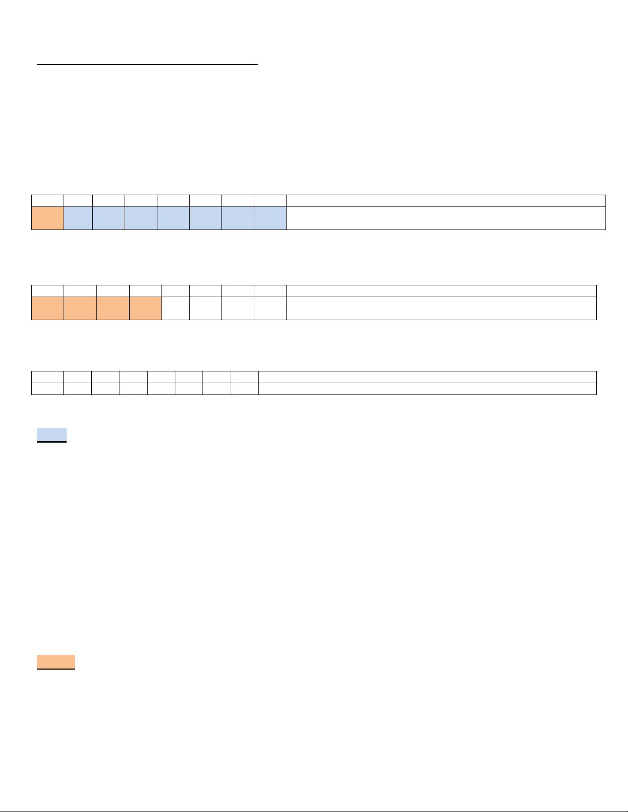
TOP
1
2
3
4
5
6
7
8
CODE
CHN
CHN
CHN
CHN
CHN
CHN
CHN
The 7 CHN switches must match between TX,RX, VB and Counter –Used to set RF
frequency
MIDDLE
1
2
3
4
5
6
7
8
CODE
CODE
CODE
CODE
OFF
OFF
OFF
OFF
The 5 CODE switches must match between TX, RX, VB and Counter –Used to
set signal encoding
BOTTOM
1
2
3
4
5
6
7
8
OFF
OFF
OFF
OFF
OFF
OFF
OFF
OFF
UNUSED –Set all OFF
CHN Channel Dipswitches
The seven CHN dipswitches (#2-8 of the TOP dipswitch) set the frequency of the
equipment radio communication and have 128 possible frequency variations. Using a
unique CHN setting, for one set of Counter Unit, Button Controller, Receiver and Voice
Box, eliminates cross calls between adjacent fields, because each field has a different
working frequency.
The seven CHN dipswitch settings on the Counter Unit, Button Controller, Receiver and
Voice Box must match for the system to operate.
These will be preset when the unit is shipped and so under most circumstances should
not need you to change them.
CODE Signal Encoding Dipswitches
The five CODE switches (#1 on the TOP dipswitch and switches #1-4 on the MIDDLE
dipswitch) set the encoding, do not affect the transmission frequency and expand the
possible number of individual identities to 4096.

6
The CODE dipswitch settings on the Counter Unit, Button Controller, Receiver and Voice
Box must match for the system to operate.
These will be preset when the unit is shipped. Unless you need more than the 128
different transmitter identities available with the CHN dipswitches it should not be
necessary to change the CODE dipswitches.
(4) Operation
BRB Wireless Trap, Skeet and Overlay Voice Release Systems can be used with or
without counting. Changing between modes is made with the dipswitches in the Button
Controller.
Non-counter operation = switches 1-4 on the TOP Button Controller dipswitch
must be the same as switches 1-4 on the LOWER dipswitch.
With counter operation = at least one of the switches, 1-4 on the TOP Button
Controller dipswitch, must be different from switches 1-4 on the LOWER dipswitch.
Therefore changing between non-counter operation and with counter operation is done
by simply switching one of the switches (#1-4) of the LOWER dipswitch.
When a counter/ non-counter switch has been changed, press ‘MIC OFF’ followed by
‘MIC ON’to install the new mode.
Note: Because this makes changing operation very easy, it is important that how these
changes are made does not become known to the shooter.
(4.1)Counter Unit Operation
With No-load or Preload counting, a shooter Dongle must be inserted into the counter
unit to control payment before a target can be released. A shooter Dongle can be either
count up or count down. Count Up and Count Down Dongles are created by the club
using the Console. Instructions on how to create Dongles are found in the Console
Instruction Manual.

7
(4.1.1) No-load Target Counting
Dongles
To release a target using a Counter Unit set to No-load Counting, a Dongle must be
inserted into the Counter Unit socket and left inserted for as long as the shooter requires
targets to be released. If the Dongle is set to Count Up mode, then the shooter may
release 10,000 individual targets before the Dongle will need to be reset. If the Dongle
is set to Count Down mode then then the club must preprogram the required number of
individual targets into the Dongle using the Console. Any amount between 0 and 999
can be programmed.
Once the Dongle has been inserted and the Counter Unit is powered on, the unit will
stay powered for 30 minutes after use has stopped. Once the Dongle has been removed
the display will read IdlE and wait for another Dongle for 10 seconds. If none is
inserted after 10 seconds the Counter Unit will power off.
Count/Credit –Counting Up
With a Counter Unit powered on and a Count Up Dongle inserted, the display will show
the number of targets that Dongle has released. The count of a Count Up Dongle will
read between 0 and 10,000 and will be displayed as follows:
1234 1234
The Dongle has recorded the release of 1234 targets.
When a Dongle has released 9999 targets no more targets will be released and an
audible ‘Beep; will sound. To release more targets using this Dongle the count must
first be cleared using the Console.
Count Credit - Counting Down
With a counter powered on and a Count Down Dongle inserted, the display will show the
amount of target credit available. The credit remaining on a Count Down Dongle will be
displayed as follows:
fvdg .9.8.7
The Dongle has a credit remaining of 987 targets.
When the count reaches zero no more targets can be released until more count is added
to the Dongle using the Console.
If a user attempts to release a target with zero credit on a Dongle, or release a pair in
Count Down mode with a credit of only 1 available, the user will hear an audible ‘beep’
to inform them that no credit exists.

8
(4.1.2) Preload Target Counting
Dongles
To release a target using a Counter set to Preload Counting mode, a Counter Unit must
have stored credit of at least 1. Credit is added to the Counter by inserting a Count Up
or Count Down Dongle that is has at least 25 targets available.
When a Preload Counter is powered on, the display will show the count credit that is
already stored in it. This figure will be between 0 and 999.
When a Dongle is inserted into the Counter, the Counter will take 25 targets from the
Dongle and the previous credit shown on the display will rapidly increase by 25 targets.
If the Counter has been set by the club/owner to give extra targets for each round of 25,
to allow for broken targets, these will also be added to the Counter credit.
Once the Dongle has been inserted and the unit is powered on, the unit will stay
powered for 30 minutes after use has stopped.
If a Dongle is inserted that does not have enough credit to allow 25 targets to be taken
from it, the display will flash the amount of credit available on the Dongle to make the
shooter aware that the credit is insufficient. When the Dongle is removed the display
will return to showing the Counter stored credit.
Count/Credit
With a Counter powered on the display will show the amount of target credit already
stored on the unit. A Preload counter display always displays and releases targets by
counting down.
234 .2.3.4
The Counter Unit has a 234 target credit. When the count reaches zero no more targets
can be released until more count is added to the counter using a Dongle.
When a Count Up Dongle is used to credit the Counter, 25 targets will be added the
count already stored on the Dongle.
When a Count Down Dongle is used to credit the Counter, 25 targets will be subtracted
from the count credit stored on the Dongle.
When either a Count Up or Count Down Dongle is removed, the target credits remain
stored in the Counter Unit. If more credit needs to be added, reinsert the Dongle.
Other shooters can add credit by inserting their Dongles.

9
If a shooter attempts to release a target with zero credit on the Counter Unit, or release
a pair of targets with only 1 credit available, an audible ‘beep’ will sound to inform the
shooter that no credit exists and no target will be released.
Erasing Unused Targets
Any unused target credit stored on the counter can be removed by inserting a Preload
Programming Dongle into the Counter Unit. The display will show PreL done then
the display will show zero credit.
(4.1.3) Free Play
Dongles
To release a target, using a Counter unit set to Free Play mode, it is not necessary to
insert any Dongle. If a dongle is inserted into the counter the display will flash FrEE to
alert the shooter, until the Dongle is removed.
Count/Credit
When a Counter Unit set to Free Play mode is powered on the display will read FrEE and
any target combination can be released.
(4.14) All Counter Modes
Ground ID
If a Dongle with the wrong Ground ID is inserted, no target can be released. The
Counter Unit display will show FaiL Err3 will be until the Dongle is removed.
(5) Counter Codes
If the Counter Unit sees a Dongle with the incorrect ground ID or cannot read a Dongle
the display will show an error message until the Dongle is removed.
‘Err 3’ = Bad ground ID. Dongle is from another ground.
‘Err 5’ = Cannot read Dongle.

10
(6) Maintenance
The rugged manufacturing of this Wireless Voice Release Counter should ensure many
years of trouble free use if it is not abused and given simple maintenance.
Do not allow any component to be immersed in water.
Do not leave the equipment outside, in the weather, for indefinite periods of time.
Store in a cool dry place.
Regularly inspect the equipment for wear or damage. If any wear or damage is
found seek service from BRB Systems USA Co.
Should difficulty be found with the system operation, do not dismantle any part of the
system. This will void the warranty and may result in an electric shock or fire.
Refer servicing to BRB Systems USA Co.

11
(7) BRB Systems USA Co. - Limited Warranty
This BRB Systems USA Co. product, supplied in the original packaging to the original purchaser, is warranted by BRB Systems USA Co.
against manufacturing defects in materials and workmanship for a limited warranty period of:
One (1) Year Parts and Labor.
This limited warranty begins on the original date of purchase and is valid only on products purchased and used in the USA.
This warranty will terminate automatically prior to its stated expiration if the original purchaser sells or transfers the product to any
other party.
BRB Systems USA Co. will repair or replace this product, at our option and at no charge as stipulated herein, with new or
reconditioned parts or products if found to be defective during the limited warranty period specified above.
All replaced parts and products become the property of BRB Systems USA Co. and must be returned to BRB Systems USA Co.
Replacement parts and products assume the remaining original warranty or ninety (90) days, whichever is longer.
This limited warranty covers defects in materials and workmanship encountered in normal use of this product and shall not apply to
defects or injuries caused by the following, including, but not limited to: damage which occurs in shipment; delivery and installation;
applications and uses for which this product was not intended; product alterations not authorized by BRB Systems USA Co.; cosmetic
damage or exterior finish; accidents; neglect; fire; water damage; vermin or insect infestation; lightning or other acts of nature; use
of products, equipment systems, utilities, services, supplies, accessories, applications, installations, repairs, external wiring or
connectors not supplied or authorized by BRB Systems USA Co. which damage this product or result in service problems; incorrect
electrical line voltage; fluctuations and surges; customer adjustments and failure to follow operating instructions, cleaning,
maintenance and environmental instructions that are covered and prescribed in the Instruction Manual.
BRB Systems USA Co. does not warrant uninterrupted or error-free operation of the product.
BRB Systems USA Co. shall not be liable for loss of revenue or profits, failure to realize savings or other benefits, or any other special,
incidental or consequential damages caused by the use, misuse or inability to use this product, regardless of the legal theory on
which the claim is based, even if BRB Systems USA Co. has been advised of the possibility of such damages. Nor shall recovery of any
kind against BRB Systems USA Co. be greater in amount than the purchase price of the product sold by BRB Systems USA Co.
Without limiting the foregoing, the purchaser assumes all risk and liability for loss, damage or injury to purchaser and purchaser’s
property and to others and their property arising out of the use, misuse or inability to use this product sold by BRB Systems USA Co.
not caused directly by the negligence of BRB Systems USA Co.
To receive warranty service contact BRB Systems USA Co. for problem determination and service procedure. If it is
determined that the product requires warranty service, ship the product, in its original packaging or its equivalent,
together with proof of purchase, prepaid insured to BRB Systems USA Co.
Products repaired or replaced under warranty will be returned to you, within a reasonable time, freight prepaid.
To obtain warranty service contact BRB Systems USA Co. at:
brbsystemsusa@yahoo.com or call: 412 773-2128.
V1.02
Other manuals for TX-101
2
Table of contents