Bredenoord R0292 User manual
© Bredenoord bv 2016
Operation manual
|www.bredenoord.com
Bredenoord bv R ent al - Postbus 20122 - 7302 HC Apeldoorn - Zutphensestraat 319 - 7325 WT Apeldoorn
Tel. +31(0)55 301 85 40 - Fax +31(0)55 301 85 50 - www.bredenoord.com - rental@bredenoord.com
10/31/2016
Power light tower
R0292 - R0306
Bredenoord Aggregaten B.V.
Zutpensestraat 319
7325 WT APELDOORN
Tel: 055-3018501
Fax: 055-3018500
E-mail: info@bredenoord.com
Internet: www.bredenoord.com

Volledige bedieningshandleiding A
© Bredenoord bv 2016
2
Table of content
1................................................................................................................................... 3
Complete operation manual
2................................................................................................................................... 4
Safety measures and symbols
................................................................................................................................... 42.1 Safety markings in the text
................................................................................................................................... 42.2 Safety instructions
................................................................................................................................... 42.3 Safety symbols on the genset
3................................................................................................................................... 6
Installation PLM
4................................................................................................................................... 7
Fuel supply
5................................................................................................................................... 8
Bleeding
6................................................................................................................................... 9
Starting and stopping generator
................................................................................................................................... 96.1 Manual start and stop
................................................................................................................................... 106.2 Starting with timer
................................................................................................................................... 116.3 Starting with lightsensor
7................................................................................................................................... 13
Components
8................................................................................................................................... 14
Moving the PLM
9................................................................................................................................... 15
Expiring of the warranty
10 ................................................................................................................................... 16
Appendix: Timer

Volledige bedieningshandleiding A
© Bredenoord bv 2016
3
1Complete operation manual
Power light tower
R0292 - R0306
Volledige bedieningshandleiding A
© Bredenoord bv 2016
4
2Safety measures and symbols
Every other use of the Fixed Light Tower than that described in this user manual, can lead to a dangerous
work ing situation, both for the Fixed Light Tower and user(s). Bredenoord bv refuses to accept responsibility for
any claim of damage or human harm which has occurred because of not following the instructions in this
manual or by lack of care during use, installation, service, maintenance or repair of the Fixed Light Tower. It is
necessary, before usage, to read this user manual with care. Always follow the safety instructions! For
information regarding installation, maintenance or repair not included in this manual, please contact Bredenoord
bv.
2.1 Safety markings in the text
The safety markings in the text have the following meaning:
BEWARE!
If a comment has additional information, it’s drawing your attention to possible problems or dangers.
WARNING!
Indicates that you can (seriously) injure yourself if you do not carry out the procedures with care.
DANGER!
Indicates that your life is directly threatened if you do not carry out the procedures with care.
2.2 Safety instructions
·Only start the machine when all safety measures have been observed.
·The Power Light Tower is only permitted to be operated, serviced, maintained and connected by qualified
and adequately trained personnel that is authorized by the customer.
·No maintenance, connection, commissioning, usage or other operation before consulting the manual.
·Switch the genset safe before carrying out maintenance, repairs or other jobs.
·Operate the generator only when all protective parts have been correctly installed (again).
·Watch out for parts that are under voltage in the electric switchboard cabinets.
·Watch out for possible hot part.
·Avoid contact between body parts, hair, jewellery or clothes and rotating parts, for example the cooling fan
or the v-belts, otherwise you could become trapped or injured.
·Keep the doors of the room and/or genset closed during operation because of cooling, noise and entry.
·Keep open fires and other combustible elements away from the Power Light Tower. Also don´t install the
genset nearby flammable gasses.
·Keep a powder fire extinguisher in the direct proximity of the Power Light Tower.
·Avoid contact of diesel oil, grease or battery acid with electrical cables.
·Be careful with batteries, very high currents will run when short-circuited. Batteries sometimes also contain
corrosive acid.
·Apply appropriate (personal) safety measures when servicing the Power Light Tower.
·Do not use the genset if your concentration is diminished for example by tiredness or alcohol
consumption.
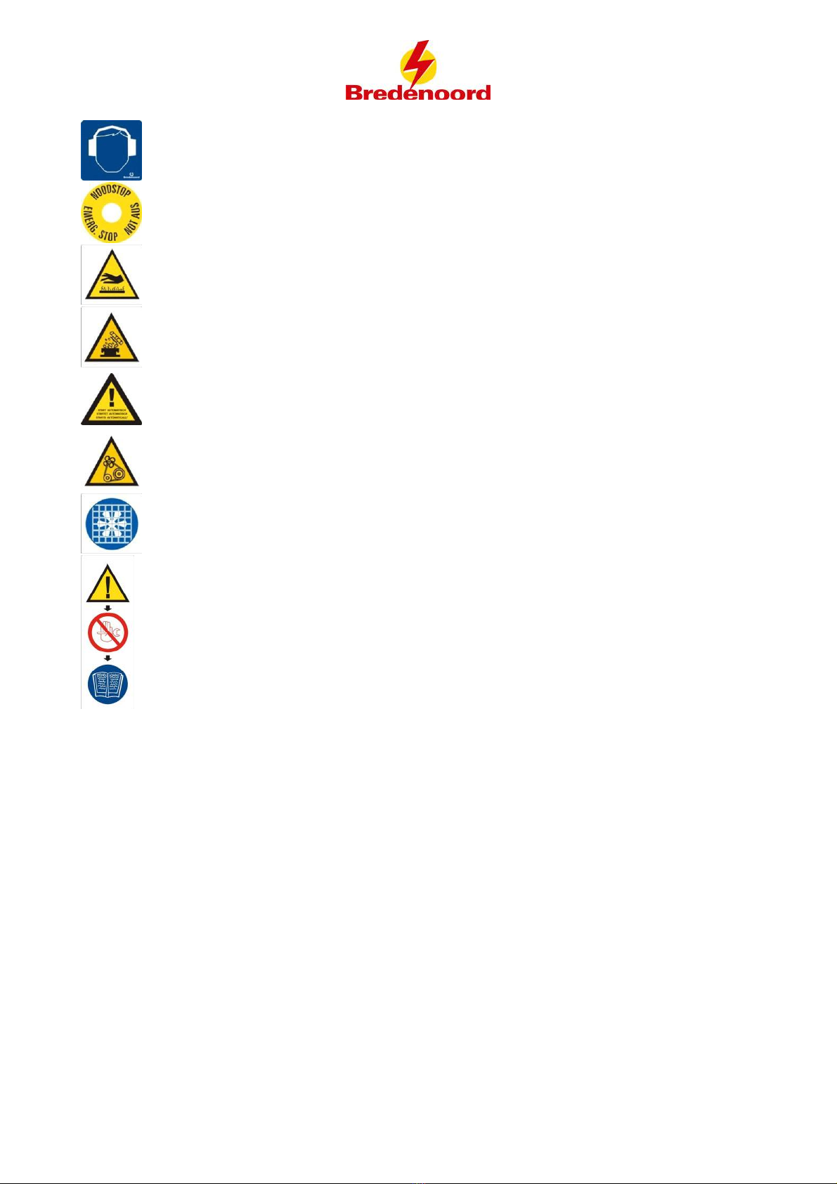
2.3 Safety symbols on the genset
Warning stickers have been placed on places where protection is not practical. To warn for dangerous
situations the following safety symbols can be used on the genset:
Danger! You are close to a life-threatening voltage!
Volledige bedieningshandleiding A
© Bredenoord bv 2016
5
Ear protection required!
Emergency stop!
Danger of burns! Hot parts
Danger of burns! Hot liquid
Beware! This machine can start automatically!
Danger of entrapment! Rotating parts
Beware: ventilator
This sticker refers to this manual:
BEWARE!
It is not permitted to make adjustments in the control panel other than by a qualified electrician. In
all other cases only allow the installation to be adjusted by an employee of Bredenoord. When you
make adjustments yourself or have adjustments made, the firm Bredenoord is not in any way
responsible for possible damage as a result of incorrect installation of the genset.
Volledige bedieningshandleiding A
© Bredenoord bv 2016
6
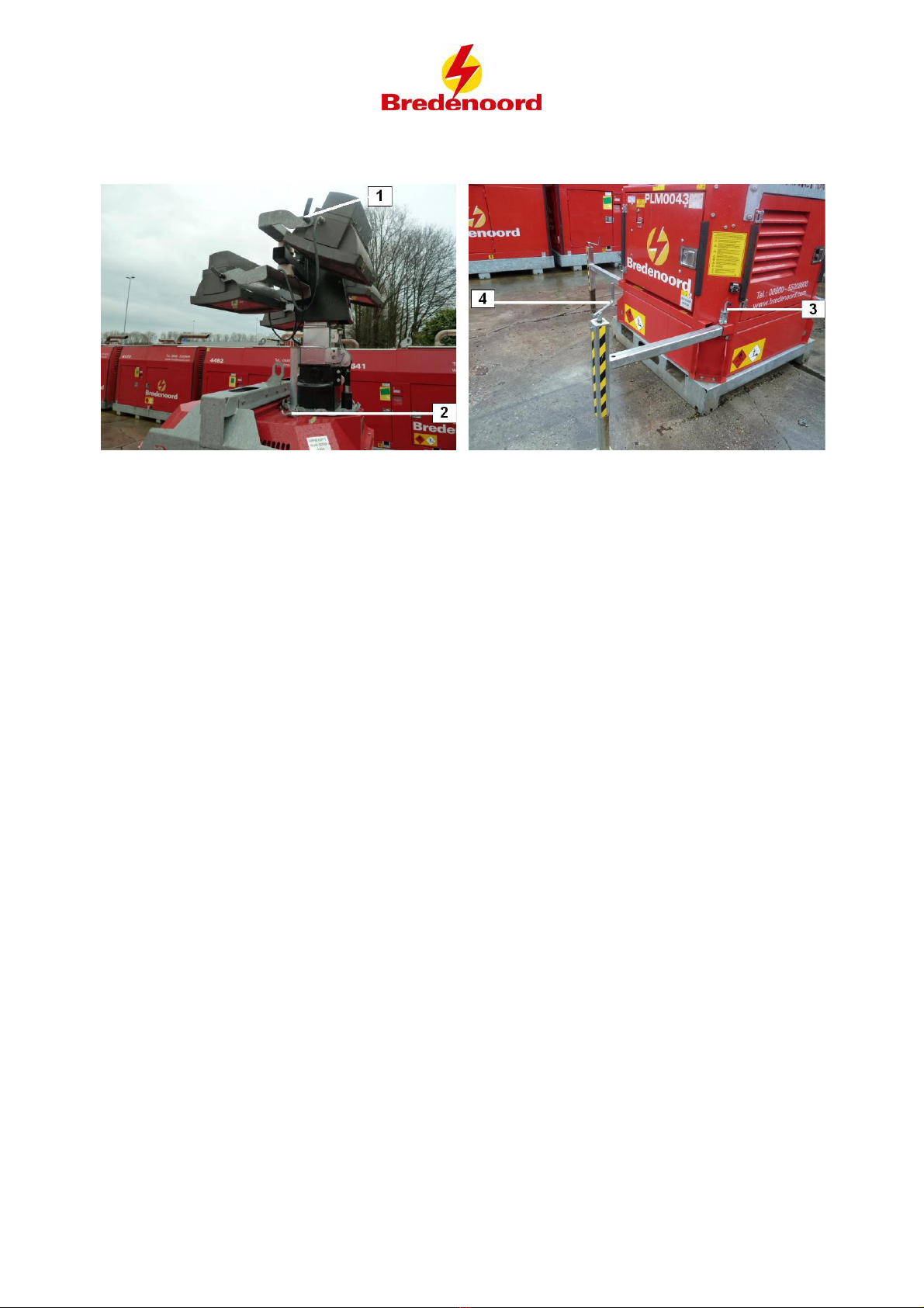
3Installation PLM
·Place the light tower on a flat surface, it should not tilt more than 10°. Check if the surface is strong enough.
·Tilt and/or turn the lights in the desired position and tighten the lights with the lever (1).
·Pull the blocking pin (2) loose to twist the light tower. Turn the light tower in the desired position. Lock the
tower again with the blocking pin (2).
·Pull the pin (3) up and pull the stabilizer till pen (3) falls into it's corresponding hole.
·Drop the stabilizer by turning the lever (4) and level the Light tower horizontal
·Ground the Light Tower with the earth stud on the outside of the housing.

Volledige bedieningshandleiding A
© Bredenoord bv 2016
7
4Fuel supply
This generator only uses the internal fuel tank.
Volledige bedieningshandleiding A
© Bredenoord bv 2016
8
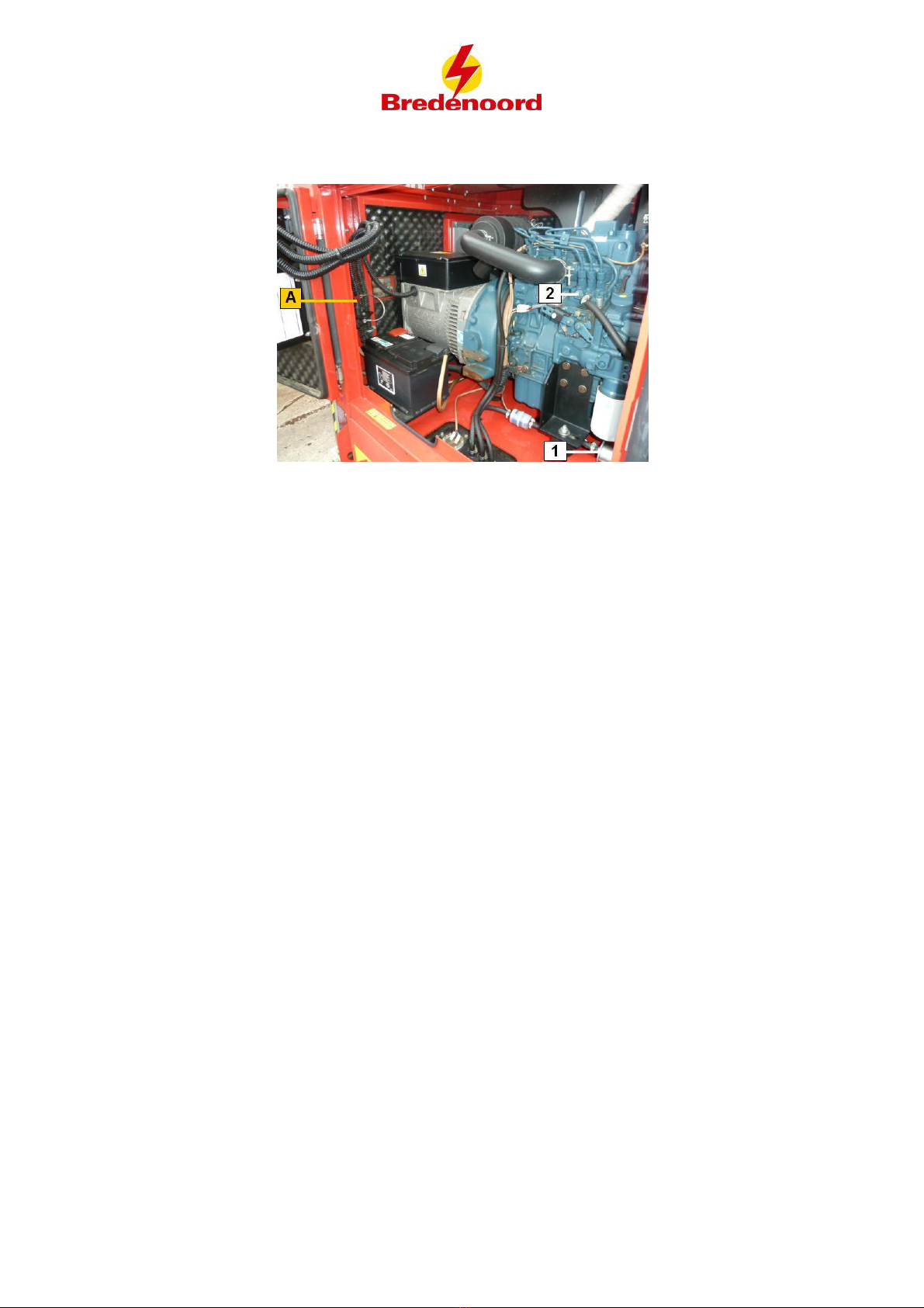
5 Bleeding
·Activate the battery switch(A).
·Open the bleedingnipple (2) and be prepared to close it again.
·Press "START" on the MP nano.
·The fuelpomp(1) pumps while its glowing.
·Close the bleedingnipple (2) when only oil flows out of the nipple.
Volledige bedieningshandleiding A
© Bredenoord bv 2016
9
6Starting and stopping generator
The generator could be started manually or automatically with a timer / lightsensor.
6.1 Manual start and stop
Start generator and lights on.
·Switch the battery switch on (A).
·Turn the selector switch(2) to "MANUAL"
·Press "START" on the MP nano.
·The generator starts.
·The light tower can be raised with the lever(6). A red line on the tower indicates that the
maximum height has been reached.
·The lights can be activated with their corresponding circuit breakers.(4)
Lights off and stopping generator.
·Switch the lights of with the circuit breakers. (4)
·Bring the tower down with the lever. (6)
·The generator stops.
·Turn the selector switch (2) to "OFF".
·Turn off the battery switch (A).
Volledige bedieningshandleiding A
© Bredenoord bv 2016
10
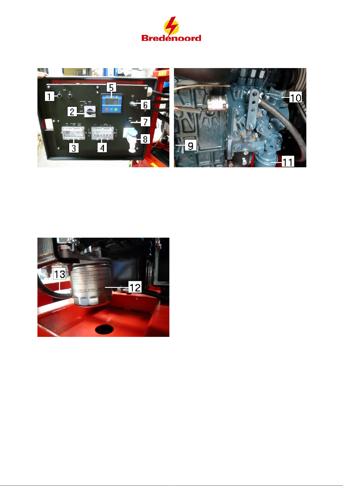
6.2 Starting with timer
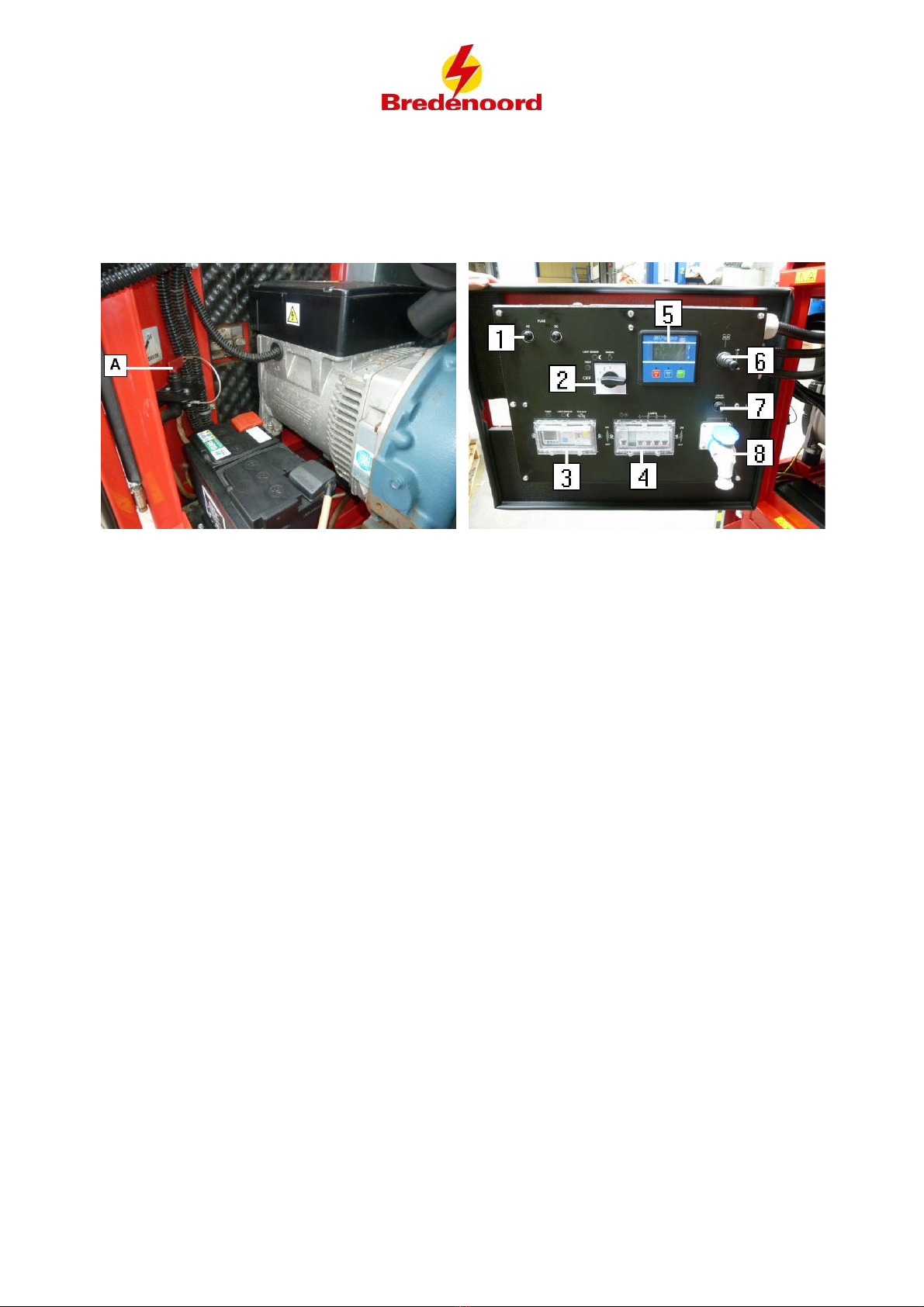
1. AC en DC
fuses
2. Operator
selector switch
3. Timer,
sensor en
main circuit
breaker
4. Fuse tower
and lights
5. MPnano Plus controller
6. Tower stick controller
7. Circuit breaker
8. Connection load
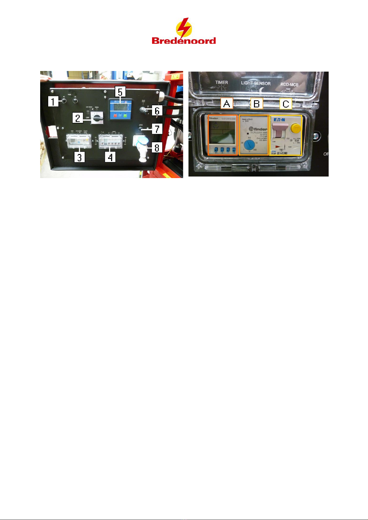
The upper picture relates to 3. Timer, sensor
en main circuit breaker.
A: This device is used to program the timer
which will activate or deactivate the lights.
B: This device is used to detect whether it is
dark, so that the lights can go on.
C: This is the main circuit breaker for the
whole system
Firstly set up the tower on the right height with the lever before setting the generator
with the timer
The generator has to be activated to be able to operate the tower. Start the generator manually if
necessary.
Starting with timer
Read the manual of the Timer before proceeding. That manual will explain how the timer works.
The manual can be found in the appendix.
·Activate the battery switch.
·Move the operator selector switch into "TIMER".
·Slide the Main Circuit Breaker up. The system is ON.
·Press the AUTO button on the MP nano plus (5). A green LED will light up above the button.
This indicates that its on automatic operating mode.
·Turn on the lights with the fuses (4).
·Program the timer so that the PLM switches on and off at a programmed time.
·The generator is ready to start automatically and will start on the programmed time of the timer
(3A).
Stopping with timer
·The generator stops automatically at a programmed time of the timer (3A). The generator will
go into standby when it stops and will start again on it's programmed time.
Shutdown the generator completely
·Turn off the lights with their corresponding fuses(4).
Volledige bedieningshandleiding A
© Bredenoord bv 2016
11
·Be advised to bring the tower down first with the Tower stick controller(6) ( The generator has
to run, start up manually if necessary)
·Turn the operator selector switch (2) to "OFF"
·Turn off the battery switch (1).
6.3 Starting with lightsensor
1. AC en DC
fuses
2. Operator
selector switch
3. Timer,
sensor en
main circuit
breaker
4. Fuse tower
and lights
5. MPnano Plus controller
6. Tower stick controller
7. Circuit breaker
8. Connection load
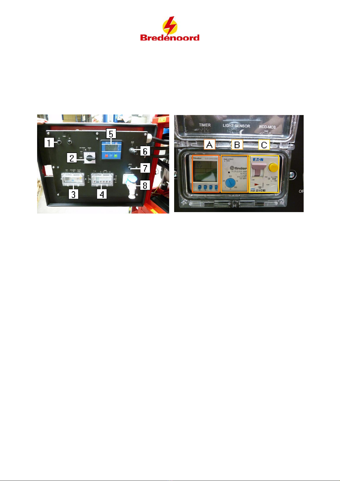
The upper picture relates to 3. Timer, sensor
en main circuit breaker.
A: This device is used to program the timer
which will activate or deactivate the lights.
B: This device is used to detect whether it is
dark, so that the lights can go on.
C: This is the main circuit breaker for the
whole system
Firstly set up the tower on the right height with the lever before setting the generator
with the light sensor.
The generator has to be activated to be able to operate the tower. Start the generator manually if
necessary.
Starting with lightsensor
·Turn battery switch on.
·Move the operator selector switch( 2) into "Light sensor"
·Slide the Main circuit breaker (3) up. The system is now ON.
·Press AUTO on the MPnano plus (5). A green LED will shine above the button. This indicates
that the operator mode is on automatic.
·Turn on the lights with the fuses (4).
·The generator will stand on standby to start automatically. It will start when de lightsensor
detects when its dark and will go off when it is light again.
Stopping with lightsensor
·The generator stops automatically at a programmed time of the timer (3A). The generator will
go into standby when it stops and will start again on it's programmed time.

Volledige bedieningshandleiding A
© Bredenoord bv 2016
12
Shutdown generator completely
·Turn off the lights with their corresponding fuses (4)
·Be advised to bring the tower down first with the Tower stick controller (6) ( The generator has
to run, start up manually if necessary)
·Turn the operator selector switch (2) to "OFF"
·Turn off the battery switch (1).
Volledige bedieningshandleiding A
© Bredenoord bv 2016
13
7 Components
1. AC & DC fuses
2. Operator selector switch
3. Timer, Light sensor and Main circuit breaker
4. Fuses Lights and tower
5. MP nano
6. Hydraulic pump for tower up/down
7. Circuit breaker
8. Connection load
9. Oil level
10. Oil filling point
11. Oil filter
12. Fuel filter
13. Fuel fillingpoint
14. Oil drain pump
Volledige bedieningshandleiding A
© Bredenoord bv 2016
14
8Moving the PLM
Mobile products of Bredenoord are often moved and are therefore usually equipped with a lifting eye and forklift
beams. Check before moving if customer cables are disconnected, that all doors are closed and the Light
Tower can be moved safely.
Never move under a lifted genset! Never work on a lifted genset!
Always check if the crane or forklift is suitable to lift the weight. The weight of the genset can be
found in the technical data.
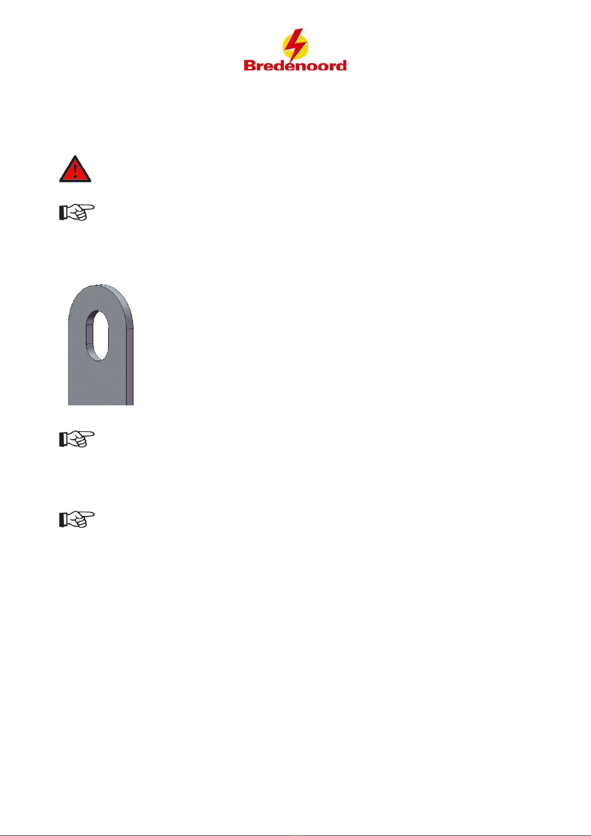
Moving by means of the lifting eye (if applicable)
The Light Tower can be lifted by means of the lifting eye with a chain and a suitable crane. Never attach the
chain directly to the lifting eye due to damage but use a closable hook.
Lifting eye (if applicable)
Use only approved lifting equipment and check the lifting eye and lifting equipment for damage.
Moving by means of a forklift
When moving the Light Tower by means of a forklift it’s important to keep the Light Tower as straight as
possible to prevent falling from the lifting forks.
Keep in mind during lifting that the centre of gravity of the Light Tower lies beneath the lifting eye.

Volledige bedieningshandleiding A
© Bredenoord bv 2016
15
9Expiring of the warranty
The warranty of the Light Tower provided by Bredenoord expires directly if:
·The maintenance on the Light Tower is not carried out as specified by the manufacturer.
·(Safety) components of the Light Tower are removed and not placed back before the Light Tower is being put in
operation.
·Components and/or accessories are added to the Light Tower without written permission from the
manufacturer.
·The Light Tower is used for other purposes than intended by the manufacturer.
·The Light Tower is not installed, moved, operated and/or put into operation, as described in this manual.
·Modifications are being made without written permission from the manufacturer.
·The use is in contrary with the instructions prescribed by this manual.
·The Light Tower is incorrectly attached and/or linked to other components and/or machines.
·The Light Tower is incorrectly connected in the complete installation.
Volledige bedieningshandleiding A
© Bredenoord bv 2016
16
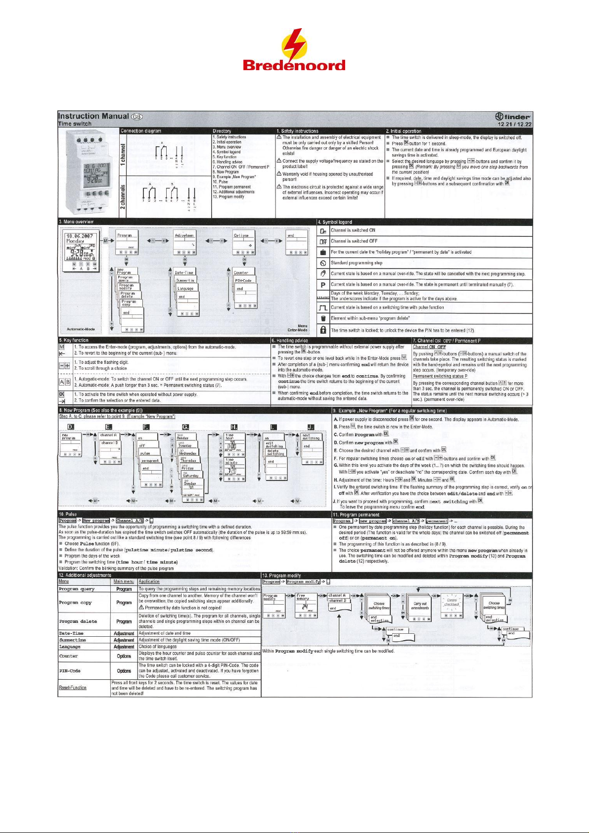
10 Appendix: Timer
This manual suits for next models
1
Table of contents
Other Bredenoord Industrial Equipment manuals


