Breezaire WKS4000 Series User manual
8610 Production AvenuelSan Diego, California 92121l(858)566-7465lFax (858)566-1943lWWW.BREEZAIRE.COM
WKS 4000 SERIES
(USA only)
--INSTALLATION INSTRUCTIONS--
Thank you for choosing a BREEZAIRE cooling unit. We believe our products are
the best on the market and will provide many years of trouble free service.
Please take a few minutes and read this entire instruction before beginning the installation.
MODEL_
__
__
__
__
__
__
__
__
__
__
__
__
__
__
__
__
__
__
__
__
_SERIAL NUMBER_
__
__
__
__
__
__
__
__
__
__
__
__
__
__
__
__
__
__
__
_
INSTALLED BY _
__
__
__
__
__
__
__
__
__
__
__
__
__
__
__
__
__
__
__
__
__
__
__
__
__
__
__
__
_DATE_
__
__
__
__
__
__
__
__
__
__
__
__
__
__
_
While great effort has been made to provide accurate guidelines, BREEZAIRE cannot warrant its units to properly cool a particular enclosure. Customers are cautioned
that enclosure construction, unit location and many other factors can affect the operation and performance of the unit. Therefore the suitability of the unit for a specific
enclosure or application must be determined by the customer and cannot be warranted by BREEZAIRE.
Before removing the cooling unit from the box, please inspect for damage which might have been
incurred during shipping. If damage is found, notify the Freight Company immediately.
BREEZAIRE is not responsible for any damages incurred during shipping.

WKS 4000 12 /05 PG. 2
INSTALLATION INSTRUCTIONS
FOR WKS 4000 SERIES COOLING UNITS
The BREEZAIRE WK Series cooling units are designed to, when installed in a properly constructed enclosure,
provide a constant, selectable temperature between 48°F and 62°F while reducing the excess relative humidity to
the proper 50% to 75%. BREEZAIRE cooling units are designed to lower the temperature, while removing
only excessive moisture. In a properly constructed enclosure this process can raise the relative humidity. The
unit does not add moisture to the enclosure. The unit does not include a heating system and will not warm the
enclosure. The WKS Series is not intended to cool service cabinets, which are maintained at lower temperatures
and opened or entered frequently.
The WKS Series cooling unit, is shipped as components, not a working cooling system. Only after a qualified
refrigeration installer has properly connected these components, pressured tested, evacuated, charged with
refrigerant and tested their installation, can the unit be considered a cooling system. Proper installation is critical
to the performance, reliability and longevity of the system. For this reason, BREEZAIRE can only warrant the
quality of the WKS components. The installation and proper operation must be warranted by the installer.
Before installation is to begin, the purchaser and installer should carefully read the enclosed Limited Warranty.
ENCLOSURE CONSTRUCTION
To use the below SIZING GUIDE, the enclosure to be cooled must be built to the following minimum
specifications. If the enclosure is not built to these specifications, consult your BREEZAIRE dealer for
assistance in choosing the correct unit. BREEZAIRE units are not warranted to cool a specific enclosure.
All interior walls and floor should have a vapor barrier and a minimum of R-11 insulation. All exterior wall's
insulation values should be a minimum of R-19. The ceiling should have vapor barrier and a minimum of R-19
insulation. The vapor barrier should be installed on the warm side of the insulation. There should be no glass
windows or doors.
FAll joints, door frames, electrical outlets or switches and any pipes or vents which go through the enclosure
should be sealed to prevent air and moisture leakage into the room. Concrete, rock and brick are not
insulation or moisture barriers.
FDoors into the enclosure should be of minimum size, insulated to R-11 and be tightly sealed with a high
quality weather stripping. Be sure to seal the bottom of the door and the fill gap between the door's frame
and wall before installing the cap molding.
FEnclosure lighting should be of low wattage, with a timer to insure lights are not left on when the enclosure is
unoccupied. Recessed lighting should not be used as they will allow outside air to enter the enclosure.
FThe ambient temperature surrounding the enclosure should not exceed the desired cellar's temperature by
more than 25°F. No enclosure wall should receive direct sunlight or strong wind.
SIZING GUIDE & SPECIFICATIONS
This guide is to be used only for enclosures meeting the above construction requirements.
BREEZAIRE
Model Enclosure
Volume Electrical Dimensions (inches) Weight
WKS4000 Fan/Coil
(Figure 1) 1.5 Amps 14.25w x 19.75h x 12.375d 45 lbs
WKS4000 Condenser
(Figure 2)
1000 cu.ft. 7.5 Amps 14.25w x 19.75h x 12.375d 55 lbs
Note: All units are 115 Volt, 60 Hz

WKS 4000 12 /05 PG. 3
INSTALLATION
BREEZAIRE recommends the use of a licensed refrigeration technician to install the WKS systems. Installation
of the unit's line set through a fire rated wall must be done in accordance with your local building inspector and
building codes.
FIf your installation cannot be performed in accordance with these instructions contact your
dealer.
FThe unit must be installed in the upright position and are not designed to have duct systems attached to
either unit. Do not drill any holes into the cooling unit. This may damage the unit, promote rust, and will
void the warranty.
FBefore installing the unit, inspect it again for any shipping damage. The WKS systems consist of two
components, the fan/coil unit (Figure 1) and the condensing unit (Figure 2). The condensing unit includes
the compressor, condenser coil, fan assembly, receiver tank and two service ports. The fan/coil unit
includes an internal, adjustable thermostat (48° to 62°F), solenoid valve, expansion valve, evaporator
coil, and fan assembly. The sight glass and strainer/dryer are separate pieces supplied with the unit.
FMounting the fan/coil unit: The fan/coil unit should be mounted within six inches of the ceiling and as
close to the horizontal center of the wall as possible. If the unit must be mounted below the mid point of
the wall, exchange the upper front grill with the blank off plate on the top of the unit. (Figure 1) Airflow to
and from the unit must be unobstructed for a minimum of 3 feet. The unit is mounted to the wall using the
four slotted holes in the rear plate. The top holes should be approximately 10" from the ceiling. Mount
the unit to a solid part of the wall using ¼" lags or bolts. If necessary, attach two horizontal furring strips,
at least 1" thick, solidly to the studs and attach the unit to the furring strips. Provisions must be made for
passing the tubing set, wiring and drain tube through the wall.
FMounting the condensing unit: Remember, unit installation location is not only important inside the wine
cellar, but just as important is where the condensing unit's warm exhaust air is being rejected. This is a
mechanical piece of equipment, it will make noise and produce heat from the warm exhaust air outlets
(Figures 2). Place the condensing unit on a solid foundation in a location with at least 1-foot of clearance
on all sides and the warm exhausting air to be unobstructed for at least 3 feet. This location should be an
area where the temperature is not higher than 90°F or lower than 20°F. (Note: Condensing units mounted
in areas with higher temperatures will degrade the performance of entire unit.) Inappropriate locations for
mounting the condensing unit includes laundry rooms, closets, bathrooms, garages, crawl spaces, attics
and humid basements. The condensing unit should be elevated to avoid any possible flooding and shaded
from direct sun light. Remove the screws and the upper cover. Do not open the access valves.
FPlumbing the system: The two units are connected by a 1/4 inch "liquid line" copper tube, and a 3/8
inch "suction line" copper tube. (Figure 1) The line-set should have a maximum calculated length of 100
ft. for each line. Reduce the line-set length by 10 feet for every 90° bend. [Calculated Length = Linear
length + 10 ft. for every 90' bend] (Note: Enclose both the suction [Gas] and discharge [Liquid] lines in
one flexible insulation jacket to promote heat exchange and prevent condensation from forming on the
lines.) Remove the cores from the access valves before soldering tubing to the valves. Caution: hold
charging valve assembly body with an appropriate wrench when removing or tightening the cap
or opening and closing the valve. The sight glass and strainer/dryer are separate pieces supplied with
the unit. The sight glass and strainer/dryer should be connected to the condensing unit's liquid line as
close as possible to unit.
WKS 4000 12 /05 PG. 4
If the condensing unit is mounted higher than the fan/coil unit, a P-trap must be installed in the suction and
discharge lines at the condensing unit. The fan /coil unit is equipped with a 1/2 inch OD plastic fitting for
removal of condensate. Connect a 1/2 inch I.D. vinyl hose to the fitting and route the hose to an
appropriate drain. Ensure the 1/2 inch I.D. vinyl hose has an air break installed within 2 to 10 inches from
unit connection and/or in accordance with local building codes. A condensate pump is required if the
vinyl drain hose has any vertical rise, significant horizontal or near horizontal run.
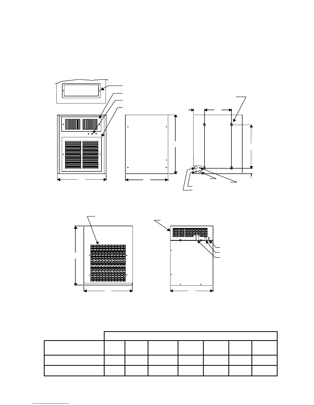
Dimensions (inches)
BREEZAIRE
Models (A) (B) (C ) (D) (E) (F) (G)
WKS 4000 Fan/Coil
(Figure 1) 14.25 19.75 12.375 14.5 1.875 3.125 7.875
WKS 4000 Condenser
(Figure 2) 14.25 19.75 12.375 N/A N/A N/A N/A
CONDENSING UNIT
MOUNTING HOLES
BACK VIEW
DRAIN
3/8" SUCTION LINE
ELECTRICAL 115 VOLTS 60 Hz.
1/4" LIQUID LINE
BLANK OFF PLATE
UPPER GRILL (COLD AIR DISCHARGE)
RIGHT SIDE
COOL AIR INTAKE
1/4" LIQUID LINE
3/8" SUCTION LINE
AC
BD
E
FG
A
B
C
THERMOSTAT
LOWER GRILL (COLD AIR INTAKE)
WARM EXHAUST
AIR OUTLET (3 SIDES ONLY)
ELECTRICAL
FAN/COIL UNIT
(FIGURE 1)
(FIGURE 2)
115 VOLTS 60 Hz.
WKS 4000 12 /05 PG. 5
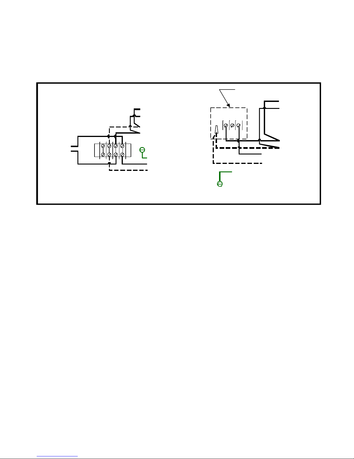
FWiring the system: Wire the system in accordance with local code and the wiring diagrams. Electrical
connections are made to the terminal strip in the fan/coil and the condensing unit. (Figure 3) Both the fan/coil
and condensing unit requires a standard 110-volt, 60 Hz properly grounded electrical source. Each circuit
must be rated for minimum amperes in accordance with sizing guide.
WARNING: THE COMPLETED SYSTEM MUST BE PRESSURED TESTED FOR A
MINIMUM OF 6 HOURS AND THEN EVACUATED TO HOLD A 250 MICRON VACUUM,
AFTER THE PUMP IS TURNED OFF, FOR A MINIMUM OF 15 MINUTES. (NOTE: THIS
COULD TAKE 6 HRS TO ACHIEVE) ANY LEAKS DISCOVERED AFTER REFRIGERANT
CHARGING IS THE SOLE RESPONSIBILITY OF THE INSTALLER.
FCharging the system: After all components have been connected, reinstall the access valve cores and
open the valves. With electrical power connected to the fan/coil unit energizing the solenoid valve, pressure
test the complete system for a minimum of six hours. If no leaks are found, leave the fan/coil and solenoid
valve energized, evacuate the system through both the liquid and suction service ports for a minimum of six
hours. Replace the insulation and cover on the fan/coil unit.
With electrical power connected to both the condensing unit and the fan/coil, slowly feed refrigerant (R12 or
R414B) into the suction service port. As the suction pressure rises to 30 psi the condensing unit will start.
Continue feeding refrigerant while maintaining a pressure above 15 psi to prevent the compressor from short
cycling. When the system is correctly charged the suction pressure should correspond to an evaporating
temperature 35°F when the enclosure temperature is at 55°F. Feed refrigerant until the sight glass is clear of
bubbles if using R12. If R414B is being used there may be some bubbles in the sight glass.
Allow the system to operate for several hours and than check the refrigerant level in the sight
glass again. Additional refrigerant may be required as the temperature of the enclosure is
lowered to approximately 55° or the ambient temperature at the condensing unit rises above the
temperature at which the unit was charged.
THERMOSTAT
GROUND (GREEN)
SOLENOID VALVE
FAN MOTOR
FAN/COIL WIRING
COMPRESSOR
FAN MOTOR
GROUND (GREEN)
LOW PRESSURE CONTROL
CONDENSER WIRING
LINE (BLACK)
COMMON (WHITE)
4 2 1
(FIGURE 3)
LINE (BLACK)
COMMON (WHITE)
Table of contents


