Bren-Tronics ALT 170C Installation manual

BREN-TR
O
P: 631-499-51
5
www.bren-tro
850084 Rev D
O
NICS, INC.
5
5 | F: 631-499-
5
nics.com
5
504
O
P
BT
C
NSN
:
Copy
r
P
ERATI
C
-70844
-
: N/A
r
ight © Bren-
T
ON M
A
-
2
T
ronics, Inc.
2
A
NUA
L
2
015
L
BREN-TRONICS, INC.
10 Brayton Court
Commack, NY 11725
P: 631-499-5155 | F: 631-499-5504
www.bren-tronics.com Page 2of 25
ALT 170C
(BTC-70844-2)
PR4G WORKSHOP CHARGER
OPERATION MANUAL
850084 REV D
Data presented in this document is subject to change without notice
WARNING
HIGH VOLTAGES ARE PRESENT IN THE
OPERATION OF THIS EQUIPMENT
Avoid contact with AC supply voltage connections during installation, operation
or maintenance of the battery charger.
CAUTION
ACID CONTAMINATES NICKEL-CADMIUM, LITHIUM-ION,
LITHIUM-POLYMER and NICKEL-METAL HYDRIDE BATTERIES
Every effort must be made to keep Nickel-Cadmium, Lithium-Ion, Lithium
Polymer and Nickel-Metal Hydride batteries as far away as possible from Lead-
Acid batteries because Lead-Acid batteries contain sulfuric acid. Do Not use the
same tools and materials, such as screwdrivers, wrenches, syringes,
hydrometers, and gloves for both types of batteries. Any trace of acid or acid
fumes will permanently damage Nickel-Cadmium, Lithium-Ion, Lithium Polymer
and Nickel-Metal Hydride batteries on contact.
WARNING
NO SMOKING IS PERMITTED NEAR THE CHARGING STATION
Batteries can produce explosive gases during charging or discharge cycles.
Never smoke or allow open flames near the charging station.
NOTICE TO PERSONS RECEIVING THIS DRAWING
AND/OR TECHNICAL INFORMATION:
BREN-TRONICS, INC. claims proprietary rights in the material disclosed
herein. This drawing and/or technical information is issued in confidence
for information only and may not be reproduced or used to manufacture
anything shown or referred to heron without direct permission from BREN-
TRONICS INC. to the user. This drawing and/or technical information is
loaned for mutual assurance and is subject to recall by BREN-TRONICS
INC. at any time.
This drawing and/or technical information
is the property of BREN-TRONICS, INC.

BREN-TRONICS, INC.
10 Brayton Court
Commack, NY 11725
P: 631-499-5155 | F: 631-499-5504
www.bren-tronics.com Page 3of 25
ALT 170C
(BTC-70844-2)
PR4G WORKSHOP CHARGER
OPERATION MANUAL
850084 REV D
Data presented in this document is subject to change without notice
ALT 170C Operation Manual
Table of Contents
1INTRODUCTION ................................................................................................... 4
1-1 SCOPE ......................................................................................................... 4
1-2 TECHNICAL SPECIFICATIONS................................................................... 5
1-3 DECLARATION OF CONFORMITY ............................................................. 6
1-4 ACCESSORIES............................................................................................ 7
1-5 CHARGE CYCLE DESCRIPTION ................................................................ 9
1-6 SEQUENTIAL CHARGING DESCRIPTION ............................................... 10
1-7 UPGRADING CHARGER SOFTWARE...................................................... 11
2OPERATING PROCEDURES.............................................................................. 12
2-1 PANEL CONTROLS AND INDICATORS ................................................... 12
2-2 PRELIMINARY SETUP PROCEDURES .................................................... 14
2-3 CHARGING BATTERIES ........................................................................... 15
2-4 BATTERY REVITALIZATION AND DESTORAGE ..................................... 15
2-5 BATTERY CHARGER COVER LABEL ...................................................... 17
2-6 SOLID RED LED TROUBLESHOOTING ................................................... 18
2-7 OPERATION IN EXTREME ENVIRONMENTAL CONDITIONS................. 18
2-8 PREPARATION FOR MOVEMENT............................................................ 19
2-10 BATTERY CAPACITY RETENTION........................................................... 19
2-11 BATTERY STORAGE................................................................................. 20
3OPERATOR MAINTENANCE INSTRUCTIONS .................................................. 21
3-1 INTRODUCTION ........................................................................................ 21
3-2 CLEANING ................................................................................................. 21
3-3 INSPECTION.............................................................................................. 21
3-4 BASIC FUNCTIONAL TEST ....................................................................... 22
3-5 SIMPLIFIED OPERATOR TROUBLESHOOTING PROCEDURES............ 23
3-6 WARRANTY / REPAIR INFORMATION..................................................... 25
3-7 UPGRADE / UPDATE INFORMATION ...................................................... 25

BREN-TRONICS, INC.
10 Brayton Court
Commack, NY 11725
P: 631-499-5155 | F: 631-499-5504
www.bren-tronics.com Page 4of 25
ALT 170C
(BTC-70844-2)
PR4G WORKSHOP CHARGER
OPERATION MANUAL
850084 REV D
Data presented in this document is subject to change without notice
1 INTRODUCTION
1-1 SCOPE
The ALT 170C Universal Workshop Charger (P/N BTC-70844-2) is a state-of-the-art,
high performance lightweight portable battery charger designed for field deployment or
shop usage. It provides fast reactivation of various rechargeable batteries. It is
capable of sequentially charging up to eight batteries completely unattended.
The ALT 170C is simple to use by design. Without any user intervention, the ALT
170C charges up to eight batteries. It automatically identifies the specific battery type
and provides the appropriate charge profile. Based on the current operating
environment, the ALT 170C automatically customizes the charge profile to provide the
quickest charge in a safe manner. The charge status for each of the eight batteries is
conveyed to the user via three easy-to-understand panel mounted LED indicators
(amber – CHARGE, green – READY and red – FAULT).
The ALT 170C is universal by design. It can readily use either AC or DC input power –
whichever is most convenient for the user. The universal AC input fully allows 85-264
Vac and 47-420Hz operation without any adjustment or user intervention. Additionally,
the DC input power permits a range of 20-33Vdc, standard on most military vehicles.
The ALT 170C is adaptive by design. It is microprocessor controlled and is presently
programmed to automatically charge over 80 different battery types as listed in Table
1. With the appropriate battery adapter, however, it can be readily reprogrammed via
RS232 software upgrade port in the field to charge a countless number of additional
battery types and chemistries including: Nickel Metal Hydride, Nickel Cadmium,
Lithium Ion, and Lithium Polymer. The ALT 170C also provides a Revitalization
function for Nickel Cadmium batteries and a Destorage function for Lithium Ion
batteries.
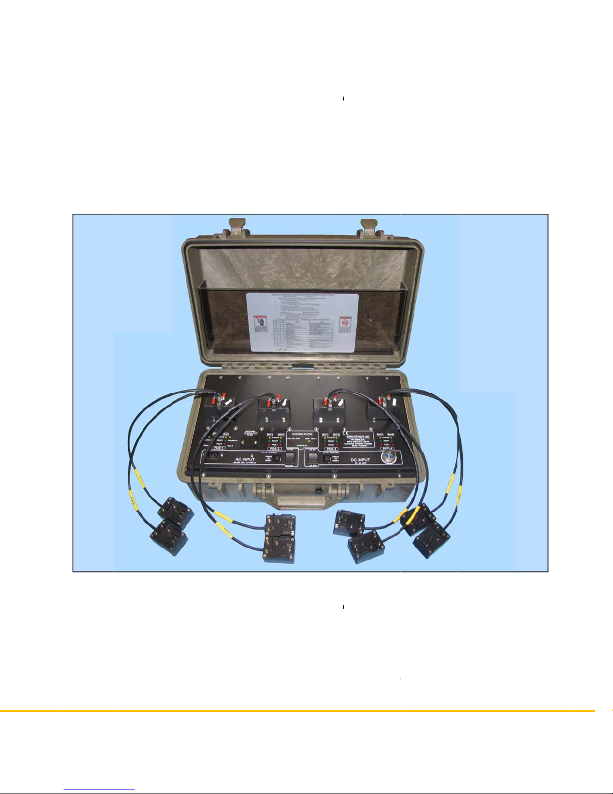
The battery charger components are housed in a durable, non-conductive ABS
equipment case, as shown in Figure 1. The assembled unit is watertight when the
cover is securely latched and the pressure equalization valve on the front of the case
(near the carrying handle) is closed. The Charger is a standard BTC-70844 shipped
with four BTA-70589A Adapters.

BREN-TRONICS, INC.
10 Brayton Court
Commack, NY 11725
P: 631-499-5155 | F: 631-499-5504
www.bren-tronics.com Page 5of 25
ALT 170C
(BTC-70844-2)
PR4G WORKSHOP CHARGER
OPERATION MANUAL
850084 REV D
Data presented in this document is subject to change without notice
1-2 TECHNICAL SPECIFICATIONS
Dimensions ...........................……... 580 mm W x 375 mm D x 230 mm H
Weight (less adapters and cables)….…...12.5 kg
(with adapters and cables)……… 15 kg
Power Requirements
AC operation .....................……… Automatic selection: 85-264Vac, single-phase,
47-440Hz, 3A (max)
1.95m detachable three-wire power cord
Included.
DC operation ....................……… 20-33Vdc, 15A (max)
1.55m DC cable Assembly Included.
Charging Output Voltage.......……… Automatically selected for each battery type
Duty Cycle.............................…….... Continuous
Protective Features…………………. Resettable circuit breakers:
AC – 7A
DC – 20A
Operating Temp. Range …………… -10˚C to 50˚C
Storage Temp. Range ..........………. -40˚C to 70˚C
Case Material........................………. ABS (Acrylonitrile Butadiene Styrene)
Case Color............................………. Olive Drab #34088 per Fed-Std-595B
Shipment...............................………. No restrictions

BREN-
T
10 Brayto
Commac
k
P: 631-4
9
www.bre
n
T
RONICS, I
N
n Court
k
, NY 11725
9
9-5155 | F: 631-
n
-tronics.com
1-3
N
C.
499-5504
DECLA
R
R
ATION
O
Page 6of 25
O
F CONF
O
AL
T
(BT
C
PR
4
OP
E
850
0
Dat
a
O
RMIT
Y
T
170C
C
-70844-2)
4
G WORKSHO
P
E
RATION MAN
U
0
84 REV D
a
presented in t
h
P
CHARGER
U
AL
h
is document is
s
s
ubject to chang
e
e
without notice

BREN-TRONICS, INC.
10 Brayton Court
Commack, NY 11725
P: 631-499-5155 | F: 631-499-5504
www.bren-tronics.com Page 7of 25
ALT 170C
(BTC-70844-2)
PR4G WORKSHOP CHARGER
OPERATION MANUAL
850084 REV D
Data presented in this document is subject to change without notice
1-4 ACCESSORIES
Table 1 shows the various batteries and appropriate adapters the ALT 170C can
charge as of the writing of this document.
Table 1 - Supported Batteries and Adapters
ADAPTER ADAPTER NSN BATTERY TYPE BATTERY NSN
BTA-70582 --- ALI 124
ALI 142/BA-682A
BA-682B
BA-684A
NiCd
Li Ion
Li Ion
Li Ion
---
6140-14-328-2258
6140-14-561-1542
6140-14-529-5971
BTA-70582-1 --- ALI 142/BA-682A
BA-682B
BA-684A
Li Ion
Li Ion
Li Ion
6140-14-328-2258
6140-14-561-1542
6140-14-529-5971
BTA-70589 6130-01-564-8116 ALI 116
ALI 124
ALI 142/BA-682A
ALI 143/BA-687A
ALI 243
BA-684A
BA-685A
BA-682B
ALI 147
ALI 247
NiCd
NiCd
Li Ion
Li Ion
Li Ion
Li Ion
Li Ion
Li Ion
Li Ion
Li Ion
---
---
6140-14-328-2258
6140-14-530-0061
6140-14-553-4062
6140-14-529-5971
6140-14-529-5973
6140-14-561-1542
---
---
BTA-70589A --- ALI 142/BA-682A
ALI 143/BA-687A
ALI 243
BA-684A
BA-685A
BA-682B
ALI 147
ALI 247
Li Ion
Li Ion
Li Ion
Li Ion
Li Ion
Li Ion
Li Ion
Li Ion
6140-14-328-2258
6140-14-530-0061
6140-14-553-4062
6140-14-529-5971
6140-14-529-5973
6140-14-561-1542
---
---
NOTES:
1) The ALT 170 (BTC-70565) Adapter (BTA-70480/3) is not compatible with this charger and can
only be used in the ALT 170.
2) These Adapters and Batteries are supported by Charger Revision K software.
3) Additional Adapters are available, but may require additional software certification.
4) The ALT 170C is shipped from the factory with four BTA-70589A Adapters.

BREN-
T
10 Brayto
Commac
k
P: 631-4
9
www.bre
n
T
RONICS, I
N
n Court
k
, NY 11725
9
9-5155 | F: 631-
n
-tronics.com
I
E
I
E
I
E
D
D
P
F
N
C.
499-5504
D
E
C
A
C POW
E
E
C AC POW
E
E
C AC POW
E
D
C POWER
C
D
C POWER
C
P
R4G ADAP
T
F
igure 1-4.1
Figure 1-4.3
Table
2
D
ESCRIPTIO
N
E
R CORD U
S
E
R CORD E
U
E
R CORD U
K
C
ABLE (Ring
C
ABLE (Allig
a
T
ER
BTA-70844-
2
BTA-70589
A
Page 8of 25
2
- Power C
a
N
S
U
K
Lugs)
a
tor Clips)
2
4
A
AL
T
(BT
C
PR
4
OP
E
850
0
Dat
a
a
bles and Ot
ORDER
N
591
590
2
5902
3
BTA-7
0
BTA-70
8
BTA-
7
T
170C
C
-70844-2)
4
G WORKSHO
P
E
RATION MAN
U
0
84 REV D
a
presented in t
h
her Access
o
NUMBER
609
2
33-3
3
3-UK
0
844-24
8
44-24AL
7
0589
A
Figur
e
P
CHARGER
U
AL
h
is document is
s
o
ries
PART N
U
--
--
--
--
--
--
e 1-4.2 BTA
s
ubject to chang
e
U
MBER
-
-
-
-
-
-
-70844-24A
L
e
without notice
L

BREN-TRONICS, INC.
10 Brayton Court
Commack, NY 11725
P: 631-499-5155 | F: 631-499-5504
www.bren-tronics.com Page 9of 25
ALT 170C
(BTC-70844-2)
PR4G WORKSHOP CHARGER
OPERATION MANUAL
850084 REV D
Data presented in this document is subject to change without notice
1-5 CHARGE CYCLE DESCRIPTION
Each of the battery types that are capable of being charged by the Charger is
connected to the charger via their respective battery adapter cable. Each adapter can
charge two batteries simultaneously. The appropriate battery adapter is installed on
the control panel and serves as the electrical interface between the batteries being
charged and the charger circuits. The battery charger control circuits constantly
monitor the following battery conditions during the charge cycle, as appropriate, to
ensure that the battery is properly being charged:
a. Temperature (T)
b. Voltage (V)
c. Current (I)
d. Time (t)
e. Voltage change (∆V)
f. Temperature rate of change (∆T/∆t)
The charger operation during a typical charge sequence is automatic and the battery
charge status is displayed to the user by the panel LED indicators as follows:
a. Detection - The charger tries to detect a battery in an adapter. The CHARGE
LED (amber) blinks slowly during this process.
b. Pre-charge – The charger brings the battery voltage up to a safe level before
the rapid charge process begins. This step may take several minutes for a very
discharged battery. The CHARGE LED (amber) blinks rapidly during this
process.
c. Fast Charge – A timed fast charge cycle brings the battery to approximately
90% of full charge capacity. The CHARGE LED (amber) is lit solid during this
process.
d. Ready – The fast charge cycle is complete. The Battery may be removed and
used at this time. The READY LED (green) is lit steadily at this time.
e. Trickle / Top-off – When fast charge is complete, the charger will top off of the
battery to 100%. Each battery is charged for five minutes at a time. For Lithium
Ion and Lithium Polymer batteries the top-off cycle will stop after the battery is
100% charged. For all other types, the Trickle / Top-off cycle is repeated
indefinitely to keep the battery at 100% charge. Leaving the battery on the
charger will not harm the battery. The battery may be removed and used at this
time. The READY LED (green) blinks during this process.
The Battery may be removed and used at anytime during the charge cycle without
damage to the charger or battery. The state-of-charge indicator (SOC) will display the
battery condition. NOTE
After removing a battery from the charger, wait for the
corresponding battery status LED’s to turn off before installing a
new battery.
BREN-
T
10 Brayto
Commac
k
P: 631-4
9
www.bre
n
T
RONICS, I
N
n Court
k
, NY 11725
9
9-5155 | F: 631-
n
-tronics.com
1-6
The A
L
eight
b
of-cha
r
Two in
time.
U
up to t
h
Ports i
s
During
neces
s
batter
y
numer
i
batter
y
batter
y
(if nec
e
N
C.
499-5504
SEQUE
N
L
T 170C is
b
atteries in
a
r
ge.
dependent
U
pon char
g
h
ree additi
o
s
performe
d
the seque
n
s
ary to cha
r
y
will charg
e
i
cal order (
P
y
in queue.
y
that has a
e
ssary) for
N
TIAL C
H
a dual-cha
a
pproxima
t
charging
c
g
e completi
o
nal batteri
e
d
complete
Fig
u
n
cing proc
e
r
ge each b
a
e
quicker t
h
P
ort 1 – P
o
As the ch
a
lready bee
n
approxima
t
Page 10 of 2
5
H
ARGING
nnel sequ
e
t
ely eight h
o
c
hannels, d
e
on of the fi
r
e
s that are
ly automat
i
u
re 1 –
A
LT 1
e
ss, the ch
a
a
ttery to gr
e
h
an a totall
y
o
rt 2 – Port
a
nnel sequ
e
n
charged,
t
ely 5 minu
5
AL
T
(BT
C
PR
4
OP
E
850
0
Dat
a
DESCRI
P
e
ntial charg
e
o
urs – dep
e
e
signated
A
r
st battery,
waiting in
q
i
c and requ
70C Typical
a
nnel spen
d
e
ater than
9
y
discharg
e
3 – Port 4
–
e
nces thro
u
it will atte
m
t
es and th
e
T
170C
C
-70844-2)
4
G WORKSHO
P
E
RATION MAN
U
0
84 REV D
a
presented in t
h
IP
TION
er. It auto
m
e
nding on
t
A
and B, c
a
each chan
q
ueue. Se
q
u
ires no int
e
Configurati
o
ds only as
9
0% capa
c
e
d battery.
–
Port 1 –
P
u
gh the fou
m
pt to Trick
e
n continue
P
CHARGER
U
AL
h
is document is
s
m
atically c
h
t
he battery
a
n charge
o
nel seque
n
q
uencing t
o
e
rvention b
y
o
n
much time
c
ity. A parti
It then seq
P
ort 2, etc.
)
r Ports an
d
k
le or Top-
o
e
onto the n
s
ubject to chang
e
h
arges up t
o
type and s
t
o
ne battery
n
tially char
g
o
the other
t
y
the user.
as is
ally charg
e
uences, in
)
, to the ne
x
d
comes to
o
ff that batt
e
ext Port.
e
without notice
o
t
ate-
at a
g
es
t
hree
e
d
x
t
a
e
ry

BREN-TRONICS, INC.
10 Brayton Court
Commack, NY 11725
P: 631-499-5155 | F: 631-499-5504
www.bren-tronics.com Page 11 of 25
ALT 170C
(BTC-70844-2)
PR4G WORKSHOP CHARGER
OPERATION MANUAL
850084 REV D
Data presented in this document is subject to change without notice
This means batteries added later may charge first, depending on their position on the
charger. If certain batteries must be charged first, then this must be taken in to
account. When the charger moves to a position it will charge or top off the battery at
that position, as necessary. This allows batteries to be added or removed at anytime.
The charger automatically keeps track of the current state of each Port.
1-7 UPGRADING CHARGER SOFTWARE
The software in the charger is readily field upgradeable. By loading new software into
the charger, it is possible to alter its operation and add or change the charging profiles
for the batteries. Loading new software into the charge is accomplished via the use of
a standard RS232 interface of a personal computer (PC). Utilizing special software
running on the PC in conjunction with the boot program resident within the charger, a
two-way communication link is established and the revised operational parameters
and battery charge profiles can be loaded into the charger. Specific instructions for
upgrading the ALT 170C software are provided with the software upgrades.

BREN-TRONICS, INC.
10 Brayton Court
Commack, NY 11725
P: 631-499-5155 | F: 631-499-5504
www.bren-tronics.com Page 12 of 25
ALT 170C
(BTC-70844-2)
PR4G WORKSHOP CHARGER
OPERATION MANUAL
850084 REV D
Data presented in this document is subject to change without notice
2 OPERATING PROCEDURES
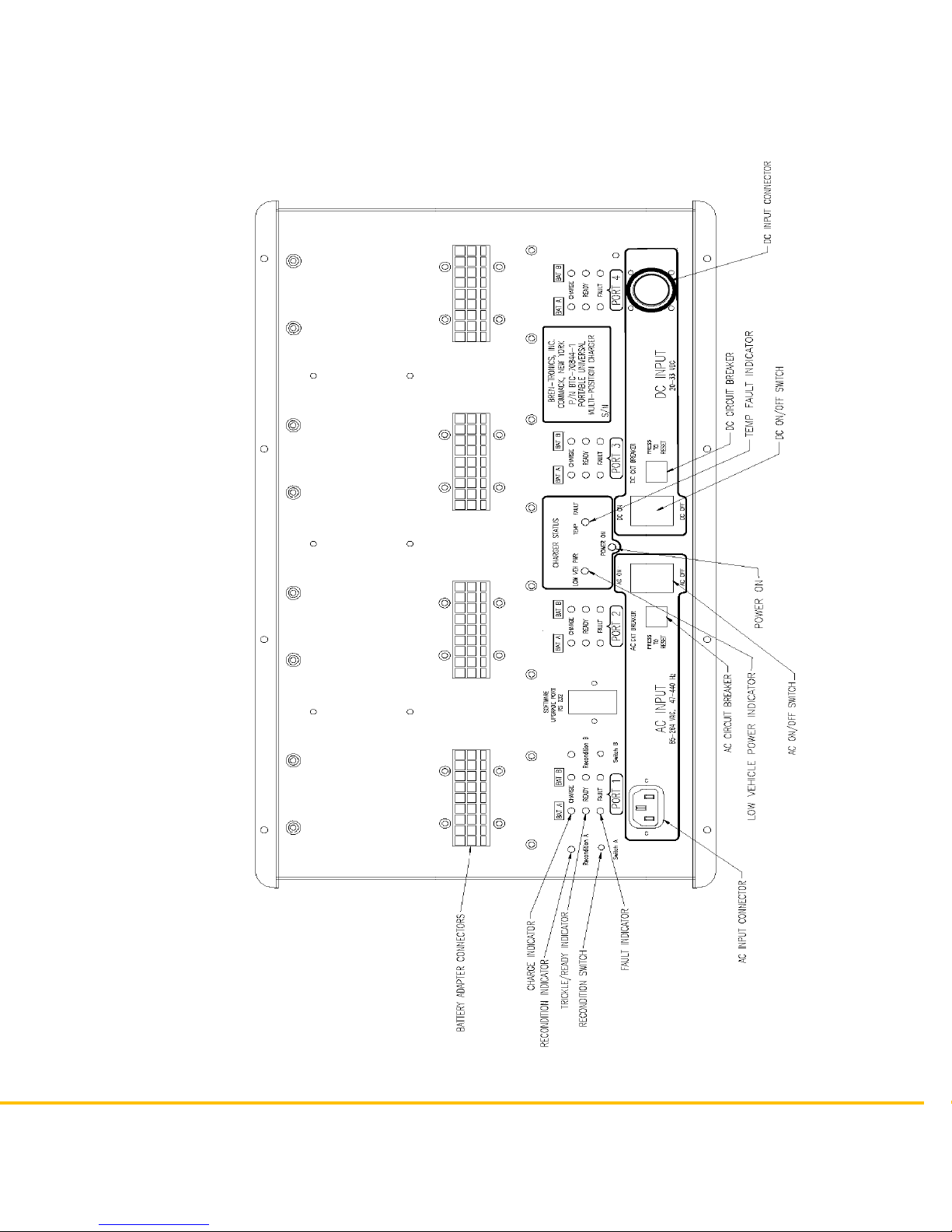
2-1 PANEL CONTROLS AND INDICATORS
Battery charger panel components are described below and shown in Figure 2-1.
Item Function
AC ON/OFF power switch...... Turns battery charger AC supply on or off.
AC CKT BREAKER................ Turns power to the charger off in an overload condition.
Remove the overload condition and push to reset.
LOW VEH POWER LED ........ The Low Vehicle power indicator lights when external
DC power is too low to charge batteries. The charger
will stop charging batteries.
TEMP FAULT LED................. The Temperature Fault indicator lights when charger
temperature is too high (50°C) or too low (-10°C). The
charger will stop charging batteries.
DC ON/OFF POWER SWITCH Turns battery charger DC supply on or off. If both AC
and DC power are connected and both power switches
are on, then DC Power will be used by the charger.
DC CKT BREAKER................ Turns power to the charger off in an overload condition.
Remove the overload condition and push to reset.
CHARGE LED........................ The Amber LED lights steady while the associated
battery is being fast-charged. A slow blinking indication
means the charger is trying to find a battery at the
select position. A fast blinking indication means the
charger is precondition the battery before charging it.
READY LED........................... The Green LED indicates the associated battery is fully
charged and ready to be removed for use. Steady light
means the battery has completed fast charge. A
blinking indication means the battery is being topped
off.
FAULT LED............................ If the Red LED lights steady the associated battery, or
adapter plate, is defective or will not accept charge. A
blinking indication means the battery’s temperature
sensor or communication connection is not making
contact with the adapter.
RECONDITION Switch…….…Activates NiCad Revitalization or Li-Ion Destorage
function with battery in PORT 1.
RECONDITION LED………….Lights amber during revitalization / destorage process.
BATTERY ADAPTER PORT.. Provides interface connection for battery adapters.
AC INPUT Connector............. Input connection for AC cable assembly. (Provided)
DC INPUT Connector............. Input connection for DC cable assembly. (Optional)
BREN-TRONICS, INC.
10 Brayton Court
Commack, NY 11725
P: 631-499-5155 | F: 631-499-5504
www.bren-tronics.com Page 13 of 25
ALT 170C
(BTC-70844-2)
PR4G WORKSHOP CHARGER
OPERATION MANUAL
850084 REV D
Data presented in this document is subject to change without notice
Figure 2-1 – ALT 170C Front Panel Components

BREN-TRONICS, INC.
10 Brayton Court
Commack, NY 11725
P: 631-499-5155 | F: 631-499-5504
www.bren-tronics.com Page 14 of 25
ALT 170C
(BTC-70844-2)
PR4G WORKSHOP CHARGER
OPERATION MANUAL
850084 REV D
Data presented in this document is subject to change without notice
2-2 PRELIMINARY SETUP PROCEDURES
Step 1. Place the unit on the work surface. Unscrew the pressure equalization valve
(near the carrying handle) in a counterclockwise direction about two full
turns. Unfasten latches and open cover.
Step 2. Set AC and DC power ON-OFF switches, to OFF position.
Step 3. The Cover may be removed by removing both hinge pins with pliers.
Step 4. For AC operation: Connect AC power cord from AC INPUT connector to
power source and set AC power ON-OFF switch to ON position. Observe
that POWER ON LED lights, fan operates, and all LED status indicators
blink in order (amber, green, then red) briefly when power is first applied.
Step 5. For DC operation: Connect DC cable from 24 VOLT DC INPUT connector
to DC power source (via NATO slave receptacle found in most military
vehicles) and set DC power ON-OFF switch ON position. Observe that
POWER ON LED lights, fan operates, and all LED status indicators blink in
order (amber, green, then red) briefly when power is first applied. Note that
if both AC and DC power are connected that DC power will be used if the
DC power switch is on.
Step 6. Observe that only the POWER ON LED is lit.
Step 7. Install appropriate battery adapter(s) on panel for battery types to be
charged. Install the Adapter(s) by placing the back of the adapter into the
rear retainer and rotating the adapter down until the front retainer clicks over
it. Note the alignment of the pins. The connector can only plug in one way.
Do not force it. Be sure that battery adapter and connector are fully seated.
All battery adapters are interchangeable, only the battery connections are
different.
Step 8. Observe, after a short delay, the amber CHARGE LED’s blink for several
seconds at each installed adapter. This shows battery charger circuits are
initialized to the selected battery adapter and are ready to accept a battery
(or batteries) for charging. If all of the Indicators for a channel light at the
same time, the Adapter could not be recognized or the adapter is damaged.
Insure it is seated correctly.

BREN-TRONICS, INC.
10 Brayton Court
Commack, NY 11725
P: 631-499-5155 | F: 631-499-5504
www.bren-tronics.com Page 15 of 25
ALT 170C
(BTC-70844-2)
PR4G WORKSHOP CHARGER
OPERATION MANUAL
850084 REV D
Data presented in this document is subject to change without notice
2-3 CHARGING BATTERIES
Step 1. With the appropriate battery adapter installed, insert the first battery to be
charged in the Port-1 Channel-A battery location. Insure the battery is fully
seated into the adapter. Observe that CHARGE LED (amber) for the
corresponding location is lit or blinking rapidly. The CHARGE LED for the B
battery location will continue to blink if it is searching for a battery on that
channel. If the FAULT LED (red) is lit, the battery or adapter may be
defective. Check by removing battery and adapter. Then reinstall adapter
and battery. If the FAULT LED again lights, go to the Trouble Shooting
section of this Guide.
Step 2. Install the next battery into the Port-1 Channel-B battery location.
Step 3. Install the rest of the batteries. The indicators for these batteries will not
light until the charger has finished the batteries in the preceding Port
locations.
Step 4. After fast charging is complete, the CHARGE LED extinguishes and the
READY LED is lit. After the charger cycles through the batteries, it will top-
off batteries that have completed fast charge. The battery is slow-charged to
full capacity, as indicated by the blinking READY LED (green). The battery is
charged for five minutes at a time (10 minutes for dual section batteries)
then the charger will move on to the next battery. For Lithium type batteries,
the cycle will stop after the battery is 100% charged. For other types the
cycle is repeated indefinitely to keep the battery at 100% charge. As long as
the READY LED is lit (blinking or solid) the battery may be removed and
returned to service and another battery may be installed for charging.
NOTE
Battery charger power may be left ON while batteries and/or adapters
are removed or replaced. Batteries may be left in the charger for long
periods of time without damaging the batteries or charger.
2-4 BATTERY REVITALIZATION AND DESTORAGE
The procedures outlined below describe the means of invoking the Revitalization and
Destorage functions of the ALT 170C Charger as well as the sequence of operations
the charger will execute to perform the commanded tasks.
a. NiCad Revitalization (ALI 116 and ALI 124) – requires BTA-70589 Adapter
Revitalization exists on PORT 1 and is available for both the A and B channels of the
ALT 170C Charger. Due to the increased power dissipation from discharging the
batteries, this function will not operate above 40º C. The following procedure is used
to invoke the Revitalization process:

BREN-TRONICS, INC.
10 Brayton Court
Commack, NY 11725
P: 631-499-5155 | F: 631-499-5504
www.bren-tronics.com Page 16 of 25
ALT 170C
(BTC-70844-2)
PR4G WORKSHOP CHARGER
OPERATION MANUAL
850084 REV D
Data presented in this document is subject to change without notice
1. Plug the Adapter into PORT 1
2. Power up the ALT 170C charger
3. Once the Adapter is recognized (the BAT LED’s blink Amber in Position 1),
press the RECONDITION SW pushbutton for the A or B channel; the RECON
LED will light Amber for the corresponding channel
4. Plug the battery into the activated channel
5. Revitalization will commence upon recognition of the battery
Autonomously, the ALT 170C will perform the following revitalization sequence:
1. Check the temperature; if above 40º C do not proceed
2. Discharge the battery without a capacity measurement
3. Fully charge the battery
4. Discharge the battery and calculate the capacity
5. Fully charge the battery
6. If the capacity in step 4 is greater than or equal to 80% of the battery
specification, the BAT LED turns Green, the RECON LED remains lit and
process is complete
7. If the capacity in step 4 is less than 80%, repeat step 4 and 5 a second time. If
after the second cycle the capacity is less than 80% of the battery specification,
the BAT LED turns Red, the RECON LED remains lit and the process is
complete
b. Li-Ion Destorage (ALI 142, ALI 143, BA-684A, BA-685A, ALI 243)
Destorage exists on Position 1 and is available for both the A and B channels of the
ALT 170C Charger. Due to the increased power dissipation from discharging the
batteries, this function will not operate above 40º C. The following procedure is used
to invoke the Destorage process:
1. Plug the Adapter into PORT 1
2. Power up the ALT 170C charger
3. Once the Adapter is recognized (the BAT LED’s blink Amber in Position 1),
press the RECONDITION SW pushbutton for the A or B channel; the RECON
LED will light Amber for the corresponding channel
4. Plug the battery into the activated channel
5. Destorage will commence upon recognition of the battery
Autonomously, the ALT 170C will perform the following Destorage sequence:
1. Check the temperature; if above 40º C do not proceed
2. Fully discharge the battery
3. Fully charge the battery
4. Discharge 55% of the specified capacity from the battery
The BAT LED turns Green, the RECON LED remains lit and process is complete

BREN-TRONICS, INC.
10 Brayton Court
Commack, NY 11725
P: 631-499-5155 | F: 631-499-5504
www.bren-tronics.com Page 17 of 25
ALT 170C
(BTC-70844-2)
PR4G WORKSHOP CHARGER
OPERATION MANUAL
850084 REV D
Data presented in this document is subject to change without notice
2-5 BATTERY CHARGER COVER LABEL
Shown below are the instructions contained on the "SHORT FORM - OPERATING PROCEDURE" label,
attached inside the ALT 170C cover.
LED INDICATIONS FOR EACH BATTERY
YELLOW GREEN RED RECON MEANING REMARKS
F F F Charger start up. All lights appear momentarily when charger is
turned ON.
Power on, no adapter. Adapter(s) must be installed.
F
Power on, adapter present, no
battery present.
Install battery(s) on to adapter or turn off
charger.
RF Battery identification. Battery identification is in progress - wait.
S Battery is fast charging. Lights while battery is fast charging.
F Battery is trickle charging. Battery is charged at > 90%.
S Battery charging complete. Battery is ready to use. Remove it.
S Recondition cycle on queue.
S S Recondition cycle in progress
F
Temperature > 40° C recondition
prohibited.
Reduce Ambient temperature and restart
recondition cycle.
S S S Unknown adapter. Software revision required.
S or F S or F F Charging or identification contacts
damaged or dirty.
Clean battery contacts and check (replace)
Adapter pins.
S Faulty battery. Remove battery & do not use. Consult operation
procedures.
F = FLASHING
S = STEADY
RF = RAPID FLASHING

BREN-TRONICS, INC.
10 Brayton Court
Commack, NY 11725
P: 631-499-5155 | F: 631-499-5504
www.bren-tronics.com Page 18 of 25
ALT 170C
(BTC-70844-2)
PR4G WORKSHOP CHARGER
OPERATION MANUAL
850084 REV D
Data presented in this document is subject to change without notice
2-6 SOLID RED LED TROUBLESHOOTING
1. Remove battery and reinstall at same location for another charge cycle. Note
battery and adapter location for later review.
2. If charge indications go "red" again at the same location remove battery and do
the following:
a. Check battery: older than 3 yrs? Maybe ready for disposal. Discharge &
recharge, IF RED AGAIN?
b. Check warranty instructions on battery. If not covered or no instructions,
dispose of.
c. Note success/failure of future battery charges at this location. More
"RED" lights? Change adapter.
2-7 OPERATION IN EXTREME ENVIRONMENTAL CONDITIONS
Observe these precautions when the ALT 170C is operated in areas where severe
climatic conditions may exist:
a. Operation in Arctic Climates. The battery charger is designed to function in
temperatures extremes as low as -4°F (-20°C.). The following precautions should be
observed:
(1) Handle equipment carefully. The plastic components may become
more brittle.
(2) Keep equipment clean and dry.
(3) Prevent ice from forming on the ALT 170C and batteries. Ice
formations may prevent proper electrical connections. Melting ice may
cause water to enter the charger.
b. Operation in Desert Climates. The charger is designed to operate in
temperature extremes as high as 122°F (50°C) and the dryness associated with a
desert environment. Sand and dust accumulation on and in the charger may cause
poor electrical connections and reduce the cooling effectiveness of the charger.
Follow proper cleaning and maintenance guidelines to assure proper operation. When
not in use, be sure that cover is fully latched and pressure relief valve is fully closed (in
a clockwise direction).
c. Operation in Salt Spray. Keep equipment clean and dry at all times and
immediately wipe salt spray from exposed surfaces, cables and connectors. When not
in use, be sure that cover is fully latched and pressure relief valve is fully closed (in a
clockwise direction).
NOTE
Battery charge acceptance varies with ambient temperature
conditions. At temperatures lower than 32°F (0°C) or higher than
104°F (40°C) it may be necessary to initiate two complete charging
cycles to secure a fully charged battery.

BREN-TRONICS, INC.
10 Brayton Court
Commack, NY 11725
P: 631-499-5155 | F: 631-499-5504
www.bren-tronics.com Page 19 of 25
ALT 170C
(BTC-70844-2)
PR4G WORKSHOP CHARGER
OPERATION MANUAL
850084 REV D
Data presented in this document is subject to change without notice
2-8 PREPARATION FOR MOVEMENT
a. Set both AC and DC POWER switches to OFF.
b. Remove any installed batteries.
c. Disconnect and coil AC power cable.
d. Disconnect and coil DC power cable.
e. Disconnect and coil Battery Adapter cables.
f. Replace ALT 170C cover if it was removed by reinstalling the hinge pins.
g. Store all cables in the cover compartment.
h. Close and latch the cover compartment.
i. Close cover and secure with latches.
j. Close pressure equalization valve on front of unit by turning fully clockwise.
2-9 BATTERY STATE-OF-CHARGE DISPLAYS
Batteries equipped with state-of-charge (SOC) displays indicate battery charge status
on a five-segment LCD bar graph readout. The number of LCD segments activated
corresponds to the battery state-of-charge as follows:
Segments State-of-Charge
0 0% (fully discharged)
1 1 to 20%
2 21 to 40%
3 41 to 60%
4 61 to 80%
5 81 to 100% (fully charged)
2-10 BATTERY CAPACITY RETENTION
As shown in the adjoining graph, fully charged
batteries that are stored lose a portion of their charge
due to battery the chemistry. This is normal and
should not be interpreted as battery failure. Storage
at higher temperatures increases capacity losses
while storage at lower temperature decreases
capacity loses.

BREN-TRONICS, INC.
10 Brayton Court
Commack, NY 11725
P: 631-499-5155 | F: 631-499-5504
www.bren-tronics.com Page 20 of 25
ALT 170C
(BTC-70844-2)
PR4G WORKSHOP CHARGER
OPERATION MANUAL
850084 REV D
Data presented in this document is subject to change without notice
2-11 BATTERY STORAGE
Nickel based batteries may require one or more charge/discharge cycles after a long
period of storage. They may not charge fully on the first charge cycle. Repeat the
charge if necessary. If the battery does not fully charge after three cycles it may no
longer be serviceable. The Revitalization feature of the charger can do this task
easily.
Lithium based batteries must be charged yearly if held in storage. Long term storage
of fully discharged Lithium based batteries can permanently damage the battery. They
do not require charge/discharge cycling after storage. If the battery does not charge
(no SOC Bars), place it back on the charger for an additional charge cycle. It is not
necessary to discharge it first. If the battery does not fully charge it may no longer be
serviceable.
This manual suits for next models
1
Table of contents
Other Bren-Tronics Batteries Charger manuals


