Denios PolySafe-Depot PSR 8.8 User manual
BA_Batterie-Ladeschrank_002 May 2012
Batterie-Ladeschrank
Original
Operating instruction

BA_Batterie-Ladeschrank_002 page 2 May 2012
Table of contents
1General Instructions ........................................................................................................................................3
1.1 Legend, Explanation of symbols.................................................................................................................3
2Safety instructions...........................................................................................................................................4
3Correct use in accordance to the instructions..............................................................................................4
4Product description .........................................................................................................................................5
4.1 Technical Data............................................................................................................................................5
5Assembly...........................................................................................................................................................6
6Commissioning ................................................................................................................................................6
6.1 Connecting the fan and the external chargers ...........................................................................................7
7Operation...........................................................................................................................................................7
8Fault...................................................................................................................................................................8
9Maintenance and repair...................................................................................................................................8
10 Disposal.............................................................................................................................................................8
11 Attachments/Installed components .............................................................................................................10
11.1 Circuit diagram of battery charging cabinet..............................................................................................10
11.2 Declaration of conformity for radial ventilator...........................................................................................11
11.3 Manufacturer's test certificate of differential pressure sensor..................................................................12
BA_Batterie-Ladeschrank_002 page 3 May 2012
1 General Instructions
1.1 Legend, Explanation of symbols
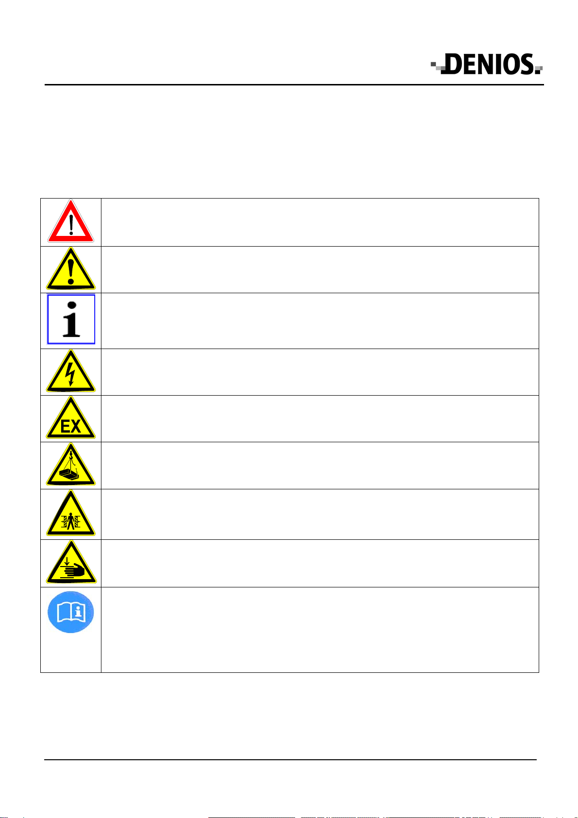
The following safety symbols are used in these operating instructions. Above all, these symbols are intended to
draw the attention of the reader to the adjacent safety instructions.
This symbol indicates that there are hazards to the life and health of persons.
The symbol indicates that there are hazards for the machine, material or environment.
This symbol identifies information provided to improve understanding of the product and correct
handling of the product.
This symbol warns of dangerous electrical voltage within the working area (e.g. electrical
distributors, terminal boxes, etc.)
This symbol warns of hazards caused by explosive atmospheres.
This symbol indicates suspended loads and their concomitant dangers.
This symbol indicates a possible risk of crushing
This symbol indicates a possible risk of crushing body parts (especially hands) by moving machine
parts or machine parts that are closing.
SEPARATE
INSTRUCTIO
NS
This point refers to additional operating instructions or regulations (enclosed or delivered
separately) required for operation or maintenance of accessories; these must be read and carefully
observed.
(safety instructions referring to these must always be observed).
BA_Batterie-Ladeschrank_002 page 4 May 2012
Keep these operating instructions stored in a safe place. They are for practical use and should be
available to the user at the location of the equipment.
These operating instructions apply to Batterie-Ladeschrank. It contains all the information needed
regarding correct startup, trouble-free operation, maintenance, removal from service and disposal.
The instructions in this user manual must be carefully followed and adhered to. The operating
personnel must be informed and sufficiently trained regarding the content of these operating
instructions.
No changes, extensions or modifications may be made to the product without the manufacturer's
written authorization.
National regulations and safety regulations have to be adhered to.
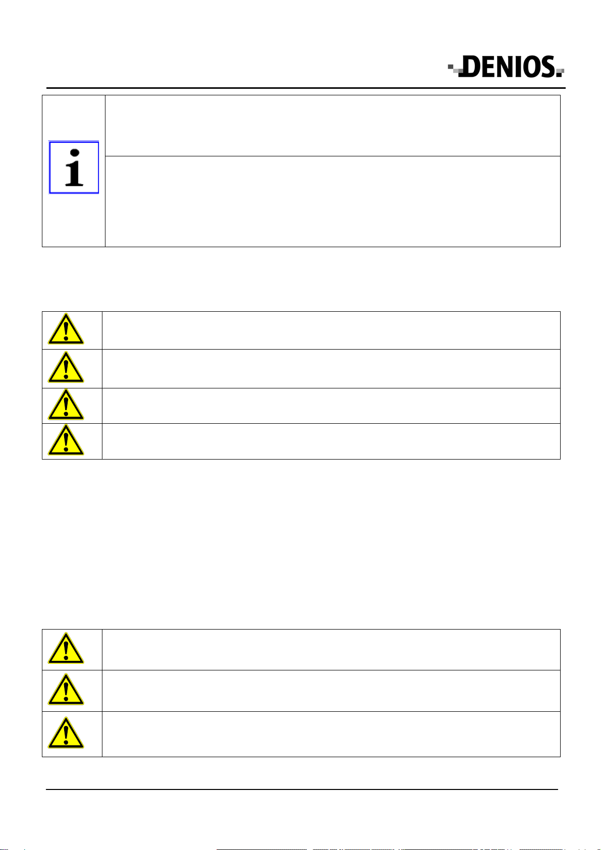
2 Safety instructions
Any damages to the battery charging cabinet must be remedied immediately in full observance of
the required safety measures.
Make sure the charging cable is disconnected before starting to charge!
Caution! Risk of short-circuit!
The device must be horizontal and be placed firmly on a suitable surface.
An obstruction of the air exhaust ducts must be checked before starting to charge!
Special safety instructions are contained in the following chapters.
3 Correct use in accordance to the instructions
The battery charging cabinet is used for safe charging of batteries from automobiles and lorries. Two different
battery chargers can be connected (chargers not supplied).
The operational temperature range is between -20°C and +40°C.
The charging cabinet must not be used as a storage facility.
The battery charging cabinet must not be transported with batteries installed in it! The charging
cabinet is not suitable for storing and transporting storing units.
The battery charging cabinet must never be exposed to direct sunlight or high temperatures for long
periods of time as otherwise this may lead to a reduction in inherent stability and strength in the
material.
BA_Batterie-Ladeschrank_002 page 5 May 2012
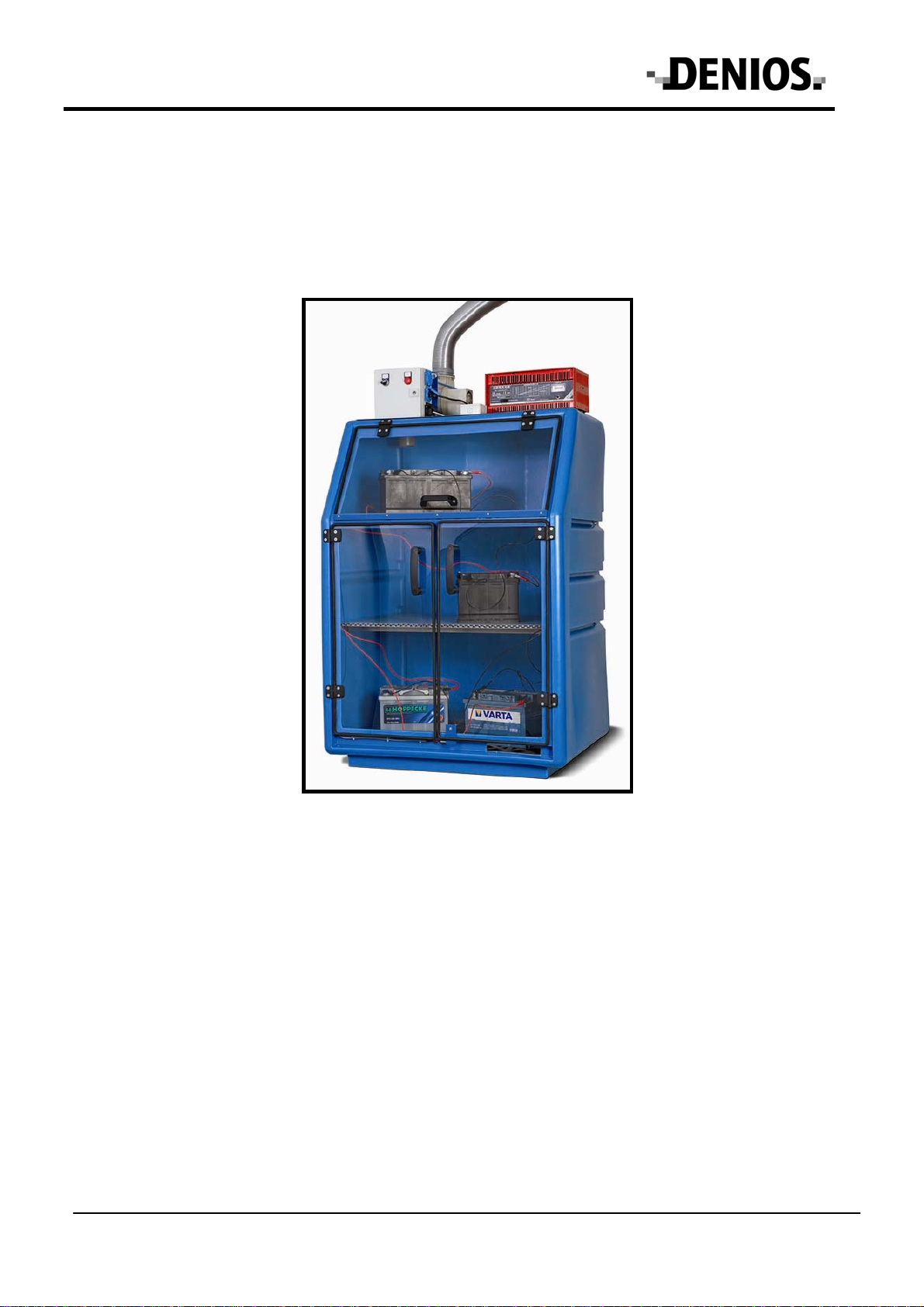
4 Product description
The design and configuration of the battery charging cabinet is based on the specifications of the German BGI
5017 "Charging facilities for vehicle batteries". The battery charging cabinet is fitted with the required control unit
for safe monitoring of the charging procedure. This control unit is positioned on the cabinet. The battery charging
cabinet is fitted with an automatic ventilation system with a follow-up time of 1 hour, as specified by the BGI 5017.
The batteries can only be charged when ventilation is switched on. The follow-up time of the fan is monitored by
the control unit
Compliant to BGI 5017 Chapter 3.3 "Planning aid for ventilation and explosion protection", the spaces/areas are
deemed to be non-explosive when the technical ventilation accords to the set requirements. No explosion-
protection is required for the technical ventilation when the fan is not within the gas-air current (min. device group
II, category 3G Ex).
The cabinet is fitted with transparent plexiglass doors so that the charging procedure can be easily monitored.
Additionally, there are connections for all commonly available battery chargers. The chargers can be placed on the
charging cabinet. There are connection terminals in the charging cabinet to simultaneously connect 2 batteries
each. There is an integrated sump with grate covering in the cabinet to catch any escaping liquids if necessary.
Additionally, the cabinet is comprised of a robust, acid and alkali proof polyethylene (PE) casing, coloured blue
and grey.
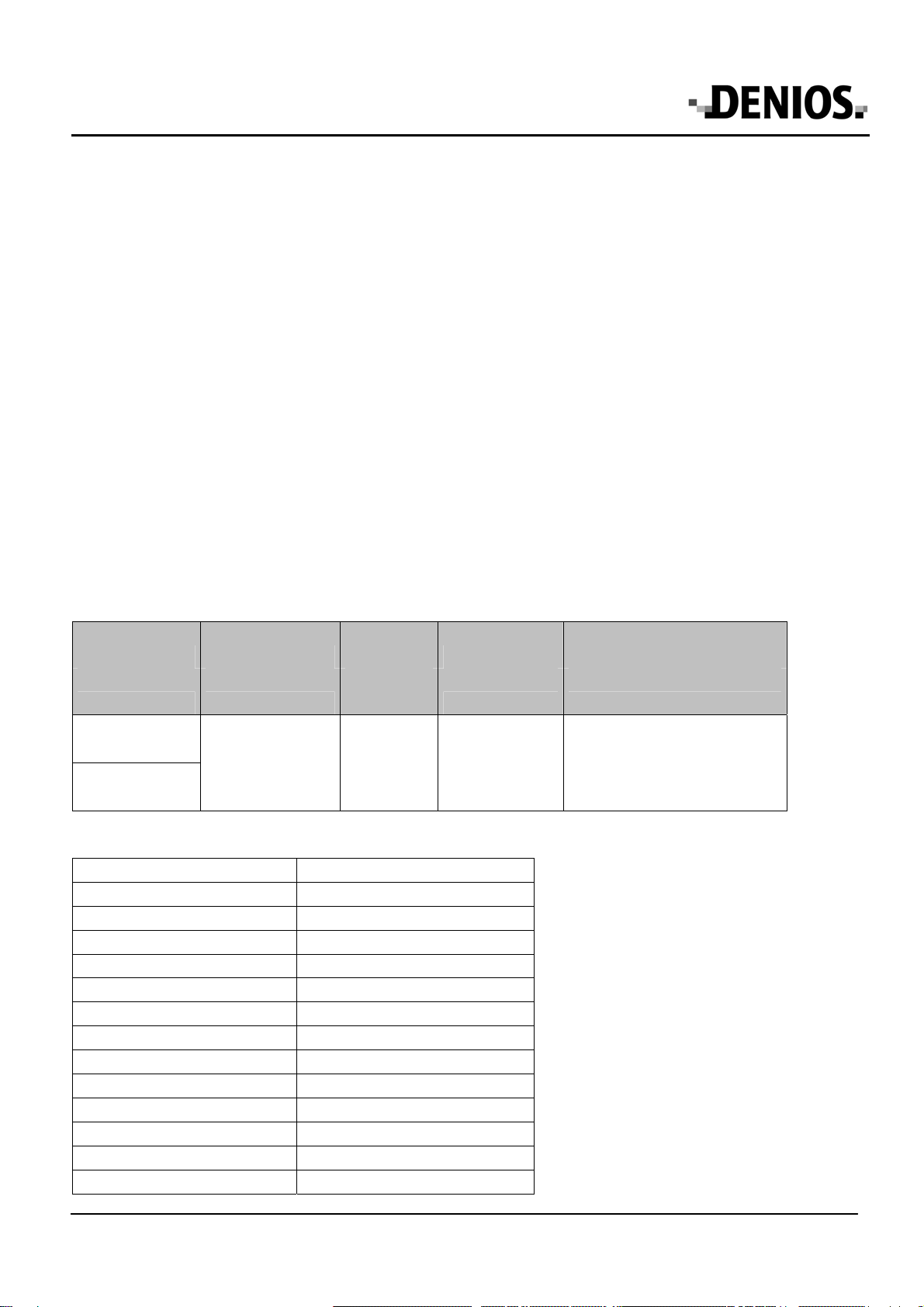
4.1 Technical Data
Type Dimensions Sump Bearing load bearing capacity of each
shelf
Art. No. w x d x h (mm) Capacities
(l) Grates (kg) (kg) UDL
PSR 8.8 in blue
186 933
PSR 8.8 in grey
186939
910 x 760 x 1300 25 400 80/50*
*wall-mounted
Weight 75 kg
Electrical connection 1/N/PE 230V~, protection class 1
Pre-fuse max. 10A
Power consumption max. 2kW
Fan
Type EP.VE.18610
Volumetric flow 0-140 m³/h
Total pressure 200-20 Pa
Voltage 230V
Current consumption 0.35A
ATEX-marking CE II 3 G T4
Differential pressure sensor
Type DBK-2G-20/300
ATEX-marking II2G EEx ia IIC T6
Other manuals for PolySafe-Depot PSR 8.8
2
Table of contents


