Bren-Tronics BTC-70844 Operation manual
850026 Rev B
OPERATION AND
SERVICE MANUAL
SOLDIER PORTABLE CHARGER
BTC-70844
USA Tel: (631) 499-5155 · Fax: (631) 499-5504
www.bren-tronics.com

WARNING
HIGH VOLTAGES ARE PRESENT IN THE
OPERATION OF THIS EQUIPMENT
Avoid contact with AC supply voltage connections during installation, operation or
maintenance of the battery charger.
CAUTION
ACID CONTAMINATES NICKEL-CADMIUM, LITHIUM-ION,
LITHIUM-POLYMER and NICKEL-METAL HYDRIDE BATTERIES
Every effort must be made to keep Nickel-Cadmium, Lithium-Ion, Lithium Polymer and
Nickel-Metal Hydride batteries as far away as possible from Lead-Acid batteries because
Lead-Acid batteries contain sulfuric acid. Do Not use the same tools and materials, such
as screwdrivers, wrenches, syringes, hydrometers, and gloves for both types of batteries.
Any trace of acid or acid fumes will permanently damage Nickel-Cadmium, Lithium-Ion,
Lithium Polymer and Nickel-Metal Hydride batteries on contact.
WARNING
NO SMOKING IS PERMITTED NEAR THE CHARGING STATION
Batteries can produce explosive gases during charging or discharge cycles. Never smoke
or allow open flames near the charging station.
TABLE OF CONTENTS
Para Pg Para Pg
CHAPTER 1 – INTRODUCTION
Scope............................................. 1-1 1-1
Technical Specifications ................ 1-2 1-2
Declaration of Conformity .............. 1-3 1-3
Accessories.................................... 1-4 1-4
Charge Cycle Description.............. 1-5 1-7
Sequential Charging Description ... 1-6 1-8
Upgrading Charger Software......... 1-7 1-9
CHAPTER 2 – OPERATING PROCEDURES
Panel Controls and Indicators........ 2-1 2-1
Preliminary Setup Procedures....... 2-2 2-3
Operating Procedures –
Charging Batteries.................... 2-3 2-4
Battery Revitalization and
Destorage ................................. 2-4 2-5
Battery Charger Cover Label ........ 2-5 2-7
Solid Red LED troubleshooting...... 2-6 2-8
Flashing Red LED troubleshooting 2-7 2-8
Operation in Extreme Environmental
Conditions................................. 2-8 2-9
Preparation for Movement.............. 2-9 2-9
Battery State-of-Charge Displays... 2-10 2-10
Battery Capacity Retention ............ 2-11 2-10
Battery Storage.............................. 2-12 2-11
CHAPTER 3 – MAINTENANCE INSTRUCTIONS
Introduction.................................... 3-1 3-1
Cleaning......................................... 3-2 3-1
Inspection....................................... 3-3 3-1
Basic Functional Test..................... 3-4 3-2
Simplified Operator
Troubleshooting Procedures..... 3-5 3-3
Warranty / repair Information ......... 3-6 3-5
Upgrade / Update Information........ 3-7 3-5

INTRODUCTION
1-1
CHAPTER 1
INTRODUCTION
1-1. SCOPE
The Soldier Portable Charger (P/N BTC-70844) is a CE –compliant, state-of-the-art,
high performance lightweight portable battery charger designed for field deployment or
shop usage. It provides fast reactivation of various rechargeable batteries. It is
capable of sequentially charging up to eight batteries completely unattended.
The Soldier Portable Charger is simple to use by design. Without any user
intervention, the Charger typically charges up to eight batteries, two at a time. Charge
times are substantially less for partially discharged batteries. The charge time for fully
depleted BB-2590/Us or BB-390B/U is less than 3 ½ hours. The charge time is
substantially less for partially discharged batteries. Charge times vary based on
battery type and the battery’s state of charge. The Charger automatically identifies the
specific battery type and provides the appropriate charge profile. Based on the
current operating environment, the Charger automatically customizes the charge
profile to provide the quickest charge in a safe manner. The charge status for each of
the batteries is conveyed to the user via easy-to-understand panel mounted LED
indicators (amber – CHARGE, green – READY and red – FAULT).
The Charger is universal by design. It can readily use either AC or DC input power –
whichever is most convenient for the user. The universal AC input fully allows 85-264
VAC and 47-440 Hz operation without any adjustment or user intervention.
Additionally, the DC input power permits a range of 20-33 VDC, standard on most
military vehicles.
The Charger is adaptive by design. It is microprocessor controlled and is presently
programmed to automatically charge over 50 different battery types as listed in the
Table 1. With the appropriate battery adapter, however, it can be readily
reprogrammed via RS232 software upgrade port in the field to charge a countless
number of additional battery types and chemistries including: Nickel Metal Hydride,
Nickel Cadmium, Lithium Ion, and Lithium Polymer. The Charger also provides a
Revitalization function for Nickel Cadmium batteries and a Destorage function for
Lithium Ion batteries.
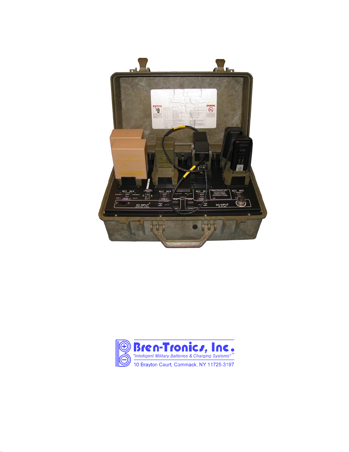
The battery charger components are housed in a durable, non-conductive ABS
equipment case, as shown in Figure 1. The assembled unit is watertight when the
gasketed cover is securely latched and the pressure equalization valve on the front of
the case (near the carrying handle) is closed.

INTRODUCTION
1-2
1-2. TECHNICAL SPECIFICATIONS
Dimensions ...........................……... 580mm W x 375mm D x 230mm H
Weight (less adapters and cables)….…...12.5kg
(with adapters and cables)……… 15kg
Power Requirements
AC operation .....................……… Automatic selection: 85 to 264 VAC, single-
phase, 47 to 440 Hz, 375 VA max, with 1.95m
detachable three-wire power cord. (Power draw
125 V=3 A)
DC operation ................... ……… 20-33 VDC, 15A, with 1.55m DC cable
assembly. (Power draw 24 V=12.5 A)
Charging Output Voltage.......……… Automatically selected for each battery type
Duty Cycle.............................…….... Continuous
Protective Features…………………. Resettable circuit breakers for AC (7A) and DC
(20A) Power sources
Operating Temp. Range …………… -20˚C to 50˚C
Storage Temp. Range ..........………. -40˚C to 70˚C
Case Material........................………. ABS (Acrylonitrile Butadiene Styrene)
Case Color............................………. Olive Drab #34088 per Fed-Std-595B
Shipment...............................………. No restrictions

INTRODUCTION
1-3
1-3. Declaration of Conformity
Manufacturer’s Name: Bren-Tronics, Inc.
Manufacturer’s Address: 10 Brayton Court
Commack, New York 11725
U.S.A.
Declares the Product:
Product Name: Solder Portable Charger
Model Number: BTC-70844
Conforms to the following Product Specifications:
Safety:
IEC 60950-1
EMC:
EN 55022:1998 Class B Conducted Emissions, 150kHz to
30MHz
EN 55022:1998 Class B Radiated Emissions, 30MHz to 1GHz
EN 61000-3-2:1995 Harmonics
EN 61000-3-3:1995 Flicker
IEC 61000-4-2:1995 Electrostatic Discharge
IEC 61000-4-3:1997 Radiated Immunity
IEC 61000-4-4:1995 FFT/Burst, Power Leads
IEC 61000-4-5:1995 Surge Immunity
IEC 61000-4-6:1996 Conducted Immunity
IEC 61000-4-11:1994 Voltage Dips and Interrupts
Supplementary Information:
I Dennis Rosenberg declare that the above product complies with the
requirements of the Low Voltage Directive 73/23/EEC and the EMC Directive
89/336/EEC and carries the CE marking accordingly.
Dennis Rosenberg/Quality Engineer

INTRODUCTION
1-4
1-4. ACCESSORIES
Table 1 shows the various batteries and appropriate adapter plates the Charger can
charge as of the writing of this document.
Table 2 shows the various power cables and other accessories.
Table 1 - Supported Batteries and Adapters
ADAPTER ADAPTER NSN BATTERY TYPE BATTERY NSN
BTA-70360 6130-01-555-7818 BB-4600 NiCd 6140-13-113-0171
BTA-70394 5940-01-427-9247 BB-503A/U NiCd 6140-01-419-8193
BTA-70395 (1) 5940-01-427-9183 BB-326/U
BB-516A/U NiMH
NiCd 6140-01-533-7674
6140-01-419-8191
BTA-70396 5940-01-427-9278 BB-2847A/U
BB-2847/U Li Ion
Li Ion 6140-01-493-8092
6140-01-419-8194
BTA-70443 5940-01-467-8813 BB-2600/U
BB-2600A/U Li Ion
Li Ion 6140-01-467-5853
6140-01-490-4311
BTA-70492A 5940-01-513-5662 BT-70477
BT-70492
BT-70492A
NiMH
Li Ion
Li Ion
6140-14-513-5369
6140-01-523-9840
6140-01-523-9840
BTA-70557 5940-01-467-5852 BB-557/U NiCd 6140-01-071-5070
BTA-70574 5940-01-483-6772 ICOM SI NiCd ---
BTA-70581 --- CSEL Li Ion 6140-01-534-3856
BTA-70581A 5940-01-544-3476 CSEL Li Ion 6140-01-534-3856
BTA-70582 --- ALI 124
ALI 142/BA-682A
BA-682B
BA-684A
NiCd
Li Ion
Li Ion
Li Ion
---
6140-14-328-2258
6140-14-561-1542
6140-14-529-5971
BTA-70589 6130-01-564-8116 ALI 116
ALI 124
ALI 142/BA-682A
ALI 143/BA-687A
ALI 243
BA-684A
BA-685A
BA-682B
ALI 147
ALI 247
NiCd
NiCd
Li Ion
Li Ion
Li Ion
Li Ion
Li Ion
Li Ion
Li Ion
Li Ion
---
---
6140-14-328-2258
6140-14-530-0061
6140-14-553-4062
6140-14-529-5971
6140-14-529-5973
6140-14-561-1542
---
---
BTA-70589A --- ALI 142/BA-682A
ALI 143/BA-687A
ALI 243
BA-684A
BA-685A
BA-682B
ALI 147
ALI 247
Li Ion
Li Ion
Li Ion
Li Ion
Li Ion
Li Ion
Li Ion
Li Ion
6140-14-328-2258
6140-14-530-0061
6140-14-553-4062
6140-14-529-5971
6140-14-529-5973
6140-14-561-1542
---
---
BTA-70598 --- BT-70598 Li Ion ---
BTA-70715 5940-01-573-9693 BT-70593
BT-70715 Li Ion
Li Ion ---
---
BTA-70721 6130-01-573-4962 BT-70721 Li Ion ---
BTA-70732 --- BT-70732 Li Ion ---
BTA-70737 --- BT-70737 Li Ion ---

INTRODUCTION
1-5
BTA-70740 --- BT-70740 Li Ion ---
BTA-70763 6130-01-555-7821 BN-2250 NiCd 6140-13-116-5482
BTA-70774 5940-01-573-9679 Motorola –
NNTN7032A
NTN9816A
NTN9815A
Li Ion
NiCd
NiCd
---
---
---
---
BTA-70807 5940-01-493-6750 BB-2800/U Li Ion 6140-01-490-5372
BTA-70808 5940-01-493-6388 BB-2588/U
BB-388/U Li Ion
NiMH 6140-01-493-7623
6140-01-490-4313
BTA-70810 5940-01-493-6751 THALES – MBITR Li Ion ---
BTA-70811 5940-01-493-7622 AA CELLS NiMH ---
BTA-70812 5940-01-492-7238 BB-2557/U
BB-557/U Li Ion
NiCd 6140-01-490-5387
6140-01-071-5070
BTA-70817 --- D CELLS NiMH ---
BTA-70834 5940-01-501-3312 BB-2590/U
BT-70791A
BT-70791E
BB-390B/U
BB-590/U
BT-70876
SAFT – SAI-2590
Li Ion
Li Ion
Li Ion
NiMH
NiCd
Li Ion
Li Ion
6140-01-490-4316
---
---
6140-01-490-4317
6140-01-063-3918 -
--
---
BTA-70899 --- BB-2590/U
BB-390B/U
BT-70791A
BT-70791E
BT-70899A
BT-70876
Saft – SAI-2590
Ultralife – UBI-2590
Li Ion
NiMH
Li Ion
Li Ion
Li Ion
Li Ion
Li Ion
Li Ion
6140-01-490-4316
6140-01-490-4317 -
--
---
---
---
---
---
BTA-70858 --- DRT 4453/4411 Li Ion ---
BTA-70406-3 --- BA-386 NiCd ---
BTA-70851 (1) --- Racal 931 NiCd ---
BTA-70852 --- PTR-349 NiCd ---
BTA-70853 --- Loral – RT1606 NiCd ---
BTA-70872 --- BB-NM10 NiCd ---
BTA-70868 --- LI-145
LI-80 Li Ion
Li Ion ---
---
BTA-70706-1 --- BB-2598 Li Ion ---
BTA-70406 --- BB-586 NiCd 6140-01-084-1460
BTA-70661 --- BT-70661 Li Ion ---
BTA-70685 --- ALKABAT NiCd ---
NOTES:
1) The Adapter BTA-70480/3 is not compatible with this charger.
2) This list was complete at the date of publication. Additional adapters may be available, but
may require updated software.

INTRODUCTION
1-6
Table 2 - Power Cables and Other Accessories
DESCRIPTION ORDER NUMBER PART NUMBER NSN
IEC AC POWER CORD US 591609 ---- ----
IEC AC POWER CORD EU 590233-3 ---- ----
IEC AC POWER CORD UK 590233-UK ---- ----
DC POWER CABLE BTA-70844-24 ---- ----
DC HUMMER CABLE BTA-70835 J-6362A/U 5940-01-501-6714
DC SPLITTER CABLE BTA-70816 CX-13560/G 5995-01-505-7883
BB-390/2590 SELF DISCHARGER BTF-70791 SDD2 6130-01-490-4310
Figure 1-4.1 DC ADAPTER CABLE
Figure 1-4.2 DC HUMMER CABLE
Figure 1-4.3 DC SPLITTER CABLE
For use with the DC Hummer cable
Figure 1-4.4 BB-390 /2590 SELF DISCHARGER

INTRODUCTION
1-7
1-5. CHARGE CYCLE DESCRIPTION
Each of the battery types that are capable of being charged by the Charger is
connected to the charger via their respective battery adapter (plate or cable). Each
adapter can charge two batteries simultaneously. The appropriate battery adapter is
installed on the control panel and serves as the electrical interface between the
batteries being charged and the charger circuits. The battery charger control circuits
constantly monitor the following battery conditions during the charge cycle, as
appropriate, to ensure that the battery is properly being charged:
a. Temperature (T)
b. Voltage (V)
c. Current (I)
d. Time (t)
e. Voltage change (ΔV)
f. Temperature rate of change (ΔT/Δt)
The charger operation during a typical charge sequence is automatic and the battery
charge status is displayed to the user by the panel LED indicators as follows:
a. Detection - The charger tries to detect a battery in an adapter. The CHARGE
LED (amber) blinks slowly during this process.
b. Pre-charge – The charger brings the battery voltage up to a safe level before
the rapid charge process begins. This step may take several minutes for a very
discharged battery. The CHARGE LED (amber) blinks rapidly during this
process.
c. Fast Charge – A timed fast charge cycle brings the battery to approximately
90% of full charge capacity. The CHARGE LED (amber) is lit solid during this
process.
d. Ready – The fast charge cycle is complete. The Battery may be removed and
used at this time. The READY LED (green) is lit steadily at this time.
e. Trickle / Top-off – When fast charge is complete, the charger will top off of the
battery to 100%. Each battery is charged for five minutes at a time. For Lithium
Ion and Lithium Polymer batteries the top-off cycle will stop after the battery is
100% charged. For all other types, the Trickle / Top-off cycle is repeated
indefinitely to keep the battery at 100% charge. Leaving the battery on the
charger will not harm the battery. The battery may be removed and used at this
time. The READY LED (green) blinks during this process.
The Battery may be removed and used at anytime during the charge cycle without
damage to the charger or battery. The state-of-charge indicator (SOC) will display the
battery condition. NOTE
After removing a battery from the charger, wait for the
corresponding battery status LED’s to turn off before installing a
new battery.

INTRODUCTION
1-8
1.6. SEQUENTIAL CHARGING CYCLE DESCRIPTION
The Charger is a dual-channel sequential charger. It automatically charges up to eight
batteries. The charge time depends on the battery type and state-of-charge.
Two independent charging channels, designated A and B, can charge one battery at a
time. Upon charge completion of the first battery, each channel sequentially charges
up to three additional batteries that are waiting in queue. Sequencing to the other
three Ports is performed completely automatic and requires no intervention by the
user. While the four batteries charged by the A channel are located at either the rear
or left side of each adapter Port (depending on the adapter type), the four batteries
charged by the B channel are located at either the front or right side of each adapter
Port. This is readily seen in Figure 1.6-1.
Figure 1.6-1 – Charger Typical Configuration
During the sequencing process, the channel spends only as much time as is
necessary to charge each battery to greater than 90% capacity. A partially charged
battery will charge quicker than a totally discharged battery. It then sequences, in
numerical order (Port 1 – Port 2 – Port 3 – Port 4 – Port 1 – Port 2, etc.), to the next
battery in queue. As the channel sequences through the four Ports and comes to a

INTRODUCTION
1-9
battery that has already been charged, it will attempt to Trickle or Top-off that battery
(if necessary) for approximately 5 minutes (10 minutes for dual section batteries like
the BB-390, BB-2590, BB-557, and BB-2557) and then continue onto the next Port.
This means batteries added later may charge first, depending ontheir position on the
charger. If certain batteries must be charged first, then this must be taken in to
account. When the charger moves to a position it will charge or top off the battery at
that position, as necessary. This allows batteries to be added or removed at anytime.
The charger automatically keeps track of the current state of each Port.
1.7 UPGRADING CHARGER SOFTWARE
The software in the charger is readily field upgradeable. By loading new software into
the charger, it is possible to alter its operation and add or change the charging profiles
for the batteries. Loading new software into the charge is accomplished via the use of
a standard RS232 interface of a personal computer (PC) running Windows 95™ or
higher. Utilizing special software running on the PC in conjunction with the boot
program resident within the charger, a two-way communication link is established and
the revised operational parameters and battery charge profiles can be loaded into the
charger. Specific instructions for upgrading the Charger software is provided with the
software upgrades.

OPERATION
2-1
CHAPTER 2
OPERATING PROCEDURES
2-1. CONTROLS AND INDICATORS
Battery charger panel components are described below and shown in Figure 2-1.
Item Function
AC ON/OFF power switch......Turns battery charger AC supply on or off.
AC CKT BREAKER................Turns power to the charger off in an overload condition.
Remove the overload condition and push to reset.
LOW VEH POWER LED........The Low Vehicle power indicator lights when external DC
power is too low to charge batteries. The charger will
stop charging batteries.
TEMP FAULT LED.................The Temperature Fault indicator lights when charger
temperature is too high (50°C) or too low (-20°C). The
charger will stop charging batteries.
DC ON/OFF power switch......Turns battery charger DC supply on or off. If both AC and
DC power are connected and both power switches are
on, then DC Power will be used by the charger.
DC CKT BREAKER................Turns power to the charger off in an overload condition.
Remove the overload condition and push to reset.
CHARGE LED........................The Amber LED lights steady while the associated
battery is being fast-charged. A slow blinking indication
means the charger is trying to find a battery at the select
position. A fast blinking indication means the charger is
precondition the battery before charging it.
READY LED...........................The Green LED indicates the associated battery is fully
charged and ready to be removed for use. Steady light
means the battery has completed fast charge. A blinking
indication means the battery is being topped off.
FAULT LED............................If the Red LED lights steady the associated battery, or
adapter plate, is defective or will not accept charge. A
blinking indication means the battery’s temperature
sensor or communication connection is not making
contact with the adapter.
AC INPUT Connector.............Input connection for AC cable assembly. (Provided)
DC INPUT Connector.............Input connection for DC cable assembly. (Optional)
Battery Adapter Port...............Provides interface connection for battery adapters.
RECONDITION Switch…….…Activates NiCad revitalization or Li-Ion destorage function
with battery in POS 1.
RECONDITION LED………….Lights amber during revitalization / destorage process.

OPERATION
2-2
Figure 2-1 – Charger Front Panel Components

OPERATION
2-3
2-2. PRELIMINARY SETUP PROCEDURES
Step 1. Place the unit on the work surface. Unscrew the pressure equalization valve
(near the carrying handle) in a counterclockwise direction about two full turns.
Unfasten latches and open cover.
Step 2. Set AC and DC power ON-OFF switches, to OFF position.
Step 3. The Cover may be removed by removing both hinge pins with pliers.
Step 4. For AC operation: Connect AC power cord from AC INPUT connector to
power source and set AC power ON-OFF switch to ON position. Observe
that POWER ON LED lights, fan operates, and all LED status indicators blink
in order (amber, green, then red) briefly when power is first applied.
Step 5. For DC operation: Connect DC cable from 24 VOLT DC INPUT connector to
DC power source (via NATO slave receptacle found in most military vehicles)
and set DC power ON-OFF switch ON position. Observe that POWER ON
LED lights, fan operates, and all LED status indicators blink in order (amber,
green, then red) briefly when power is first applied. Note that if both AC and
DC power are connected that DC power will be used if the DC power switch is
on.
Step 6. Observe that only the POWER ON LED is lit.
Step 7. Install appropriate battery adapter(s) on panel for battery types to be charged.
Install the Adapter(s) by placing the back of the adapter into the rear retainer
and rotating the adapter down until the front retainer clicks over it. Note the
alignment of the pins. The connector can only plug in one way. Do not force
it. Be sure that battery adapter and connector are fully seated. For Cable
type Adapters Line up the pins to the connector. 18 Pin Connectors will plug
in toward the right side on the charger. Again do not force the connector. All
battery adapters are interchangeable, only the battery connections are
different. The adapters may be mixed. It is not necessary to use only one
type of adapter at a time.
Step 8. Observe, after a short delay, the amber CHARGE LED’s blink for several
seconds at each installed adapter. This shows battery charger circuits are
initialized to the selected battery adapter and are ready to accept a battery (or
batteries) for charging. If all of the Indicators for a channel light at the same
time, the Adapter could not be recognized or the adapter is damaged. Insure
it is seated correctly. Verify that the charger software revision supports the
adapter.

OPERATION
2-4
2-3. OPERATING PROCEDURES – CHARGING BATTERIES
Step 1. With the appropriate battery adapter installed, insert the first battery to be
charged in the Port-1 Channel-A battery location. Insure the battery is fully
seated into the adapter. Observe that CHARGE LED (amber) for the
corresponding location is lit or blinking rapidly. The CHARGE LED for the B
battery location will continue to blink if it is searching for a battery on that
channel. If the FAULT LED (red) is lit, the battery or adapter may be
defective. Check by removing battery and adapter. Then reinstall adapter
and battery. If the FAULT LED again lights, go to the Trouble Shooting
section of this Guide.
Step 2. Install the next battery into the Port-1 Channel-B battery location.
Step 3. Install the rest of the batteries. The indicators for these batteries will not light
until the charger has finished the batteries in the preceding Port locations.
Step 4. After fast charging is complete, the CHARGE LED extinguishes and the
READY LED is lit. After the charger cycles through the batteries, it will top-
off batteries that have completed fast charge. The battery is slow-charged to
full capacity, as indicated by the blinking READY LED (green). The battery is
charged for five minutes at a time (10 minutes for dual section batteries) then
the charger will move on to the next battery. For Lithium type batteries, the
cycle will stop after the battery is 100% charged. For other types the cycle is
repeated indefinitely to keep the battery at 100% charge. As long as the
READY LED is lit (blinking or solid) the battery may be removed and returned
to service and another battery may be installed for charging.
NOTE
BB-390A/U and BB-390B/U batteries include two independent 12-volt
sections. A relay "clicking" may be heard from the battery adapter when
battery sections are switched. Other types of adapters may also contain
relays and click intermittently during normal operation.
NOTE
Battery charger power may be left ON while batteries and/or adapters are
removed or replaced. Batteries maybe left on the charger for long periods
oftime without damaging the batteries or charger. This is true whether the
charger is on or off.
CAUTION
To avoid damage to the adapter or SPC front panel connectors, always
remove the adapter by grasping the front section finger-grips firmly with
one hand while moving the front retainer back with the other. Lift the front
of the adapter straight up from the panel. DO NOT attempt to remove the
adapter by pulling upward from the rear.

OPERATION
2-5
2-4. BATTERY REVITALIZATION AND DESTORAGE
The procedures outlined below describe the means of invoking the Revitalization and
Destorage functions of the Charger as well as the sequence of operations the charger
will execute to perform the commanded tasks. NiCad and NiMh Batteries are always
Revitalized. Li-Ion batteries are always destored. The charger will decide what to do
based on the battery’s chemistry.
a. NiCad Revitalization
Revitalization exists only on Position 1 and is available for both the A and B channels of
the Charger. Due to the increased power dissipation from discharging the batteries, this
function will not operate above 40º C. The following procedure is used to invoke the
Revitalization process:
1. Plug the Adapter into POS 1.
2. Power up the Charger.
3. Once the Adapter is recognized (the BAT LED’s blink Amber in Position 1), press
the RECONDITION SW pushbutton for the A or B channel; the RECON LED will
light Amber for the corresponding channel.
4. Plug the battery into the activated channel.
5. Revitalization will commence upon recognition of the battery.
Autonomously, the Charger will perform the following revitalization sequence:
1. Check the thermistor; if the temperature is above 40º C it will not proceed.
2. Discharge the battery without a capacity measurement.
3. Fully charge the battery.
4. Discharge the battery and calculate the capacity.
5. Fully charge the battery.
6. If the capacity in step 4 is greater than or equal to 80% of the battery
specification, the BAT LED turns Green, the RECON LED remains lit and
process is complete.
7. If the capacity in step 4 is less than 80%, repeat step 4 and 5 a second time. If
after the second cycle the capacity is less than 70% of the battery specification,
the BAT LED turns Red, the RECON LED remains lit and the process is
complete.
b. Li-Ion Destorage
Destorage exists only on Position 1 and is available for both the A and B channels of
the Charger. Due to the increased power dissipation from discharging the batteries, this
function will not operate above 40º C. The following procedure is used to invoke the
Destorage process:
1. Plug the Adapter into POS 1.
2. Power up the Charger.

OPERATION
2-6
3. Once the Adapter is recognized (the BAT LED’s blink Amber in Position 1), press
the RECONDITION SW pushbutton for the A or B channel; the RECON LED will
light Amber for the corresponding channel.
4. Plug the battery into the activated channel.
5. Destorage will commence upon recognition of the battery.
Autonomously, the Charger will perform the following Destorage sequence:
1. Check the thermistor; if the temperature is above 40º C it will not proceed.
2. Fully discharge the battery.
3. Fully charge the battery.
4. Discharge 55% of the specified capacity from the battery.
5. The BAT LED turns Green, the RECON LED remains lit and process is complete.

OPERATION
2-7
2-5. BATTERY CHARGER COVER LABEL
Shown below are the instructions contained on the "SHORT FORM - OPERATING PROCEDURE" label, attached inside
the Charger cover.
LED INDICATIONS FOR EACH BATTERY
S = STEADY, F = FLASHING, RF = RAPID FLASHING
YELLOW GREEN RED RECON MEANING REMARKS
F F F Charger start up. All lights blink by color when charger is turned ON.
Power on, no adapter. Adapter(s) must be installed.
F Power on, adapter present, no battery present. Install battery(s) on to adapter.
RF Battery identification and prequalification. Battery identification and prequalification is in progress - wait.
S Battery is fast charging.
F Battery is being topped off. Battery is ready to use. Remove it when ready.
S Battery charging complete. Battery is ready to use. Remove it when ready.
S or F S or F F Charging or identification contacts damaged or dirty. Clean battery contacts. Check adapter pins. Clean, repair or
replace as necessary.
S Faulty battery. Remove battery and replace a the same positon for one
additional charge cycle. See “Red LED Troubleshooting” in
user manual.
S Recondition / Destore Enabled. Cycle will begin when charger get to the battery.
S S Recondition / Destore cycle in progress
S Recondition / Destore cycle complete. Recondition / Destore cycle complete. Remove it when ready.
S S S Recondition / Destore has failed. Battery may be defective.
F Temperature > 104° F / 40°C recondition not allowed. Reduce Ambient temperature and restart recondition cycle.
S S S Damaged or Unknown adapter. Replace Adapter.
If a Software update is required visit web site for details.

OPERATION
2-8
2-6. SOLID RED LED TROUBLE SHOOTING
1. Remove battery and inspect all contacts. Clean if nessasary. Then, reinstall at
same location for another charge cycle. Note battery and adapter location for
laterreview.
2. If charge indications go "red" again at the same location remove battery and do
the following:
a. If the battery was in storage see para 2-14.
b. Check battery: older than 3 yrs? Maybe ready for disposal. Discharge &
recharge, IF RED AGAIN?
c. Check warranty instructions on battery. If not covered or no instructions,
dispose of.
d. Note success/failure of future battery charges at this location. More
"RED" lights? Change adapter.
2-7. FLASHING RED LED TROUBLE SHOOTING
1. This condition is telling you that some of the battery contacts are not connecting
to the charger.
a. For BB-390 thermal contacts not making contact with the charger.
b. For BB-2800, BB-2600 and other batteries the communication pin(s) are
not making contact with the charger.
2. To minimize this issue before you first start using the charger: Ensure….
a. The contacts are clean on the battery.
b. The adapter contact pins are in place and retain their spring action: Check
by pushing down the pins and releasing.
3. You can still charge Batteries with thermal / communication pins missing or
damaged, it will just take longer, and may not fully charge in one cycle.
4. If the flashing "red" condition continues after this check, mark location of
condition and battery affected.
a. You can pull batteries and clean thermal contacts on the battery.
b. Check adapters again. Mark for future review, if a continuing problem at
this location: change adapter.

OPERATION
2-9
2-8. OPERATION IN EXTREME ENVIRONMENTAL CONDITIONS
Observe these precautions when the Charger is operated in areas where severe
climatic conditions may exist:
a. Operation in Arctic Climates. The battery charger is designed to function in
temperature extremes as low as -4°F (-20°C.). The following precautions should be
observed:(1) Handle equipment carefully. The plastic components may become more
brittle.
(2) Keep equipment clean and dry.
(3) Prevent ice from forming on the Charger and batteries. Ice formations
may prevent proper electrical connections. Melting ice may cause water
to enter the charger.
b. Operation in Desert Climates. The Charger is designed to operate in
temperature extremes as high as 122°F (50°C) and the dryness associated with a
desert environment. Sand and dust accumulation on and in the charger may cause
poor electrical connections and reduce the cooling effectiveness of the charger. Follow
proper cleaning and maintenance guidelines to assure proper operation. When not in
use, be sure that cover is fully latched and pressure relief valve is fully closed (in a
clockwise direction).
c. Operation in Salt Spray. Keep equipment clean and dry at all times and
immediately wipe salt spray from exposed surfaces, cables and connectors. When not
in use, be sure that cover is fully latched and pressure relief valve is fully closed (in a
clockwise direction).
NOTE
Battery charge acceptancevarieswith ambienttemperatureconditions. At
temperatureslower than 32°F (0°C)orhigher than 104°F (40°C)itmaybe
necessary to initiate two complete charging cycles to secure a fully
charged battery.
2-9. PREPARATION FOR MOVEMENT
a. Set both AC and DC POWER switches to OFF.
b. Remove any installed batteries.
c. Disconnect and coil AC power cable.
d. Remove the DC Power cable and pack separately.
e. Replace Charger cover if it was removed by reinstalling the hinge pins.
f. Close cover and secure with latches.
g. Close pressure equalization valve on front of unit by turning fully clockwise.
Table of contents
Other Bren-Tronics Batteries Charger manuals


Popular Batteries Charger manuals by other brands


Bebob
Bebob VS4-RL user manual

VOLTCRAFT
VOLTCRAFT UFC-8 operating instructions

Ericsson GE
Ericsson GE 19B801507P1 Maintenance manual

Hamlet
Hamlet XPWNB100PDU user manual

Global Technology
Global Technology Six-bay Multi-chemistry Charger Operation manual

Mammooth
Mammooth M.DC.T.CH.20.40.2.4 instruction manual