brent Corner Auger 1080 Installation and maintenance instructions
PART NO. 280900
OPERATOR’S MANUAL
PARTS CATALOG
MODELS
1080 & 880
Corner Auger
TM
GRAIN CART
Model 1080 Beginning With Serial Number B20920100
Model 880 Beginning With Serial Number B20910100

2
Introduction
WARNING! CALIFORNIA PROPOSITION 65 WARNING: THIS MACHINE MAY CONTAIN MINERAL
OILS KNOWN TO THE STATE OF CALIFORNIA TO CAUSE CANCER, BIRTH DEFECTS, AND
OTHER REPRODUCTIVE HARM.
INTRODUCTION
NOTE: The information, specifications, and illustrations in the manual are on the basis of
information available at the time it was written. Due to continuing improvements in the de-
sign and manufacture of Brent products, all specifications and information contained herein
are subject to change without notice. Obtain the complete and most current information
before starting any job.
Foreword
This symbol identifies important safety messages. When you see it, read the message
that follows and be alert to the possibility of personal injury.
Remember, safety instructions stated in this manual are for your protection. Read them carefully
and follow them closely when working around or using this machine.
Read and study this manual completely before attempting to operate this implement. Take this
manual to the field for handy reference when operating, adjusting or servicing your machine.
When referenced, “Right-Hand” (RH) and “Left-Hand” (LH) side of the machine are
determined by standing behind the machine and facing in the direction of travel.
Revised 011906-7

3
Introduction
Product Identification
When ordering parts or when requesting further information or assistance, always give the fol-
lowing information:
- Machine name
- Model number
- Serial number
Please fill out and retain this portion for your records. The serial number decal is located at
the left front corner of your grain cart.
Purchase date Model Serial no.’s
Dealer City
Dealer Contact Phone
Revised 041608-15
Wheel bolts tightened (recheck after initial
use)
Tire pressures checked
Hardware tightened
Machine lubricated
Safety and operating procedures reviewed
Field adjustment information reviewed
Lubrication procedures reviewed
Warranty information reviewed
Hydraulic hoses properly routed/fittings tight
PRE-OPERATION CHECKLIST

4
Introduction
TABLE OF CONTENTS
SECTION I - SAFETY
GENERAL HAZARD INFORMATION .................1-2
SAFETY DECALS...............................................1-3
FOLLOW SAFETY INSTRUCTIONS..................1-4
OPERATING.......................................................1-4
TRANSPORTING................................................1-5
SERVICING/MAINTENANCE..............................1-5
DRIVELINE SAFETY..........................................1-6
PREPARING FOR EMERGENCIES...................1-7
WEARING PROTECTIVE EQUIPMENT.............1-7
SECTION II - OPERATION
PREPARING TRACTOR..................................... 2-2
PREPARING CART
INSPECTION ............................................... 2-2
LUBRICATION ............................................. 2-2
HITCHING TO TRACTOR
DRAWBAR CONNECTION.......................... 2-3
HITCH SETTINGS....................................... 2-3
JACK............................................................ 2-3
TRANSPORT CHAIN CONNECTION.......... 2-3
HYDRAULIC CONNECTIONS..................... 2-4
ELECTRICAL CONNECTIONS.................... 2-5
LIGHT MODULE.......................................... 2-5
LAMP BRACKET......................................... 2-5
TOWING............................................................. 2-6
AUGER OPERATION
COUPLING PTO DRIVE SHAFT................. 2-6
CHAINS ....................................................... 2-7
SHEAR BOLT/FRICTION CLUTCHES ........ 2-7
PTO-DRIVEN AUGER ................................. 2-8
SCALE (OPTIONAL) .......................................... 2-9
HYDRAULIC DRIVE (OPTIONAL).................... 2-15
TARP (OPTIONAL) (PRIOR TO SERIAL #B24060100).. 2-16
TARP (OPTIONAL) (SERIAL #B24060100 & UP)........ 2-17
OPTIONAL TRACK
OPERATING PROCEDURES.................... 2-18
DAILY OPERATING CHECKLIST.............. 2-18
TRACK ALIGNMENT................................. 2-19
WHEEL ALIGNMENT................................. 2-21
SECTION III - MAINTENANCE
LUBRICATION
CART ........................................................3-2
TRACK OPTION...........................................3-3
TRACK SYSTEM MAINTENANCE......................3-4
TRACK TENSION.........................................3-4
CHECKING TRACK TENSION..............3-4
ADJUSTING TRACK TENSION.............3-4
TRACK ALIGNMENT...........................................3-5
CHECKING TRACK ALIGNMENT................3-5
ADJUSTING TRACK ALIGNMENT...............3-6
IDLER WHEEL REPLACEMENT.........................3-7
MID-ROLLER REMOVAL.....................................3-8
IDLER WHEEL HUB ASSEMBLY........................3-9
MID-ROLLER ASSEMBLY.................................3-10
MID-ROLLER INSTALLATION...........................3-10
TRACK HUB BEARING SETTING ..................3-12
IDLER HUB ................................................3-12
MID-ROLLER HUB.....................................3-12
HITCH SETTINGS
HEIGHT ADJUSTMENTS ...........................3-13
HITCH BUSHINGS.....................................3-13
WHEEL NUT TORQUE .....................................3-14
TIRE PRESSURE & WARRANTY.....................3-14
AUGER DRIVE LINE
BEARINGS..................................................3-15
GEAR BOX.................................................3-15
SEASONAL STORAGE .....................................3-15
PAGE
AUGER SYSTEM
LOWER AUGER.........................................3-16
UPPER AUGER..........................................3-17
REMOVAL OF AUGER LINER..........................3-18
ASSEMBLY OF TUBE LINER...........................3-18
VERIFY PTO SHAFT LENGTH.........................3-19
PTO SHAFT & CLUTCH...................................3-22
PTO QUICK DISCONNECT..............................3-25
PTO CLUTCH ..................................................3-26
SCALE TROUBLE SHOOTING.........................3-27
SCALE CALIBRATION & SET-UP.....................3-28
TARP TROUBLE SHOOTING ...........................3-31
INSPECTION & MAINTENTANCE..............3-31
TRACK TROUBLE SHOOTING.........................3-31
ELECTRICAL SYSTEM SCHEMATIC ...............3-32
HYDRAULIC SYSTEM SCHEMATIC.................3-33
TORQUE CHART
HARDWARE ...............................................3-34
HYDRAULIC FITTINGS..............................3-35
WHEEL TORQUE REQUIREMENTS .........3-35
Revised 041608-15

5
Introduction
SECTION IV - SET-UP
BASIC CART SET-UP
FOLDING SIDE EXTENSION SET-UP........4-2
LADDER ...................................................... 4-2
LAMP SET-UP............................................. 4-2
DIRECTIONAL SPOUT INSTALLATION...... 4-3
ADJUSTABLE AXLE (OPTIONAL)............... 4-4
TIRE PRESSURE........................................ 4-4
DRIVELINE STORAGE................................ 4-4
SCALE KIT INSTALLATION
HITCH ASSEMBLY...................................... 4-5
JUNCTION BOX.......................................... 4-5
LOAD CELL INSTALLATION....................... 4-5
INDICATOR MOUNTING............................. 4-6
ELECTRICAL CONNECTION...................... 4-6
LOAD CELL CONNECTION........................ 4-7
TARP INSTALLATION (PRIOR TO SERIAL #B24060100)
END CAPS & BOWS .................................. 4-8
RIDGE STRAP, TARP, TUBES.................... 4-9
ROLL TUBE SPOOLS............................... 4-10
ROLL TUBE CABLES & RATCHETS .......4-11
HAND CRANK........................................... 4-13
CABLE TENSION...................................... 4-13
TARP INSTALLATION (SERIAL #B24060100 & UP)
END CAPS & BOWS ................................ 4-14
RIDGE STRAP, TARP, TUBES.................. 4-15
HAND CRANK........................................... 4-17
CABLE TENSION...................................... 4-18
HYDRAULIC DRIVE INSTALLATION............... 4-19
TABLE OF CONTENTS
SECTION V - PARTS
FINAL ASSEMBLY...............................................5-2
HITCH..................................................................5-4
AXLE - RIGID 880/1080 ....................................5-5
AXLE - ADJUSTABLE 880/1080.........................5-6
AXLE MOUNTING...............................................5-7
HUB - SINGLE WHEELS....................................5-8
HUB - DUAL WHEELS........................................5-9
WHEELS & TIRES ............................................5-10
DECALS.............................................................5-11
SIDE BOARDS - 880........................................5-12
SIDE BOARDS - 1080......................................5-13
ELECTRICAL.....................................................5-14
DRIVE COMPONENTS .....................................5-17
AUGER..............................................................5-18
FOLD INDICATOR.............................................5-20
CLEANOUT DOOR............................................5-21
FLOW DOOR SEALS........................................5-22
AUGER CYLINDER...........................................5-23
HYDRAULICS....................................................5-24
DIRECTIONAL SPOUT......................................5-26
PTO ASSEMBLY...........................................5-28/29
PTO CLUTCH...............................................5-30/31
45OGEAR BOX.................................................5-32
DRIVE LINE U-JOINT ASSEMBLY ...................5-33
SCALE UNIT - 880/1080 (OPTIONAL).............5-34
TARP - 880/1080 (OPTIONAL)
PRIOR TO SERIAL #B24060100...............5-36
SERIAL #B24060100 & UP.......................5-38
HYDRAULIC DRIVE (OPTIONAL).................... 5-40
TRACK ASSEMBLY & AXLE (OPT)................. 5-41
TRACK ROLLER FRAME ............................... 5-42
TRACK MID-ROLLER ASSY ........................... 5-43
TRACK HUB & SPINDLE ............................... 5-44
VIDEO SYSTEM OPTION................................ 5-45

6
Introduction
ACCIDENTS
CAN BE PREVENTED
WITH YOUR HELP!
No accident-prevention program can be successful without the whole-hearted cooperation of the
person who is directly responsible for the operation of the equipment.
A large number of accidents can be prevented only by the operator anticipating the result be-
fore the accident is caused and doing something about it. No power-driven equipment, whether it be
transportation or processing, whether it be on the highway, in the harvest field, or in the industrial plant,
can be safer than the person who is at the controls. If accidents are to be prevented--and they can be
prevented--it will be done by the operators who accept the full measure of their responsibility.
It is true that the designer, the manufacturer, and the safety engineer can help; and they will
help, but their combined efforts can be wiped out by a single careless act of the operator.
It is said that, "the best kind of a safety device is a careful operator." We, at Unverferth Mfg.
Co., Inc. ask that you be that kind of operator.
SAFETY PRECAUTIONS
Read this manual carefully before operating.
Never enter the grain cart while the auger is running.
Make sure PTO guard is kept in place.
Never allow anyone on the unit while moving through the field.
Be careful when moving unit near electrical lines with discharge auger up.
Never tow a loaded unit more than 8 m.p.h. or on a road.
Never exceed the maximum recommended hitch pin size which allows for uneven terrain.
Make use of night-time lighting provided on your new cart.
Use caution when unloading on the go, while moving through gullies, wash-
outs, and uneven terrain.
Always check behind you before backing up.
Counter-weight your tractor front end.
Be careful on steep slopes. A loaded grain cart is hard to stop.
Do not fold or unfold auger while moving.
When auger is not in use, be sure to fold to the rest position.
Never unhook a grain cart while it is being loaded.
Turn the tractor power off and remove the key from the ignition before servicing the attached
implement.
Tow only an empty cart on-road and have a rated transport chain attached.
Revised 060807-12

1-1
Safety
SECTION I
SAFETY
GENERAL HAZARD INFORMATION ............. 1-2
SAFETY DECALS ..........................................1-3
SAFETY.......................................................... 1-4
FOLLOW SAFETY INSTRUCTIONS......... 1-4
OPERATING.............................................. 1-4
TRANSPORTING....................................... 1-5
SERVICING/MAINTENANCE.....................1-5
DRIVELINE SAFETY.................................1-6
PREPARING FOR EMERGENCIES.......... 1-7
WEARING PROTECTIVE EQUIPMENT....1-7
Revised 061207-12

1-2
Safety
REMEMBER:
THINK SAFETY
A CAREFUL OPERATOR IS THE
BEST INSURANCE AGAINST AN
ACCIDENT!
GENERAL HAZARD INFORMATION
Most accidents involving product operation, maintenance and repair are caused by failure to observe
basic safety rules or precautions. An accident can often be avoided by recognizing potentially hazard-
ous situations before an accident occurs. A person must be alert to potential hazards. This person
should also have the necessary training, skills and tools to perform these functions properly.
Improper operation, maintenance or repair of this machine can be
dangerous and could result in injury or death. Do not operate or perform
any maintenance or repair on this machine until you have read and
understood all applicable safety, operation, maintenance, or repair
information.
NOTE! This SAFETY ALERT SYMBOL is found throughout this manual. Signal words are used
to alert users of potential hazards and the severity of these hazards.
SIGNAL WORDS:
DANGER:
INDICATESANEXTREMELYHAZARDOUSSITUATIONORAC-
TION THAT WILL RESULT IN SERIOUS INJURY OR DEATH.
WARNING: INDICATES A HAZARDOUS SITUATION OR ACTION THAT
COULD RESULT IN SERIOUS INJURY OR DEATH.
CAUTION: INDICATESAN UNSAFE SITUATION ORACTION THAT MAY
RESULT IN PERSONAL INJURY.
IMPORTANT: Is used for instructions on operating, adjusting, or servicing a
machine.
This symbol means:
ATTENTION!
BECOME ALERT!
YOUR SAFETY IS INVOLVED!
Revised 060807-12

1-3
Safety
251927
Revised 060807-12
SAFETY DECALS
WARNING
Replace lost, damaged, painted, or unreadable decals immediately. If parts that have de-
cals are replaced, also make sure to install new decals. These decals inform and remind
the operator with operational information and safety messages.
1-4
Safety
OPERATING
Do not stand between the cart and tractor when
hitching. Always engage parking brake and stop
engine before inserting hitch pin.
SAFETY
FOLLOW SAFETY
INSTRUCTIONS
Read and understand this operator's manual and
the tractor operator's manual before operating.
Do not wear loose fitting clothes, as they may
catch in moving parts.
Do not allow anyone to ride on the equipment.
Make sure everyone is clear before operating
machine or tractor.
Never play in or on the grain. Flowing grain
traps and suffocates victim in seconds.
Never attempt to operate implement unless you
are in driver’s seat.
Escaping fluid under pressure can penetrate the
skin causing serious injury. Relieve pressure
before disconnecting hydraulic lines or servicing
hydraulic system. See tractor operator's manual
for procedure to relieve pressure.
Use a piece of cardboard or wood to detect
leaks of hydraulic fluid under pressure. Correct
hydraulic leaks immediately.
Do not bend or strike high-pressure lines. Do
not install bent or damaged tubes or hoses.
Repair all oil leaks. Leaks can cause fires,
personal injury, and environmental damage.
Route hoses and lines carefully to prevent pre-
mature failure due to kinking and rubbing against
other parts. Make sure that all clamps, guards
and shields are installed correctly.
IF INJURED BY ESCAPING HYDRAULIC OIL,
SEE A DOCTOR AT ONCE, SERIOUS IN-
FECTION OR REACTION CAN DEVELOP IF
PROPER TREATMENT IS NOT ADMINISTERED
IMMEDIATELY.
Secure drawbar pin with safety lock and lock
tractor drawbar in fixed position.
All machinery should be operated only by trained
and authorized personnel.
To prevent machine damage, use only attach-
ments approved by the manufacturer.
Always shut tractor engine and hydraulic power
unit engine off and remove the keys from igni-
tion before servicing implements.
1-5
Safety
SAFETY
Be sure the tires are inflated to the recom-
mended pressure.
Always make certain everyone and everything
is clear of the machine before beginning op-
eration.
DO NOT allow ANYONE to enter or climb on
the Grain Cart during operation. If entry is
necessary, be sure P.T.O. is disengaged, chute
door is closed, tractor engine is off, the igni-
tion key removed and tractor brakes are locked
before entry.
TRANSPORTING
Comply with state and local laws governing
highway safety when moving machinery on
public roadways.
Use accessory lighting or warning lights when
transporting at night to adequately warn opera-
tors of other vehicles.
Regulate speed to road conditions. Maximum
speed should never exceed 20 m.p.h.
Make sure that SMV emblem, reflectors, and
lights are visible to approaching traffic.
Avoid contact with overhead utility lines. Electri-
cal shock can cause serious injury or death.
SERVICING/
MAINTENANCE
To avoid possible injury, lower the implement
to the ground before servicing.
Properly ballast the tractor before operating.
(See tractor operator’s manual.)
Regulate speed to field conditions, maintain
complete control at all times.
Use extreme care when operating close to
ditches, fences, or on hillsides.
Do not dismount from a moving tractor.
Check box for any debris or excess grain be-
fore each use.
Be sure that all safety shields are in place and
securely latched.
Do not work under an unsupported implement.
Use blocks or jackstands with a load rating equal
to or greater than the weight of the implement
for adequate support.
Do not grease or oil the equipment while in
operation.
Work in a clean and dry environment.
Before attempting any repairs you are unfamiliar
with, consult your local dealer.
When working around the cart, be careful not
to be cut by sharp edges.

1-6
Safety
DRIVELINE SAFETY
Do not allow children near equipment that is
running or engaged.
Keep all guards and shields in good condition
and properly installed at all times.
Avoid personal attire such as loose fitting cloth-
ing, shoestrings, drawstrings, pants cuffs, long
hair, etc. that can be come entangled in a
rotating driveline.
Do not exceed 1000 rpm PTO speed.
Disengage the PTO, stop the tractor engine, and
remove key from ignition before making inspec-
tions, or performing maintenance and repairs.
Inspect the driveline, quick disconnect, overload
shear-bolt limiter or clutch, and shielding often.
Repair immediately. Use replacement parts and
attaching hardware equivalent to the original
equipment. Do not alter the original design of
the driveline.
Avoid excessively long hardware or exposed
and protruding parts which can snag and cause
entanglement.
Lubricate the driveline as recommended in the
MAINTENANCE section.
Keep hoses, wiring, ropes, etc. from dangling
too close to the driveline.
Install driveline and shields according to rec-
ommended lengths and attaching methods with
recommended hardware. The driveline shield
should rotate independently a full rotation and
telescope freely. The retaining chain must be
secured to the implement safety shield.
Attach offset drawbar hitch end in the down
position and use a recommended hitch pin with
a low head so that no interference occurs with
driveline during operation on uneven or terraced
terrain.
Be careful not to hit the driveline with tractor
tires when turning.
Due to variances in tractor drawbar design and
operating position, it is critical that proper
extended and collapsed lengths of the tele-
scoping PTO shaft be verified before first
operation. If the extended length of the PTO
shaft is not sufficient, it may become uncoupled
in operation and cause serious injury or death
from contact with uncontrolled flailing of PTO
shaft assembly components. Refer to the MAIN-
TENANCE section of this manual for detailed
instructions.
254917

1-7
Safety
PREPARING FOR
EMERGENCIES
Keep a first aid kit and fire extinguisher nearby.
Keep emergency numbers for fire, rescue, and
poison control personnel near the phone.
WEARING PROTECTIVE
EQUIPMENT
Wear clothing and personal protective equipment
appropriate for the job.
Wear steel-toed shoes when operating.
Wear hearing protection when exposed to loud
noises.
Do not wear additional hearing impairing devices
such as radio headphones, etc.

1-8
NOTES

2-1
Operation
SECTION II
OPERATION
PAGE
PREPARING TRACTOR...........................2-2
PREPARING CART
INSPECTION.......................................2-2
LUBRICATION.....................................2-2
HITCHING TO TRACTOR
DRAWBAR CONNECTION..................2-3
HITCH SETTINGS...............................2-3
JACK USAGE......................................2-3
TRANSPORT CHAIN CONNECTION..2-3
HYDRAULIC CONNECTIONS ............2-4
ELECTRICAL CONNECTIONS............2-5
OPTIONAL LIGHT MODULE...............2-5
LAMP BRACKET ADJUSTMENT........2-5
TOWING...................................................2-6
AUGER OPERATION
COUPLING PTO DRIVE SHAFT ........2-6
CHAINS...............................................2-7
SHEAR BOLT/FRICTION CLUTCHES 2-7
PTO-DRIVEN AUGER.........................2-8
SCALE......................................................2-9
HYDRAULICALLY DRIVEN AUGER.......2-15
TARPS
PRIOR TO SERIAL #B24060100......2-16
SERIAL #B24060100 & UP...............2-17
OPTIONAL TRACK
OPERATING PROCEDURES............2-18
DAILY OPERATING CHECKLIST......2-18
TRACK ALIGNMENT.........................2-19
WHEEL ALIGNMENT ........................2-21
REVISED 041608-15

2-2
Operation
Soft Start™ System: Check for wear or
damage. Lubricate as recommended. Do not
over lubricate.
Hydraulic System: Check all hoses and cyl-
inders for signs of leakage. Hoses should not
be kinked, twisted or rubbing against sharp
edges. Re-route or repair hoses as neces-
sary. Refer to SAFETY section for additional
information on safe repair and inspection of
hydraulic components.
Tires/Wheels: Check tire pressures and
maintain at recommended values listed
in the MAINTENANCE section of this
manual. Maintain 400 ft.-lbs. torque val-
ue for the 3/4" wheel lug nuts and 500
ft.-lbs. for the 7/8" dual-wheel bolts.
IMPORTANT: INSTALLING WHEELS WITH-
OUT THE PROPER INSET COULD RESULT
IN HUB OR SPINDLE FAILURE. THIS WILL
CAUSE SUBSTANTIAL DAMAGE TO CART.
IMPORTANT: FREQUENTLY CHECK THE
TORQUE OF ALL WHEEL LUG NUTS, PAR-
TICULARLY DURING THE INITIAL TRANS-
PORT AND OPERATION OF THIS CART. IF
A LUG BOLT OR STUD BECOMES LOOSE,
THIS MAY RESULT IN THE LOSS OF A
WHEEL.
For questions regarding new tire warranty,
please contact your local original equipment
tire dealer. Used tires carry no warranty.
Tire manufacturers' phone numbers and web
sites are listed on page 3-3 for your con-
venience.
LUBRICATION
Lubricate the cart as outlined in the MAIN-
TENANCE section of this manual.
PREPARING TRACTOR
Before operating cart, read the tractor oper-
ator's manual and gain an understanding of
its safe methods of operation.
Check the tractor brakes and warning lights.
Make sure they are in proper working or-
der.
Check the tractor hydraulic oil reservoir and
add oil if needed.
Verify that the tractor is adequately ballasted
for drawbar operation at the anticipated draft
load.
If possible, adjust the tractor drawbar verti-
cally so the topside of the drawbar is ap-
proximately 17-22 inches from the ground.
Ensure that the drawbar is locked in the
center position.
On tractors equipped with a 3-point hitch,
raise and secure the linkage to prevent in-
terference with the cart tongue and hydraulic
hoses during turning.
PREPARING CART
Perform the service checks as outlined below.
Repair or replace any damaged or worn parts
before operating.
Hardware:
Check for loose bolts and nuts, and
tighten as needed. Check again after the first
half-day of operation.
Pivot Pins: Check that all pins are in place
and in good condition. Replace any worn,
damaged or missing pins.
Auger: Inspect auger for damage and
wear.
Hitch: Check hitch wear plates for damage
and wear. Be aware of the size of hitch
adapter bushing that is being used. Select
correct size for the hitch pin/draw bar you
are using.
REVISED 020107-11
2-3
Operation
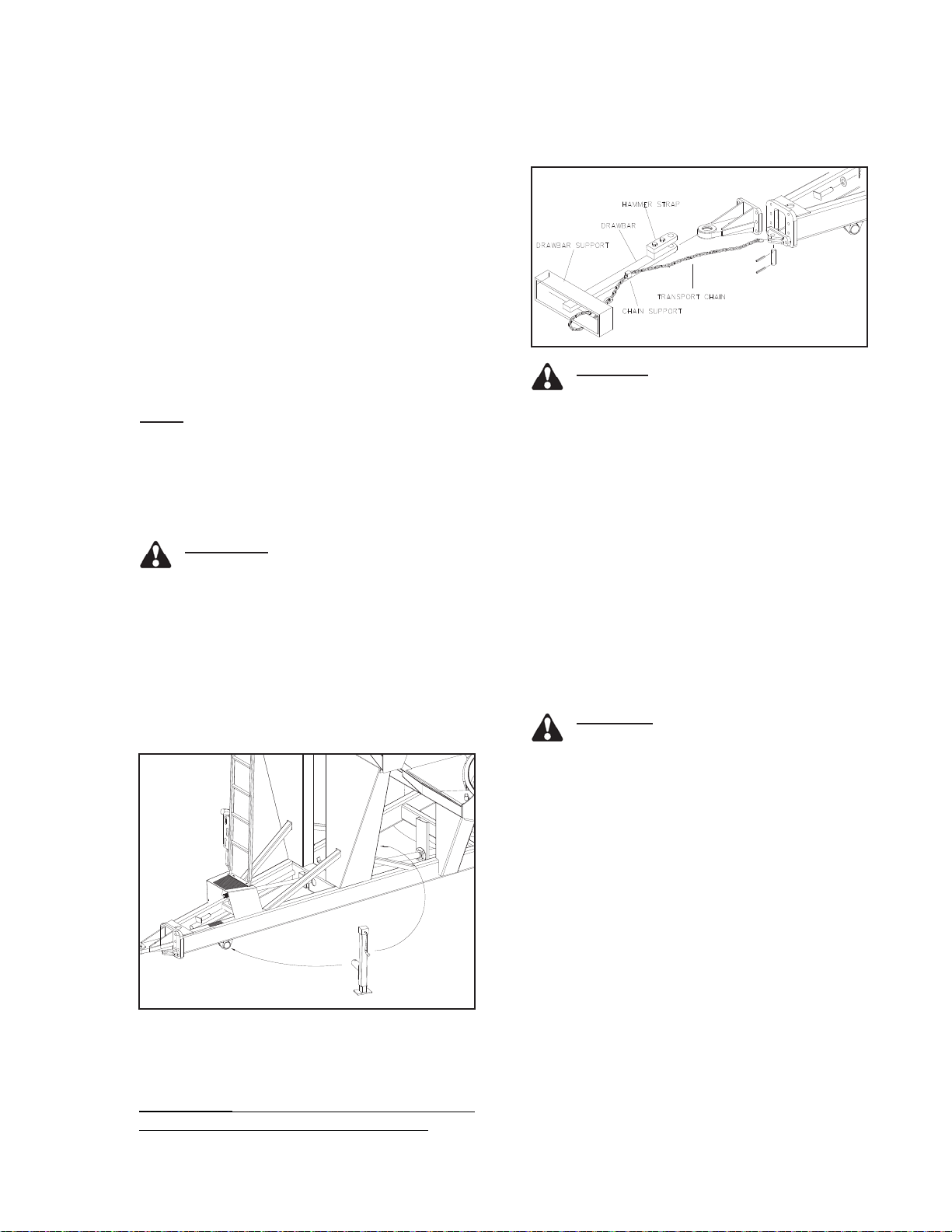
CAUTION! ALWAYS USE TRANSPORT
CHAIN WHEN TRANSPORTING IMPLE-
MENTS. FAILURE TO USE A TRANSPORT
CHAIN COULD CAUSE PERSONAL INJURY
IF CART BECOMES DISENGAGED.
Always use intermediate chain support when
connecting grain cart directly to a tractor. DO
NOT use the intermediate chain support as
the chain attaching point. Fig. 6 shows how
the transport chain must be installed between
tractor and grain cart.
Transport chain should have a minimum rat-
ing equal to the gross weight of implement
and all attachments. Use only ASAE approved
chains. Allow no more slack in chain than
necessary to permit turning.
CAUTION! REPLACE TRANSPORT
CHAIN IF ANY LINK OR END FITTING
IS BROKEN, STRETCHED, OR DAMAGED.
DO NOT WELD TRANSPORT CHAIN.
HITCHING TO TRACTOR
DRAWBAR CONNECTION
This cart is intended to be hitched to a trac-
tor drawbar. Do not attempt to hitch to any
other location on the tractor other than the
drawbar.
The cart is equipped standard with a single
tang hitch. A hitch pin between 1-1/2" or 2"
diameter must only be used with a clevis-
type tractor drawbar. An optional hammer
strap is available if your tractor has a single
tang drawbar.
NOTE: The use of a smaller diameter hitch pin
will result in additional clearance between the
hitch and pin. This additional clearance may
cause accelerated pin wear, tractor and cart
hitch wear, along with more pronounced jolting
from the cart during transport operation.
WARNING! DO NOT STAND BE-
TWEEN THE CART AND TRACTOR
WHEN HITCHING. ALWAYS ENGAGE PARK-
ING BRAKE AND STOP ENGINE BEFORE
INSERTING HITCH PIN.
After inserting drawbar pin, secure drawbar
pin with a locking device to help prevent
uncoupling during use.
Use jack to support an empty grain cart,
never a loaded grain cart.....always have a
loaded grain cart hooked to tractor.
IMPORTANT: Mount jack in storage location
indicated after cart is hitched to tractor.
JACK USAGE
TRANSPORT CHAIN
CONNECTION
253913
252919
REVISED 020107-11
Fig. 1
Fig. 2

2-4
Operation
HYDRAULIC CONNECTIONS
IMPORTANT: When coupling hydraulic hoses
to ports on tractor, be sure that coupler ends
are clean of dust, dirt and debris. Failure to do
so could contaminate hydraulic system result-
ing in excessive wear and possible failure.
Clean hydraulic hose couplers before connect-
ing to tractor. For convenience it is recom-
mended to connect the flow door circuit hoses
to tractor implement coupler #1, auger spout
circuit hoses to coupler #2, and attach auger
fold circuit to coupler #3.
This unit is equipped with color bands at-
tached to the hydraulic hoses. This will help
in identifying the hose function and correct
hook up.
Green Raise Auger
Lower Auger
Red Flow Door Open
Flow Door Close
Yellow Spout In
Spout Out
After initial set-up or replacement of any hy-
draulic component on the cart, air must be
removed from the cart hydraulic system. See
Purge Procedure.
Route hoses away from areas that may
cause abrasion or kinking of hoses during
operation.
Before disconnecting hoses from the tractor,
relieve pressure from the lines. See tractor
operator's manual for proper procedures.
Shut-off engine and apply parking brake be-
fore disconnecting hoses. Install couplers into
storage slots provided.
Fig. 3

2-5
Operation
LAMP BRACKET ADJUSTMENT
The lamp bracket width is adjustable. Ensure
that the brackets are adjusted such that the
reflectors are no more than 16" from outer
edge of the tires.
ELECTRICAL CONNECTIONS
WARNING! DO NOT ATTEMPT TO
INSTALL, ATTACH OR REPAIR ANY
ELECTRICAL APPLICATIONS ON THE CART
IF WORK AREA IS WET. ALLOW AREA TO
DRY BEFORE ANY WORK IS DONE. ELEC-
TRICAL SHOCK OR ELECTROCUTION MAY
RESULT IF WORK AREA IS NOT DRY.
This cart is equipped with a seven-pin SAE
connector plug which will connect with the
receptacle found on most newer tractors. If
your tractor does not have this type of re-
ceptacle, an SAE J-560 seven-point socket
can be purchased from your Unverferth dealer
(Part number 92824).
The wiring schematic for this cart, shown in
the maintenance section, complies with ANSI/
ASAE Standard S279.11/SAEJ137. Although
most newer tractors conform to this standard,
many older tractors can have a slightly differ-
ent electrical function than standard. Because
of this, always verify correct electrical function
before using this cart.
OPTIONAL LIGHT MODULE
In some areas, the lights may be required to
flash in the specific pattern described in ASAE
S279.10. In these areas, use the Enhanced
Turn Signal Kit (251095). See your dealer for
more information.
254920
220978
220912
REVISED 013107-11
Fig. 4 Fig. 6
Fig. 5
2-6
Operation
TOWING
This cart is not equipped with brakes. Ensure
that the towing vehicle has adequate weight
and braking capacity to tow this implement.
As a guideline, the towing vehicle should
be sized such that the cart does not weigh
over 1.5 times the towing vehicle weight.
Never tow a loaded grain cart over public
roads.
Do not exceed 10 mph during off-highway
travel. Do not exceed 8 mph when cart is
fully loaded.
Secure drawbar pin with a locking device
and lock tractor drawbar in centered position.
Connect the PTO driveshaft to the tractor.
Secure transport chain to tractor chain sup-
port before towing.
CAUTION! THE STANDARD TRANS-
PORT CHAIN PROVIDED IS FOR THE
BASIC CART WHEN TOWED EMPTY FOR
ROAD TRAVEL.
It is probable that this cart is taller, wider
and longer than the towing tractor. Become
aware of and avoid all obstacles and hazards
in the travel path of the equipment, such as
power lines, ditches, etc.
Always have auger folded back into storage
position when auger is not in use.
To prevent damage during turning when using
non-PTO equipped towing vehicles, store the
PTO driveshaft in the brackets provided on
the inside right frame rail.
AUGER OPERATION
WARNING! NEVER ENTER CART
WITH AUGER OR TRACTOR RUN-
NING. SERIOUS OR DEATH CAN OCCUR
DUE TO ENTANGLEMENT WITH ROTATING
COMPONENTS. ALWAYS STOP ENGINE
AND REMOVE KEY BEFORE ENTERING
CART.
DANGER! THE GRAIN CART IS NOT
INSULATED. KEEP AWAY FROM
ALL ELECTRICAL LINES AND DEVICES.
ELECTROCUTION CAN OCCUR WITHOUT
DIRECT CONTACT.
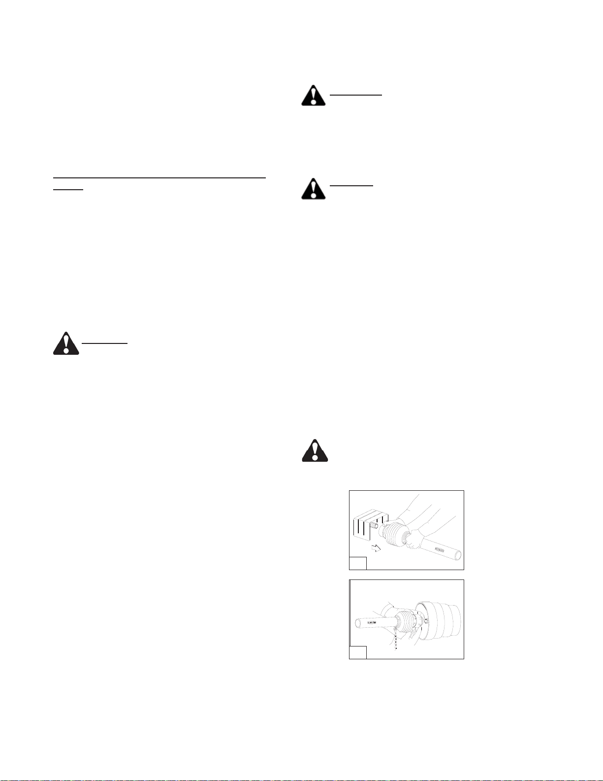
COUPLING THE PTO DRIVE SHAFT
(FIGS. E1 - E2)
Clean and grease the PTO and implement input
connection (IIC)
AS-Lock
1. Pull locking collar and simultaneously push
PTO drive shaft onto PTO shaft until the
locking device engages.
Push-Pull Lock
2. Pull locking collar and simultaneously push
PTO drive shaft onto PTO shaft until the
locking device engages.
Check to insure all the locks are securely
engaged before starting work with the
PTO driveshaft.
E1
E2 250968E
This manual suits for next models
1
Table of contents


