Product Code: 6045
Made in China to TQB Brands Pty Ltd specifications Page 3
Visit us at www.tqbbrands.com.au
SAFETY INSTRUCTIONS
SAFETY OPERATNG INSTRUCTIONS
Do not exceed the products rated maximum load capacity.
Always distribute objects evenly on the Workshop Trolley. Uneven weight distribution
could cause tipping.
Do not lean or climb onto the Workshop Trolley.
Only use this device for the purpose for which it has been designed.
Do not modify any component of this equipment.
When servicing, use only Tradequip identical replacement parts. Use of any other parts
will void the warranty.
Only use on a flat surface capable of supporting the Workshop Trolley and its rated
maximum capacity load. It is easy to lose control of the Workshop Trolley if attempting to
pull a load on a sloping or uneven surface.
Use the right product for the job. There are certain applications for which the Workshop
Trolley was designed. Do not modify the Workshop Trolley and do not use the Workshop
Trolley for a purpose for which it was not intended.
ASSEMBLY, OPERATION, PREVENTITIVE MAINTENANCE
1. FEATURES
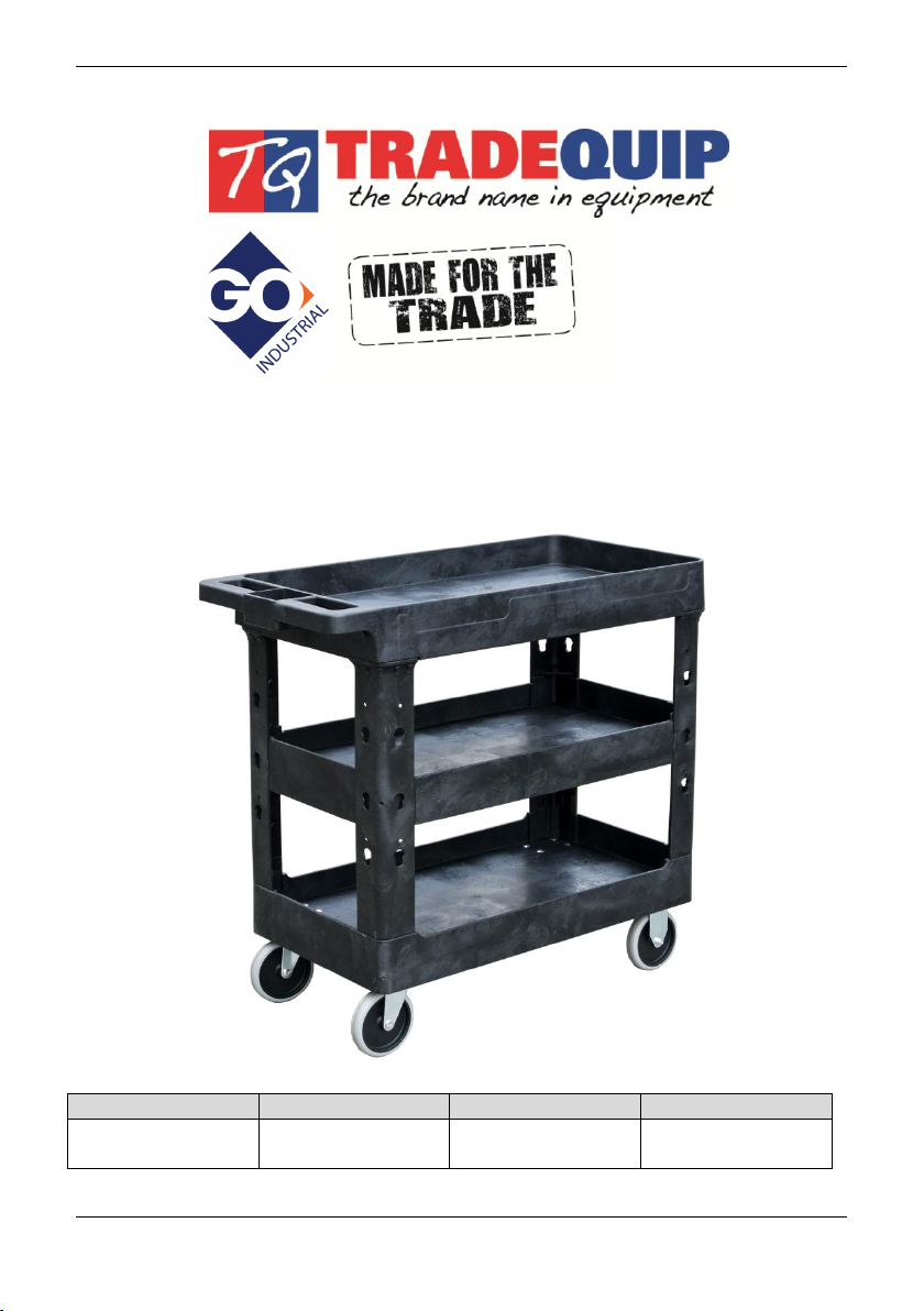
The Tradequip Polyethylene Workshop Trolley is widely used for collecting or storing
parts or tools when servicing machinery and vehicles etc.
2. ASSEMBLY
Unpacking: after removing the packing material, make sure the product is in perfect
condition and that there are no visible damaged parts. The packaging materials
(Polyethylene bags, polystyrene etc.), must be disposed of in an appropriate refuse
collection container. These materials must not be left within the reach of children as they
are potential sources of danger.
Assembly:
1. Place one Tray (1A) upside down on the work surface. Locate the Handle (3). Turn it
upside down with the hand holes on the outside away from the Tray (1A). Using a
rubber mallet, tap the Handle (5) down into the grooves on the Tray (1A) - see Figure
A.
2. Locate the two Beams (4). Place one on the Tray (1A) corner nearest the Handle (3),
and place one on the diagonal corner located on the outside of the Tray (1A) as in
the Assembly diagram. Make certain that the end with the screw holes is facing
upward. Using a rubber mallet, tap the Beams (4) down into the Tray (1A). Note:
Position the Beams so that the flange in each matches the space in the Tray (1A).
Refer Figure B.