Brewer's Ledge Treadwall CP User manual

Service Manual
Treadwall Model CP
tm
Copyright 1997 - Brewer's Ledge Inc.
J:\MANUAL~1\MODELC~1\SERVICESERVMANL.SAM 12/07/94 06/24/99

1. WHO IS COVERED?
This warranty may only be enforced by the original purchaser of the Treadwall ("Original Purchaser").
2. ORIGINAL PURCHASER OBLIGATIONS.
a. The Original Purchaser assumes full responsibility that this Treadwall®purchased meets the
specifications, capacity and other requirements of the Customer.
b. The Original Purchaser assumes full responsibility for the condition and effectiveness of the
operating environment in which the Treadwall is to function including spatial considerations.
3. HOW LONG IS THE WARRANTY?
According the following schedule, Brewer's Ledge Inc. warrants to the Original Purchaser of its
Treadwall fitness climber that under normal maintenance the Treadwall will be free from any defect in
materials or workmanship.
1.Structural Steel Frames and Welds:
(10) Ten years, parts, labor and freight.
2.All other components excepting cords and vinyl products:
(1) One year parts, labor, and freight.
3.Cords, sidecovers, safety pads:
(90) Ninety days parts, labor, and freight.
4. WHEN DOES THE WARRANTY BEGIN?
Warranty begins from date of delivery to Original Purchaser or date of installation in the case of
factory assembly. In the case of either Demonstration or Trial Agreement and related purchase, from the
date of the original delivery.
5. WHAT IS NOT COVERED.
a.Normal wear and tear is excluded from this warranty. No warranty shall be provided in the event
the Treadwall is modified by original purchaser, for parts not approved by Brewer's Ledge Inc., or for
warranty-related service other than by personnel authorized Brewer's Ledge Inc.
b.Damage incurred by negligence during movement, assembly, or break-down of the
Treadwall by the Original Purchaser or personnel contracted by the Original Purchaser is
excluded from this warranty. The sale of special tools and instructional materials to the Original
Purchaser and any training of the Original Purchaser's staff by Brewer's Ledge Inc. related to the
movement, assembly and break-down of the Treadwall does not imply any warranty against Original
Purchaser negligence and does not void this exclusion. Brewer's Ledge Inc. reserves the sole right to
determine the origin of damage as related to this provision.
6. LIMITATION OF DAMAGES AND IMPLIED WARRANTIES.
Treadwall limited warranty
®

a.Except as provided herein, Brewer's Ledge Inc. makes no express warranties; implied
warranty of merchantability or fitness for a particular purpose is limited in its duration to the duration of
the written limited warranties set forth herein.
b.In no case shall Brewer's Ledge be liable for any special, incidental, or consequential
damages based on breach of warranty, breach of contract, negligence or any other legal
theory. Such damages include but are not limited to, loss of profits, loss of use of the equipment or any
associated equipment, the cost of capital, the cost of substitute equipment, facilities or services,
downtime, the claims of third parties, including customers, and injury to property.
This limitation does not apply to claims for personal injury where such limitation would be a violation of
the applicable law. Some states do not allow the exclusion or limitation of incidental or consequential
damages, so the above limitation or exclusion may not apply to you.
7. TERMS OF WARRANTY
The terms and conditions of this warranty are applicable as between Brewer's Ledge and Original
Purchaser to the sale of Treadwall equipment to Original Purchaser.
8. STATE LAW RIGHTS
This warranty gives you specific legal rights, and you may also have other rights which vary from state
to state.
Copyright 1995, Brewer's Ledge Inc.

Machine Diagram
Cable turnbuckle
Interior turnbuckle
Chain tension adjuster
Access hole
Adjustable bearing
CONTROL
PANEL
Pulley bar
Access hole
Control line
Speed control
Angle adjust
wheel
Cable guard
Locking
disk
Treadwall model CP - side view
Drive chain
access hole

Treadwall®maintenance is easy and requires only lubrication and attention to a number of
adjustments relating to the alignment of the wall. The most important maintenance of the Treadwall
occurs during the first month of operation when the chains and cables are stretching to their final length. It
is very important to keep the angle-adjuster cables tight during this break-in period so that the winds
remain even and do not overlap. Also the drive chain and panel chains must be tightened after 2-3
weeks of use. Instructions for these adjustments are found inside of the control panel cover.
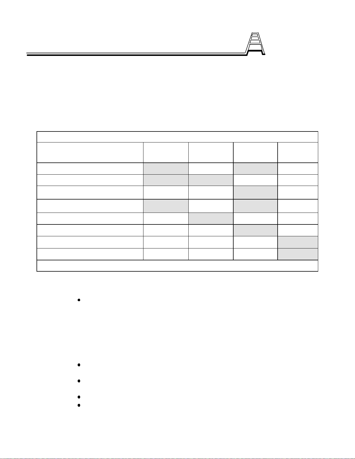
TREADWALL® MAINTENANCE SCHEDULE
Maintenance Item First month Two Months Six Months Yearly
**Drive chain X X
**Adjuster Cables X X
**Check Wall Alignment X
**Adjust Main Chain Tension X X
Clean Holds X
**Check Harness cord for wear X
**LubricateChains X
Grease Bearings X
** MAINTENANCE PRIORITY ITEMS
1. First month
A. Adjust the drive chain and main chains
See the inside of the control panel door for easy instructions.
People required: 1
Time required: 10 min.
Tools required: Adjustable wrench
B. Re-tighten Adjuster Cables on each side at least every week or when loose for the first
month. This is very important for the proper functioning of the angle adjustment as the cables tend
to stretch during the break-in period.
If they become loose, the cables can become tangled and break. They should be
kept firm, with no slack.
Use the turnbuckles at the back end; loosen their lock nuts, and tighten in a correct
manner, then re-tighten lock nuts.
A small screwdriver is useful for tightening the turnbuckles.
Swing wall back and forth to check after tightening. Cable turns should stay
together. Tapping cable helps to equalize both sides.
Maintenance and Service

People required: 1
Time required: 10 minutes
Tools required: Small screwdriver, small adj. wrench
2. Two Months.
A. Check Main Chain and drlive chain tension after the second month of use. Although the
chains used on the Treadwall are designed for much harder use than the Treadwall will give them,
they will stretch slightly upon breaking in. This causes the wall to become stuck. Reversing the
wall slightly frees it up, but it will soon stick again. This is caused by the panels jamming as they try
to re-enter the channels near the bottom at the back. Consequently, we recommend taking the
time after the second month to check the tension.
See the Service Bulletin # 20.
People required: 1
Time required: 10 minutes
Tools required: 9/16" wrench
B. Cleaning the holds is usually scheduled every two months. However individual usage varies,
and the amount of dirt build-up on holds has no long-term effect on the holds themselves.
Use a dishwasher to clean the dirt from holds.
If a dishwasher is not sufficient, use a scrub brush to loosen the dirt.
C. Examine the Harness Cord occasionally to check wear on the cord.
Check area of cord under the cord locks attached to the harness. If the outer
sheath is frayed, replace as soon as convenient.
The Harness Cord runs from the Harness to the Upper Pulley bar; Replacement of
the cord does not involve re-threading the cord inside the Upper Pulley Bar.
See Service Bulletin # 7.
3. Six Months.
A. Check adjustment of Main Channels relative to the ends of the moving
climbing panels.
Look down watch the panel ends as they round the bottom: does either end touch
the channel?
By adjusting the relative tension on x-braces that run diagonally between the two
channels inside the wall, you can shift the channels relative the moving wall.
Access the turnbuckles through the excess holes on the lower part of each channel.
The turnbuckles should be wired closed. Remove the wire, tighten turnbuckle on the
opposite side of the rubbing panels, and recheck for clearance at the panel ends.
Ideally both ends should pass with equal clearance. You may have to adjust both
turnbuckles slightly to achieve this. Re-wire turnbuckles closed.
People required: 1
Time required: 15 minutes
Tools required: Small screwdriver, small open end wrench, pliers
B. The Main Chain and Drive Chain should be lubricated every sixmonths.
Access chains through the access holes on the lower part of Main Channels and
the hole above the control panel.

With an assistant moving the wall slowly, direct nozzle of a spray lubricant towards
chain, and lightly coat the chain. Do both sides.
Preferably, do at the end of the day and let sit overnight with old newspapers below
to catch any drips.
We recommend a lubricant such as "Triflow" which is easily obtained at a bike
shop and does not have an adverse odor or appearance.
People required: 2 people
Time required: 20 minutes
Tools required: "Triflow" or equivalent spray lube with small tube to direct
flow.
4. Yearly Maintenance.
A. The bearings at the top and bottom shafts should be greased every year. The bearing
come pe-greased, and depending on the level of usage,. a small amount of grease should be
applied to the four bearing yearly.
Do NOT over-grease: only a small amount will be necessary.
People required: 1 person
Time required: 15 minutes
Tools required: Grease gun with bearing grease.
For service questions, please call Brewer's Ledge Inc. in Boston, Mass.
800-707-961

TROUBLESHOOTING GUIDE -- TREADWALL® FITNESS CLIMBER
Problem Cause Solution
Wall is sluggish: lighter
weights will not pull wall
down.
Channels misaligned.
Chains too tight.
Internal x-bracing too
tight.
Broken angle adjuster
cable.
See Service Bulletin #20.
See Service Bulletin #4.
Wall sticks occasionally.
(Backing-up momentarily
frees wall).
Chains too loose See Service Bulletin #20.
Motor makes excessive
noise Low hydraulic oil. Add oil to Pump Assembly. Open panel, remove pipe
cap, and inspect: oil should be within 1" of top. Use 30
wt. non-detergent oil. Rotate motor as filled to remove
air pockets. Cover fill opening with rag as rotating to
prevent spills. Total capacity of system: 1 pint.
Wall makes excessive
noise Chain too loose.
Panel end screw backed
out.
See Service Bulletin #20.
Locate side that is rubbing (noisy) by means of sound
and scraped paint on inside of channels (usually at the
top). With assistant turning wall, observe ends of
panels at top: look for screw that has backed out.
Re-tighten. If stripped, remove and replace using glue
on threads.
Adjuster cables are
breaking or fraying. Cables windings too
loose. See Service Bulletin #4.
Wall keeps rolling "under"
the climber's foot. Harness line adjusted
improperly Make sure harness line is pulled tight through the
line-locks before climbing.
Wall sways side-to-side. Internal x-bracing too
loose. Tighten Internal x-bracing. Do not over-tighten. Tighten
until just firm and adjust for panel end clearance (See
Service Bulletin # 22).
Hold rotates. Hold bolts not sufficiently
tightened. Re-check hold bolts; re-tighten if necessary.
Wall too far to one side (not
centered in frames).Main (external) X-bracing
needs re-adjustment. See Service Bulletin # 2.
Hydraulic Assembly leaks
oil. Valve gland-nut loose. See Service Bulletin # 6.
Troubleshooting Guide

Cord has too much friction.
Cord is frayed/broken inside
Top Pulley bar.
Cord is off pulley. Check pulley where line exits the pulley bar at top right
side of machine.
Cord is frayed at Harness. Cord is worn out. Replace harness cord.
Counter does not operate
Battery dead
Microswitch is broken or
misadjusted Remove one panel to access switch. Click switch
manually to check operation. To check switch function,
short out terminals with a paperclip: this should cause
counter to "count".
- if counter counts, replace microswitch.
- if counter does not function, check counter battery
and counter itself.
Replace the battery in the counter. The Climbometer
data panel has an access door on the back that
screws on.
The smaller foot-counter which is supplied on some
Treadwalls must be removed from its case to access
the battery compartment.
The following Service Bulletins are included in this manual:
Service Bulletins # 1, 2, 3, 4, 6, 7, 8, 10, 11, 18, 20, 21, 23, 27, 28
@These Bulletins are those that pertain to standard service issues. As needed, we develop further Service
Bulletins for specific tasks. May, 1996
Now Available from Brewer's Ledge:
The Treadwall®Spare Parts Kit (for Treadwall model CP)
CONTENTS: (1) angle adjuster cable with instructions
(2) harness lines with instructions
(1) harness line lock
(2) control lines with instructions
(1) touch-up paint for panels
(1) bag - spare tee-nuts and panel bolts
A handy assortment of maintenance parts that will help you keep your Treadwall in top running
condition with a minimum of downtime.
Price: $50 (individual prices = $63.50) Visa accepted
Call: 1-800-707-9616

INDEX OF SERVICE BULLETINS
Treadwalltm Climbing Simulators -- CP
Number
0Index
1Panel Removal
2Frame Adj. w/ X-brace
3Adjustment of the internal Microswitch
4Replacement of Cables - Angle Adjuster
6Gland Nut Adjustment - Hydraulic Valves
7Harness Cord Upgrade and Adjustment
8Replacement of Brake Control line - Upper Pulley Bar
10 Adjustment of Chain Tension
11 Instructions for Electronic Counter
18 Hold placement
20 Adjustments for a stiff Treadwall - NTW
21 Sidecover Elastics - assembly and use
23 Replacement of tee nut on Treadwall panels
27 Securing internal x-bracing
28 Moving the Treadwall
38 Correcting panels rubbing on channels

Treadwall®Service Bulletin #1: Panel removal
The Treadwall wall panels are bolted to a set of chains. These two chains form a continuous loop around the top and
bottom axles. Each panel is attached by two bolts at the ends to flanges mounted on the chains.
Tools needed: 1/8" Allen wrench, 3/8" box end or open end wrench, needle nosed pliers.
Panel hardware: 10-32 x 1 1/2" socket-head, flat-head bolts. 10-32 nylon locknuts.
Removing a panel is simple and requires about 15 minutes effort. Depending on the type of side channels your unit has,
there are two methods for removing a panel. NOTE: Before choosing a panel to remove, examine the bolts - during
installation the holes for the Allen keys may have become slightly distorted. Choose a panel with non-distorted holes
(i.e.. the Allen wrench slips in the 4 bolts easily...).
Method # 1 ( side channels with a 2" round access hole)
Rotate wall so desired panel is at the bottom. This will give access the locknuts inside the panels. You may wish to lie
on your side to reach the locknuts.
With the Allen wrench and open end wrench, remove the four bolts and their locknuts. The panel will drop down.
Rotate the wall to give the desired height, and perform what ever service is necessary.
Removal of more than one panel may be accomplished at standing position by reaching in through the first open panel
and accessing the locknuts of the panel below.
Replacement of the panel must also be done at the bottom. Use the needle nosed pliers to hold the locknuts in position.
Note that if you have removed more than one panel, these may be replaced by slipping them in at the bottom, rotating
the wall upwards, and re-inserting the bolts in standing position.
MAKE SURE TO ORIENT PANELS SO THAT PANEL BARS AND HOLD-MOUNTING HOLES ALTERNATE!!
Method #2 (channels with a 2" x 5" rectangular hole)
Rotate wall so that desired panel is in front of the rectangular opening. Remove four panel bolts and their locknuts by
using the opening to access the back. Rotate the wall downward and allow the panel to drop out at bottom.
Multiple panels can be removed in a similar manner. Rotate the wall to give the desired height, and perform what
ever service is necessary. Replace panels by inserting panel at bottom and rotating upward until it is in front of
rectangular opening. Replace all four bolts.
MAKE SURE TO ORIENT PANELS SO THAT PANEL BARS AND HOLD-MOUNTING HOLES ALTERNATE!!
Access
holes
Panel bolts: four total
Side
P
If you have any questions, please do not hesitate to call
8:30-5 E.S.T.
1-800-707-9616.
Copyright 1994, Brewer's Ledge Inc.

Treadwall®Service Bulletin #2: FRAME ADJUSTMENT WITH
"X-BRACING"
The Treadwall is aligned with the support frame by adjusting the diagonal bracing at the back of the
machine. It is important to properly align the wall, both for angle adjustment and performance.
With the wall at vertical, note the gaps between the side channels and the two main side frames.
When the wall is centered, the gap on the right side (just below the angle-adjuster wheel) should be 3 1/2"
If the wall needs adjustment, loosen both turnbuckles at the bottom of the "X-Braces" in the back;
re-tighten on the side to which you wish swing the wall. For example, if the wall is too close to the right
side, you will need to tighten the left "X-bracing" to bring the wall closer to the left side.
You may find as you tighten one side, you will have to continue to loosen the opposite turnbuckle to
give yourself enough slack.
When you have finished adjusting, take up the slack in the other turnbuckle, check the adjustment, and
tighten the locknuts to prevent the turnbuckles from loosening.
If you have any questions,
please do not hesitate to call 8:30-5
E.S.T.
1-800-707-9616.
"X-bracing"
and
Turnbuckles
"X-bracing"
and
Turnbuckles
note that channels
should be parallel
to the frames
VIEW FROM BACK
OF TREADWALL
3 1/2"
Note that each turnbuckle has a locknut
that must be loosened before adjusting.

Treadwall®Service Bulletin #3: Adjustment of microswitch
The Treadwall counter is activated by a simple microswitch which counts every other 6" panel, each click/count
indicating 1' of distance. The microswitch is mounted inside the panels with its arm passing over every other panel
stiffener bar. This arm movement (clicking sound) breaks a tiny electrical current from the counter which causes a
"count".
Access to the microswitch is by removal of a panel . The wall is then rotated to expose the microswitch. See Service
Bulletin No. 1 "Removal of a Panel".
If a counter is not working, check the following items:
a. Examine the microswitch; is the arm is bent and aligned correctly? See diagram below.
b. Is the counter itself working properly? This can be checked by removing one wire from the
microswitch and touching it to the other wire - the counter should register each touch.
c. If the microswitch was just installed, check to ensure you have attached one wire to the
terminal marked "common", with the other to either remaining terminal.
If you are installing a new microswitch, be sure to mount the switch on the correct side of the bracket so that the arm
clicks over every other panel bar. Depending on the bracket supplied with your machine, the microswitch will have
to be mounted on the inner or outer side of the bracket. It may only go in one position to catch every other panel.
Test microswitch at all angles; there is some variation in panel position depending on angle.
I
If you have any questions,
please do not hesitate to call 8:30-5
E.S.T.
1-800-707-9616.
Panel
Test bent arm - a
clicking sound should
be heard each time it
passes over a panel
Microswi
Panel
Make sure raised tip does
not catch opposite panel bars
as they descend!
Make sure switch counts
every other bar...place switch
on correct side of bracket.

TREADWALL ANGLE-ADJUSTER CABLE
Type 1
This cable fits Treadwalls previous to serial #96 03 01 (except for the earlier
"Classic Treadwall")
On these machines, the cable is held onto the front upright by a shackle that
attaches to a loop on the frame (see diagram).
The original cable was provided with a hook-and-eye turnbuckle, permanently
swaged onto the cable. If this type of turnbuckle is on the machine, you will need to
order a new hook-and-hook style turnbuckle. If the cable has been previously
replaced with a hook-and-hook style turnbuckle, you can use the old turnbuckle with
the new cable.
Front frame
Loop
Cable
Shackle Washer
(on replacement cable only)
Hook-and-hook turnbuckle
Hook-and-eye turnbuckle
Brewer's Ledge
34 Brookley Rd.
Jamaica Plain, MA 02130
(800) 707 9616

Treadwall®Service Bulletin #4: REPLACING CABLES (type 1)
1. Tools needed:
Ball peen hammer
A small box wrench with closed end. (Exact size not important.)
2. Procedure (Same on both sides):
Removing...
1. Lock wall in a position so hole in Adjuster Pipe faces up (Note how cable dips into hole near
the center of the windings and is locked in place with a bolt inside pipe.)
2. Lift side cover.
3. Remove chrome Adjuster wheel (right side) or plastic cap (left side) from the end of Adjuster
Pipe. The wheel simply unscrews from the pipe. To remove it, engage the locking disk to the
channel and turn the wheel hard to the left. Remove the ball from the locking rod and slip the
wheel off.
4. Loosen and disassemble turnbuckle. Slip the end of the cable through the guide loop.
5. Remove Cable Guard.
6. Using the closed end of a wrench, reach into Adjuster Pipe end and pull out bolt that holds
cable to pipe.
7. Remove shackle from front loop, and cable will come free.
Installing...
1. New cable is pre-bent at a certain spot. Push this bend into Adjuster Pipe hole so that end with
shackle leads toback of machine. (After winding, the cable will leave pipe at bottom as in
fig. 1. and shackle will go towards front of machine)
2. Re-insert bolt to catch the loop of cable inside pipe.
3. Pull up on cable to take-upall cable slack around the bolt that is inside pipe.
4. Hammer down cable on both sides where it exits the hole. No need to pound cable
excessively; this is just to put a bend in cable so it
will exit hole and lay nicely around pipe.
5. Wrap the shackle end around pipe so as to follow a
left hand thread as shown in fig. 1. Important: On
earlier Treadwalls, the cables were wound as a right
hand thread. Even if only one cable is being
replaced, both cables must be wound the same
way. Check the other cable and rewind it if it is not
like fig. 1. Also,both cable guards will have to be
replaced in this case to accommodate the new
winding.
6. The number of wraps will be clear from the length of
the cable: the shackle and turnbuckle will only reach
when the correct number of turns is on the pipe.
7. Put on shackle.
8. Wrap turnbuckle end and lead up through corner loop
at back of unit. fig. 1
carefully
note direction
of wind.

9. Hook turnbuckle and tighten. Make sure wraps of cable on pipe are evenly wound and tight
together as you tighten turnbuckle.
10. Re-install chrome Adjuster wheel and by swinging wall front and back, stretch new
cable. Re-tighten turnbuckle.
11. Repeatabove step at least a dozen times to stretch cable, tightening turnbuckle to take up
slack.
12. Keep turnbuckle tight - do not be afraid to tighten turnbuckle with new cable.
13. When cable is stretched, it is time to install the cable guard. Slip the cable guard over the
windings so that one hook is engaged with the back end of the cable. Loosen the turnbuckle
a few turns. Now hold the windings at the bottom of the pipe to keep them from loosening,
and with your other hand remove the shackle from the front loop. Continue to hold the
windings in place while you work the front end of the cable under the other hook. Re-attach
the shackle and tighten the turnbuckle. This process is easier than it sounds as long as you
don't let go of the windings. You might want to have someone help with the shackle.
14. Make sure cable wrappings inside the guard are still tight together when you are finished -
this may involve using the hammer and wrench to tap the windings back together after you
have begun to re-tighten turnbuckle.
15. Swing wall front and back to make sure all is working and look for windings that are spread
apart.
16. Once more, tighten turnbuckles to remove any slack.
17. Tighten locking nut on turnbuckle.
18. Note: Cables can be sprayed with silicone spray to significantly increase their life
expectancy
*****PLEASE re-tighten cables each day for the first 4 days to ensure proper working.*****
If you have any questions,
please do not hesitate to call 8:30-5
E.S.T.
1-800-707-9616.
(Bulletin # 4 - page 2)

TREADWALL ANGLE-ADJUSTER CABLE
Type 2
This cable fits Treadwalls serial #96 03 01 and higher.
On these machines, the cable is held onto the front upright by a pin through a
rectangular sleeve welded onto the front of the frame (see diagram).
The cable is provided without a turnbuckle. If the original turnbuckle is damaged,
order a new hook-and-hook style turnbuckle from Brewer's Ledge. Otherwise, use the
old turnbuckle.
Front frame
Cable
Pin
Rectangular sleeve
Brewer's Ledge
34 Brookley Rd.
Jamaica Plain, MA 02130
(800) 707 9616

Treadwall®Service Bulletin #4a: REPLACING CABLES (type 2)
1. Tools needed:
Ball peen hammer
A small box wrench with closed end. (Exact size not important.)
2. Procedure (Same on both sides):
Removing...
1. Lock wall in a position so hole in Adjuster Pipe faces up (Note how cable dips into hole near
the center of the windings and is locked in place with a bolt inside pipe.)
2. Lift side cover.
3. Remove chrome Adjuster wheel (right side) or plastic cap (left side) from the end of Adjuster
Pipe. The wheel simply unscrews from the pipe. To remove it, engage the locking disk to the
channel and turn the wheel hard to the left. Remove the ball from the locking rod and slip the
wheel off.
4. Loosen and disassemble turnbuckle. Slip the end of the cable through the guide loop.
5. Remove Cable Guard.
6. Using the closed end of a wrench, reach into Adjuster Pipe end and pull out bolt that holds
cable to pipe.
7. Remove pin from front frame, and cable will come free.
Installing...
1. New cable is pre-bent at a certain spot. Note that the bend is not exactly in the middle, so that
one end is slightly shorter than the other. Push the bend into Adjuster Pipe hole so that the
shorter end leads toback of machine. (After winding, the cable will leave pipe at bottom as in
fig. 1 and the shorter end will go towards frontof machine)
2. Re-insert bolt to catch the loop of cable inside pipe.
3. Pull up on cable to take-upall cable slack around the
bolt that is inside pipe.
4. Hammer down cable on both sides where it exits the
hole. No need to pound cable excessively; this is just
to put a bend in cable so it will exit hole and lay nicely
around pipe.
fig. 1
carefully
note direction
of wind.

5. Wrap the shackle end around pipe so as to follow a left hand thread as shown in fig. 1.
6. After four turns, attach the cable to the front of the frame with the clevis pin and cotter pin.
7. Wrap the other end and lead up through corner loop at back of unit. The number of wraps will
be clear from the length of the cable: the turnbuckle will only reach when the correct number of
turns is on the pipe.
8. Hook turnbuckle and tighten. Make sure wraps of cable on pipe are evenly wound and tight
together as you tighten turnbuckle.
9. Re-install chrome Adjuster wheel and swing wall front and back tostretch the new cable.
Re-tighten turnbuckle.
10. Repeatabove step at least a dozen times to stretch cable, tightening turnbuckle to take up
slack.
11. Keep turnbuckle tight - do not be afraid to tighten turnbuckle with new cable.
12. When cable is stretched, it is time to install the cable guard. Slip the cable guard over the
windings so that one hook is engaged with the front end of the cable. Loosen the turnbuckle a
few turns. Now hold the windings at the bottom of the pipe to keep them from loosening, and
with your other hand remove the turnbuckle from its loop. Continue to hold the windings in
place while you work the rear end of the cable under the other hook on the cable guard.
Re-attach the turnbuckle and tighten it. This process is easier than it sounds as long as you
don't let go of the windings. You might want to have someone help with the turnbuckle.
13. Make sure cable wrappings inside the guard are still tight together when you are finished -
this may involve using the hammer and wrench to tap the windings back together after you
have begun to re-tighten turnbuckle.
14. Swing wall front and back to make sure all is working and look for windings that are spread
apart.
15. Once more, tighten turnbuckles to remove any slack.
16. Tighten locking nut on turnbuckle.
17. Note: Cables can be sprayed with silicone spray to significantly increase their life
expectancy
*****PLEASE re-tighten cables each day for the first 4 days to ensure proper working.*****
If you have any questions,
please do not hesitate to call 8:30-5
E.S.T.
1-800-707-9616.
(Bulletin # 4 - page 2)

This manual suits for next models
1
Other Brewer's Ledge Fitness Equipment manuals
Popular Fitness Equipment manuals by other brands

FRENCH FITNESS
FRENCH FITNESS FF-FSR70 Assembly manual

Nautilus
Nautilus INSPIRATION STRENGTH NP-L1130 Owner's manual and installation instructions

versa climber
versa climber 108 SM Operational manual

Epic
Epic ST 280 user manual

Kamagon
Kamagon Kamagon Ball 9" owner's manual

NAVYSEALS
NAVYSEALS FLOWBAR quick start guide