BrickElectric BEM107 User manual
www.BrickElectric.com
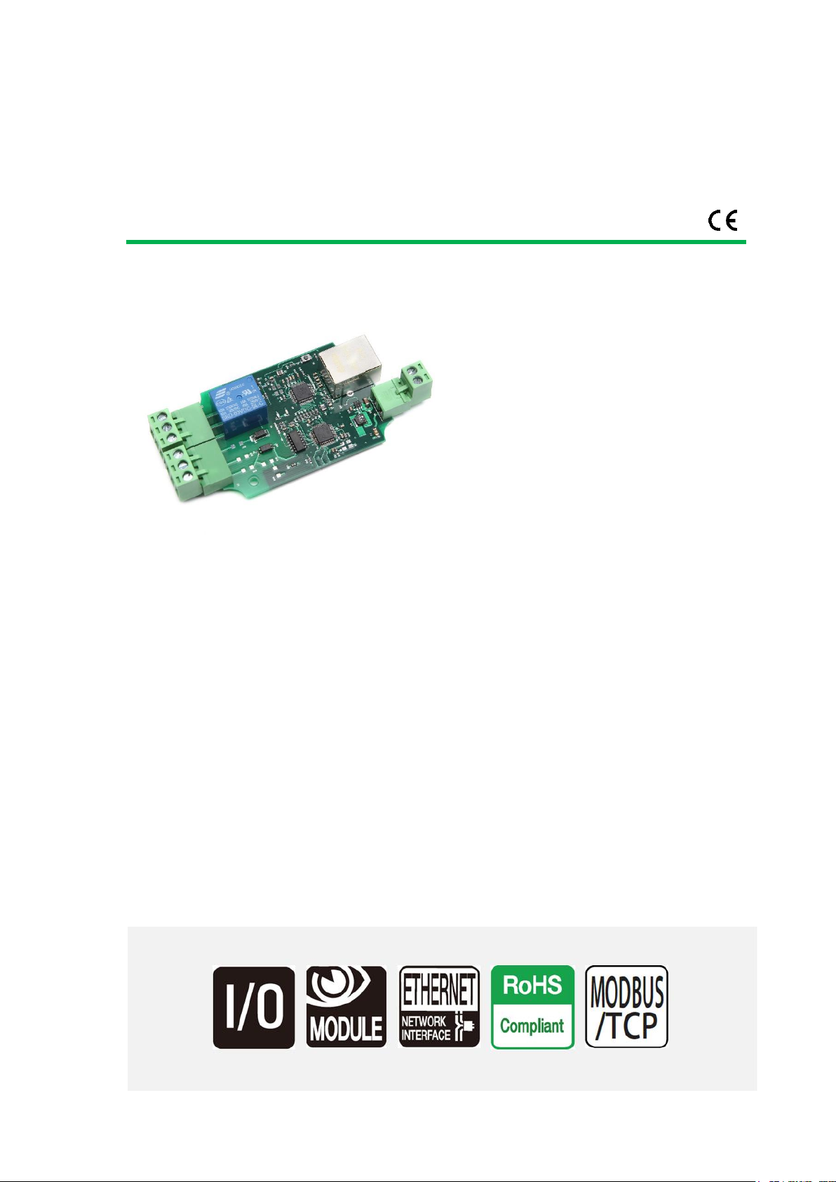
BrickElectric Ethernet Relay
BEM107
Excellent network building block
Features
⚫WEB control
⚫X-Connect
⚫Modbus-TCP
⚫Hardware Reset
⚫5 - 24 VDC power supply
⚫EasyBus - simple solution
⚫Android App
⚫LAN mode
⚫DHCP - Plug and play
⚫Internet Control
⚫Password Protection
Introduction
BEM107 is an Wide Supply Input, Ethernet Remote I/O Module, with 1 output channel and 1
input channel, and provide with both enclosed and open type housing. Its Ethernet connector
provides 10/100baseT interface.
It supports EasyBus-TCP, HTTP control, and Internet control protocols, suitable for being used
with servers, computers, mobiles, routers, etc., to provide remote control and monitor.
With DHCP functions, it doesn't need to make any settings anymore in field. So just plug and
play, power it on and then enjoy your remote control.
BEM107 is a new generation product with more functions and higher stability. Control mode
"toggle" and "automatic cycle operation" are provided additionally.

www.BrickElectric.com
Table of Contents
1. Device Overview............................................................................................................................3
1.1 General Ratings ...................................................................................................................3
1.2 Connection Diagram............................................................................................................3
2. Specifications ................................................................................................................................3
2.1 Recommended Operating Conditions.................................................................................3
2.2 Default Software Settings....................................................................................................4
3. Easy Start.......................................................................................................................................5
3.1 HTTP Mode..........................................................................................................................5
3.2 LAN Mode............................................................................................................................6
3.3 Internet Mode:....................................................................................................................8
4. General Functionality....................................................................................................................9
4.1 Basic Network Communications .........................................................................................9
4.2 Save Parameters..................................................................................................................9
4.3 Reboot.................................................................................................................................9
4.3 DHCP Function ..................................................................................................................10
4.4 Static IP Address................................................................................................................10
4.5 Relay outputs control ........................................................................................................11
4.6 Password protection..........................................................................................................16
4.7 Http port setting................................................................................................................17
4.8 Hardware reset button......................................................................................................17
4.9 Identification & customized information ..........................................................................18
4.10 Read Inputs .....................................................................................................................19
5. X-Connect....................................................................................................................................20
5.1 X-Connect Map Setting .....................................................................................................20
5.2 X-Connect Map Parameter List..........................................................................................21
6. Modbus-TCP................................................................................................................................23
7. Fast Program Reference ..............................................................................................................24
7.1 Easybus Specifications.......................................................................................................24
8. Support & Contact us..................................................................................................................38
www.BrickElectric.com
1. Device Overview
1.1 General Ratings
Power Consumption
3W max.
Operation Temperature
-30℃to +85℃
Module Size
75mmx50mmx20mm
Weight
-
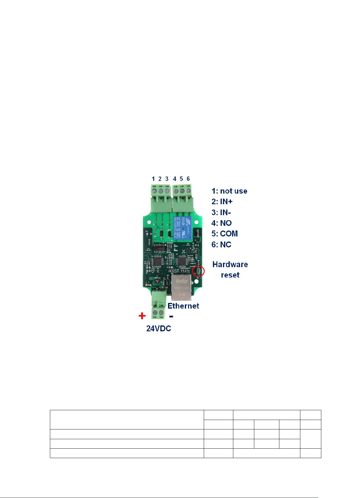
1.2 Connection Diagram
Fig. 1.1
2. Specifications
2.1 Recommended Operating Conditions
Parameters
At T = 25℃, Vsuplly = 5V unless otherwise specified.
Symbol
Values
Unit
Min.
Typ.
Max.
Operating voltage
Vs
5
-
24
V
Output Relay Rating
-
250VAC/10A
-

www.BrickElectric.com
125VAC/10A
24VDC/10A
12VDC/10A
2.2 Default Software Settings
Default Settings
⚫IP Setting:
IP address: 192.168.1.105
Subnet Mask: 255.255.255.0
Gateway: 192.168.1.1
DHCP: disable
⚫Latest Firmware Version
V107.0-00
You can download latest firmware for
free.
⚫HTTP function
State: Enable
Port: 80
⚫Internet Control
State: Enable
Platform with App: Android
/ iOS(in prepare) / Windows(in prepare)
Cross-Platform (Web Browser) in prepare
www.BrickElectric.com
3. Easy Start
A Practical step-by-step operation guide for starters
This part is a step-by-step tutorial explaining how to start with BEM107. We'll not discuss too
much details here. The only idea here is to make it work by minimum steps. For more
information, please refer to later chapters.
3.1 HTTP Mode
1. Connect BEM107 with your routers or computer via a standard Ethernet cable. And then
power it on with 5 - 24VDC power supply. (see fig.1.1 at page 2)
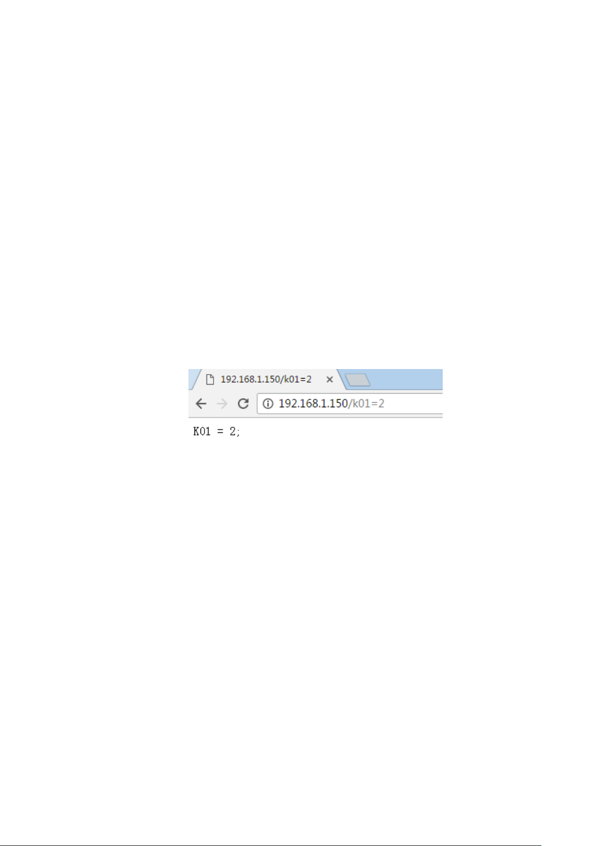
2. Open any Browser, for example Chrome is used here as demonstration. Please enter URL:
http://192.168.1.105/k01=2. Relay channel 1 will be toggled, and a message will be returned to
your browser. Congratulations!

www.BrickElectric.com
3.2 LAN Mode
1. Connect BEM107 with your routers or computer by Ethernet cable, and then power it on with
5 - 24VDC power supply. (see fig.1.1 at page 2)
2. Open any TCP test tool (if you don't have any, or you don't know what a TCP test tool is, you
can use BE-Manager, it is within our software package). Open it and see the following Fig.1.2:
Fig.1.2
3. Click "Connect" button, and wait for module connected. Then, it is able control the relay
module. Click "CH1 OFF" button, and the relay channel 1 will be switched on. See Fig.1.3

www.BrickElectric.com
Fig.1.3

www.BrickElectric.com
3.3 Internet Mode:
1. Connect BEM107 by Ethernet cable. And then power it on with 5-24VDC power supply. (see
fig.1.1 at page 2)
2. Open "Hello Brick" app for android at any android phone, register a user and then have fun
with Internet control.
3. If you need online help or need to contact us for customized functions, please click the bottom
right red "online help button". One of our daily on duty R&D engineer will talk to you directly.

www.BrickElectric.com
4. General Functionality
4.1 Basic Network Communications
The main method of communication to BEM107 is a standard Ethernet communication.
This communication protocol makes use of Network Sockets or HTTP protocol to create
point to point tunnels that data can flow through bi-directionally. In this way, the computer
that is controlling the relay can send commands and shortly thereafter receive the
response through the same Socket/Web Page.
Communications
In most programming languages, all you need to do to open a socket is to import the
appropriate plug-in, build the socket object, and connect the socket using the IP Address
and Port Number of the target device.
MAC Address
You can find the MAC Address of the module at the simple start manual delivered together
with module package.
4.2 Save Parameters
After power cycle, BEM107 will lose its parameter modifications if you don't actively
require it to save modified parameters into internal nonvolatile memory. For examples, IP
Address, Gateway address and Net mask.
Assuming module current IPAddress is 192.168.1.105 for all the following commands.
Save parameters
To save parameters:
Web access URL:
http://192.168.1.105/save=1
Socket command text:
save=1;
4.3 Reboot
Send the module a restart signal so it will restart itself. Some parameters modifications
are only effective after a reboot or power cycle. Relay contact outputs are still in
control during reboot process, under default setting, module will be keep the contact
status unchanged during this reboot process. Parameters modifications will be lost if you
don't save them before reboot or power cycle operation.
Assuming module current IPAddress is 192.168.1.105 for all the following commands.
Reboot

www.BrickElectric.com
To reboot device:
Web access URL:
http://192.168.1.105/reboot=1
Socket command text:
reboot=1;
4.3 DHCP Function
BEM107 supports both DHCP and static IP Addressing. For communication reliability, we
recommend using a Static IP Address when you feel comfortable doing so. This will
ensure that the device will always be where you expect it to be, when you try to connect to
it.
DHCP stands for Dynamic Host Configuration Protocol and basically means that your
router will assign the first available IP Address in the list of IP Addresses Range to your
device. This technology makes network devices very easy to use, but it is not as reliable
because in certain circumstances it will cause the IP Address it assigns to change. DHCP
mode is recommended when you only use Internet control, or your local software is able
to detect module IP changes.
Assuming module current IPAddress is 192.168.1.105 for all the following commands.
Enable/Disable DHCP
Note: modification only effective after parameter saving and module reboot.
To Enable DHCP:
Web access URL:
http://192.168.1.105/dhcp=1
Socket command text:
dhcp=1;
To Disable DHCP:
Web access URL:
http://192.168.1.105/dhcp=0
Socket command text:
dhcp=0;
4.4 Static IP Address
This technology is the antithesis of DHCP in that it is manually set IP address and does
not dynamically change without direct action. The disadvantage of this method is that, if
done incorrectly, can make the module unreachable through any standard means. This
usually happens when an IPAddress is statically set to an IPAddress outside of the range
of the router, or another device on the network obtains this IP address via DHCP. If this
happens, see the section of this guide titled “Reset Function”. This method is the preferred
and more reliable way to handle network IP Address allocation. For improved reliability,
the IPAddress assigned to this Module should be reserved on your router.

www.BrickElectric.com
To work correctly in static IP address mode, you need to set correct IP address, gateway
address and subnet mask. The following content describes how to modify each of them.
If module is currently in DHCP mode, to set a new static IP address you need to
disable DHCP mode at first. After settings are done, please save parameters and
reboot the device to make it effective.
Assuming module current IPAddress is 192.168.1.105 for all the following commands.
Set static IP Address
Note: modification only effective after parameter saving and module reboot.
To set static IPAddress to 192.168.1.100:
Web access URL:
http://192.168.1.105/ipaddr=192.168.1.100
Socket command text:
ipaddr=192.168.1.100;
Set static Gateway Address
Note: modification only effective after parameter saving and module reboot.
To set static Gateway Address to 192.168.2.1:
Web access URL:
http://192.168.1.105/gateway=192.168.2.1
Socket command text:
gateway=192.168.2.1;
Set static Net Mask
Note: modification only effective after parameter saving and module reboot.
To set static net mask to 255.255.0.0
Web access URL:
http://192.168.1.105/netmask=255.255.0.0
Socket command text:
netmask=255.255.0.0;
4.5 Relay outputs control
Eight basic different control modes are introduced into this Ethernet relay module to make
more applications easier to work with. From the most basic simple contact switch
operation to cycled operation with customized timing, you may use different commands to
make your work easier.
In the following contents, assuming current IP Address is 192.168.1.105. If you need to
switch different channels please replace "k0x" to the value you need. For example, if you
want control ch2, you may replace "k01" with "k02".
www.BrickElectric.com
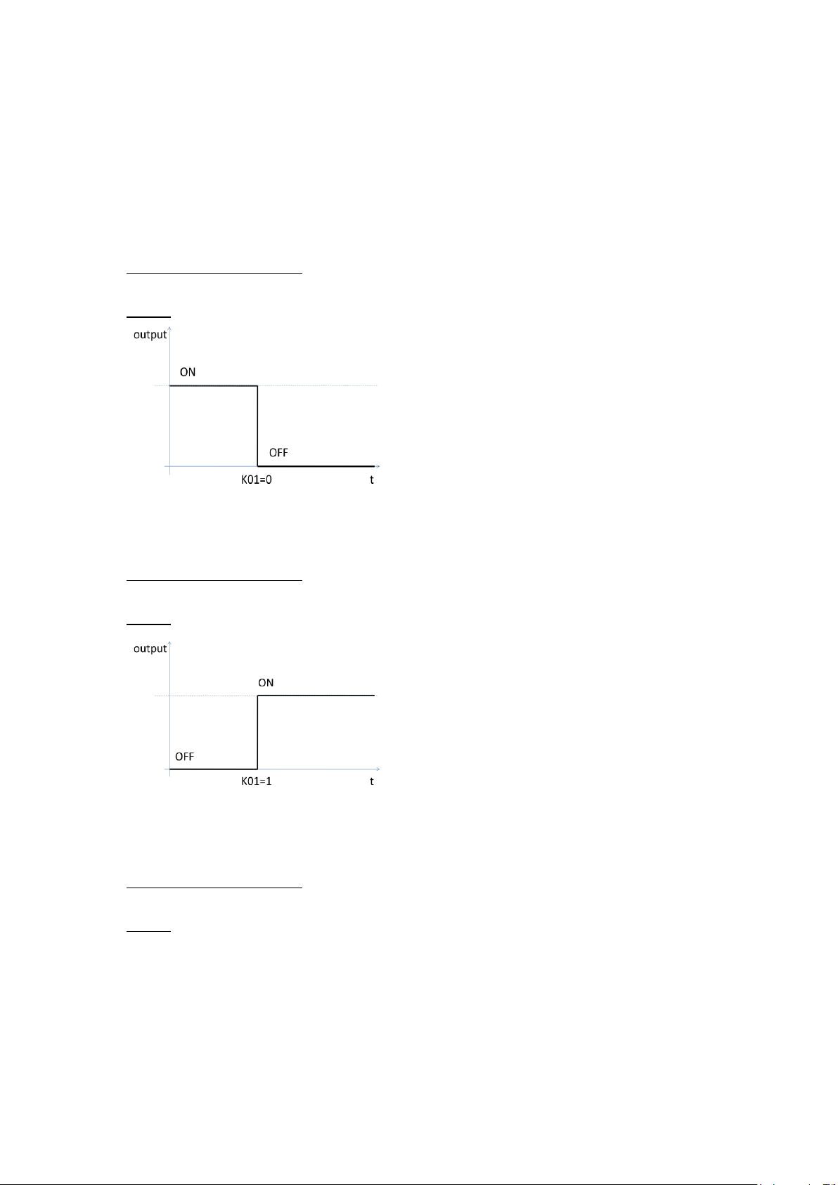
Normal ON/OFF/TOGGLE
Normal on/off/toggle operation changes the relay output status immediately after receiving
commands. No timing features included.
Switches
To switch off ch1 output:
Web access URL:
http://192.168.1.105/k01=0
Socket command text:
k01=0;
To switch on ch1 output:
Web access URL:
http://192.168.1.105/k01=1
Socket command text:
k01=1;
To toggle (opposite to previous status) ch1 output:
Web access URL:
http://192.168.1.105/k01=2
Socket command text:
k01=2;

www.BrickElectric.com
Timing Feature
NONE
Pulse ON/OFF/TOGGLE
Pulse on/off/toggle operation changes the relay output status immediately after receiving
commands, and wait for a predefined time period, then automatically switches to opposite
status.
Switches
To pulse on ch1 output, you can input by require web access:
Web access URL:
http://192.168.1.105/k01=3
Socket command text:
k01=3;
To pulse off ch1 output, you can input by require web access:
Web access URL:
http://192.168.1.105/k01=4
Socket command text:
k01=4;

www.BrickElectric.com
To pulse toggle (opposite to previous status) ch1 output:
Web access URL:
http://192.168.1.105/k01=5
Socket command text:
k01=5;
Timing Features
To set up customized timer for relay pulse outputs, timer T1 is used and need to be set.
Each relay channel has an independent timer K0xT1, timer supports from 1ms to
4294967295 second. K0xT1 needs to be set for time value, and K0xU1 needs to be set for
timer value unit. Default value for K0xT1 is 1000, and default unit for K0xU1 is ms.
To set timer T1 value to 5000:
Web access URL:
http://192.168.1.105/setpara[65]=5000
Socket command text:
setpara[65]=5000;
To set timer T1 value unit to ms:
Web access URL:
http://192.168.1.105/ setpara[29]=0
Socket command text:
setpara[29]=0;
To set timer T1 value unit to second:
Web access URL:
www.BrickElectric.com
http://192.168.1.105/ setpara[29]=1
Socket command text:
setpara[29]=1;
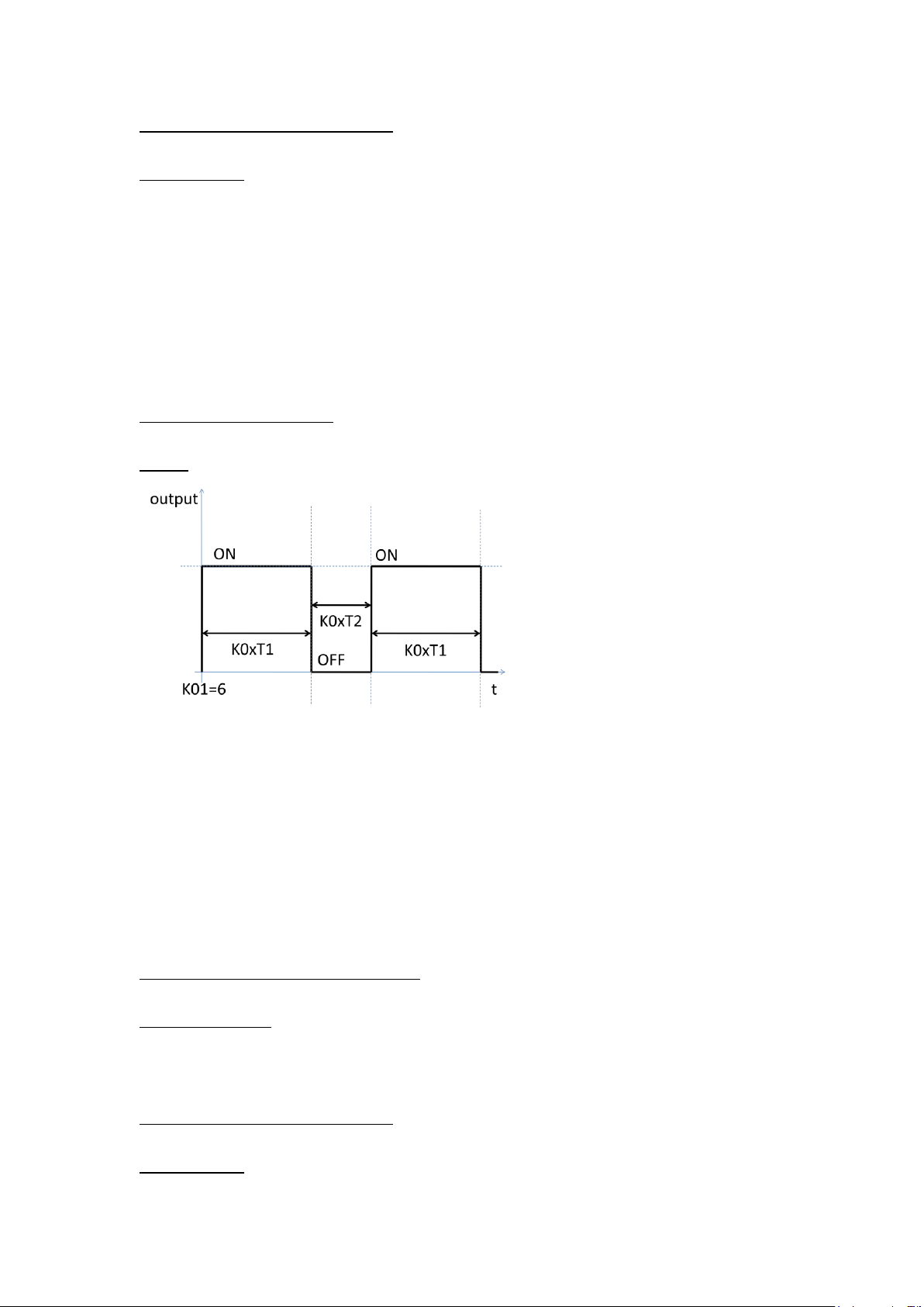
Cycle Switch Mode
Cycle switch mode changes the relay output status automatically on and off in customized
time period. After receiving cycle commands, relay output will always cycle until you give it
a new command.
Switches
To pulse off ch1 output, you can input by require web access:
Web access URL:
http://192.168.1.105/k01=6
Socket command text:
k01=6;
Timing Features
To set up customized timer for relay cycle outputs, timer T1 and T2 are used and need to
be set. Each relay channel has two independent timers K0xT1 and K0xT2, time period
supports from 1ms to 4294967295 second. K0xT1/K0xT2 is needed to be set for time
value, and K0xU1/K0xU2 is need to be set for timer value unit. Default value for
K0xT1/K0xT2 is 1000, and default unit for K0xU1/K0xU2 is ms.
To set timer T1 value to 5000:
Web access URL:
http://192.168.1.105/ setpara[65]=5000
Socket command text:
setpara[65]=5000;
To set timer T1 value unit to ms:
Web access URL:
http://192.168.1.105/ setpara[29]=0
Socket command text:
setpara[29]=0;

www.BrickElectric.com
To set timer T1 value unit to second:
Web access URL:
http://192.168.1.105/ setpara[29]=1
Socket command text:
setpara[29]=1;
To set timer T2 value to 5000:
Web access URL:
http://192.168.1.105/ setpara[66]=5000
Socket command text:
setpara[66]=5000;
To set timer T2 value unit to ms:
Web access URL:
http://192.168.1.105/ setpara[30]=0
Socket command text:
setpara[30]=0;
To set timer T2 value unit to second:
Web access URL:
http://192.168.1.105/ setpara[30]=1
Socket command text:
setpara[30]=1;
Read Switch Mode
Read current relay output status for feedback control. Module will return the current status
in web content or socket text, depending on how do you send the command.
To read relay ch1 current status:
Web access URL:
http://192.168.1.105/k01=7
Socket command text:
k01=7;
4.6 Password protection
Password protection function is used for protecting the device from un-authorized access.
Once enabled, user can only send effective command when they're able to provide correct
6-bit length access password.
In the following contents, assuming current IP Address is 192.168.1.105. And device
password is "123456", which is also the default password.
Enable/Disable Password Protection
To Enable password protection:

www.BrickElectric.com
Web access URL:
http://192.168.1.105/pwenable=1
Socket command text:
pwenable =1;
To Disable password protection, you need also firstly input correct password:
Web access URL:
http://192.168.1.105/ pw=123456&pwenable=0
Socket command text:
pw=123456&pwenable=0;
Change Password
To change password to "abcdef", you need also firstly input previous correct password:
Web access URL:
http://192.168.1.105/ pw=123456&newpw=abcdef
Socket command text:
pw=123456&newpw=abcdef;
4.7 Http port setting
In default conditions, HTTP port is always 80 if you enter directly in web browser a URL
without any additional parameters. But in some applications different port number is
needed for port forwarding or any other reasons. For example, you can force your web
browser to access http content at port 8080, to do so you need to enter http://url:8080.
This module is able to customize http access port to realize such functions. In the
following contents, assuming current IPAddress is 192.168.1.105.
Change Http Port
To change http port to 8080:
Web access URL:
http://192.168.1.105/ webport=8080
Socket command text:
webport=8080;
4.8 Hardware reset button
Hardware reset button is used for situations when you want to reset the device to factory
settings. For example, if you set incorrect IP Address and the device is no longer
detectable in your network. Two different level of reset are provided in this module.
Level-1 only reset parameters, i.e. network settings, time settings and so on, while Level-2
will reset on-chip app, i.e. for firmware updating/reload.

www.BrickElectric.com
Hardware reset Level-1 (Parameter reset)
To reset parameters, press the hardware reset button in above pictures until green and
red LEDs are both on, then release the button. Module will set all parameters to their
default values.
Hardware reset Level-2 (Firmware update/reload)
To update firmware, press the hardware reset button in above pictures until green and red
LEDs are both on, then continue to press the button for another 10 seconds. Module will
erase its firmware and try to download latest firmware from Internet. Please connect to
internet when you do this operation.
4.9 Identification & customized information
When more than one modules are installed in the field, it is necessary to be able to read
the identification information from module, for example serial number. Except for several
pre-defined parameters in system, additionally a device name which can be set by user is
supported.
Read serial number
You can read serial number by reading the sticker on the device, but you can also read
device serial number by communication.
To read device serial number:
Web access URL:
http://192.168.1.105/ getpara[100]=1;
Socket command text:
getpara[100]=1;
Customized device name
In some applications, customer may want to set up their own name for better identification
of the device. For this purpose, device name can be customized, with a maximum length
of 15 letters.
To read device name:
Web access URL:

www.BrickElectric.com
http://192.168.1.105/ getpara[97]=1;
Socket command text:
getpara[97]=1;
To change device name to "my_device":
Web access URL:
http://192.168.1.105/ setpara[97]=my_device
Socket command text:
setpara[97]=my_device;
Read device type
you can read device type by communication, for the purpose of better identification the
device.
To read device type:
Web access URL:
http://192.168.1.105/ getpara[99]=1;
Socket command text:
getpara[99]=1;
Read device firmware version
you can read device firmware version by communication, for the purpose of better
identification the device, or diagnosis.
To read device firmware version:
Web access URL:
http://192.168.1.105/ getpara[98]=1;
Socket command text:
getpara[98]=1;
4.10 Read Inputs
BEM107 has one input channel, which can detect external contact condition. It is not
allowed to apply any external voltage to those input channels. You can read the input
parameters to check if the external contact is closed or opened.
Read input condition
You can read input channel 1 by:
Web access URL:
http://192.168.1.105/ getpara[189]=1;
Socket command text:
getpara[189]=1;

www.BrickElectric.com
5. X-Connect
With X-Connect functionality, multiple BEM Series modules can be logically connected to
each other without using a central controller (for example, a PC or a server). You can
directly map any input channel of BEM Series I/O module to another output channel BEM
Series I/O module.
For example, if you have one BEM108 which have 8 inputs and four BEM104 which each
have 2 outputs and in total 8 outputs. In such a case you can map each input of BEM108
to the eight outputs of 4 BEM104 without central controller. Also, if you have 8 BEM107
which each have one input and in total 8 inputs, you can also map each of the input bit to
one or more output modules. This mapping is totally free, you can map the same one input
channel to 1 ~ 10 output channels at one output module or multiple output module.
When one input is mapped to one or more outputs, then if this input is triggered, all the
outputs that it mapped will also be triggered immediately.
5.1 X-Connect Map Setting
Each BEM Series module can support at max 10 I/O mapping. Each I/O mapping is
independent with each other. Each I/O mapping channel need to setup:
(1) Which input channel you want to map;
(2) Which module you want to map, that means IP address of the target module;
(3) Which output channel of target module you want to map;
For example, to setup BEM108 (IP: 192.168.1.105) input channel 1 to BEM104(IP:
192.168.1.106) output channel 1, all setting needed to be done at BEM108:
(1) Select input channel one in BEM108 by:
Web access URL:
http://192.168.1.105/ setpara[102]=1;
Or Socket command text:
setpara[102]=1;
(2) Select the module you want to map at 192.168.1.106 by:
Web access URL:
http://192.168.1.105/ setpara[133]=192;
Or Socket command text:
setpara[133]=192;
Web access URL:
http://192.168.1.105/ setpara[134]=168;
Or Socket command text:
setpara[134]=168;
Table of contents
Other BrickElectric Relay manuals


