manuals.online logo
Brands
  1. Home
  2. •
  3. Brands
  4. •
  5. Leviton
  6. •
  7. Relay
  8. •
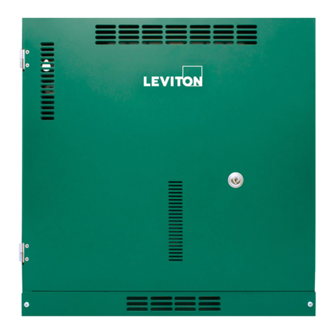
  9. Leviton EZ-MAX H Series User manual

Leviton EZ-MAX H Series User manual

EZ-MAX™ H SERIES - Lighting Control Panel Relays
Cat. No. RELAY
INSTALLATION INSTRUCTIONS ENGLISH
PK-A3453-10-00-0A
WARNINGS:
• TO AVOID FIRE, SHOCK OR DEATH: TURN OFF POWER AT CIRCUIT BREAKER OR FUSE AND TEST THAT
THE POWER IS OFF BEFORE WIRING!
• TO AVOID PERSONAL INJURY OR PROPERTY DAMAGE, DO NOT install to control a receptacle, or a load in
excess of the specified rating.
• Always disconnect the power supply from the panel's main board prior to making any connections between relay
boards and the main board. Failure to do so, may result in personal injury, damage to the panel, and void its warranty.
• To be installed and/or used in accordance with electrical codes and regulations.
• Must be installed by electrician or other qualified personnel.
• A disconnect switch or a circuit breaker must be provided and marked as the disconnecting device.
• The use of accessory equipment, not recommended by the manufacturer, may cause an unsafe condition.
CAUTIONS:
• If any emergency circuits are fed or controlled from this panel, they must be located electrically where fed. For
example, from a UPS, generator, or other guaranteed power source during emergency and power outage situations.
• If the equipment is used in a manner not specified by the manufacturer, the protection provided by the equipment
may be impaired.
• For indoor use only.
• DO NOT mount near gas or electric heaters.
• No user serviceable components. DO NOT attempt to service or repair.
• Use this device WITH COPPER OR COPPER-CLAD WIRE ONLY.
Product Description
H Series' relays are designed to be installed in EZ-MAX H Series panels only. Individual
relays of any type can be placed in any position in the panel. Two pole relays fit in the
same space as one pole relays.
Installing Individual Relay Cards
WARNING: TO AVOID FIRE, SHOCK OR DEATH, turn OFF power at circuit breaker or
fuse and test that the power is off before wiring.
1. Disconnect the low voltage control input plug, which is located at the top of the
main board.
2. Align the relay board in the desired relay position and insert the relay card plug
connector (male) into the socket (female) on the main board.
NOTE: Make sure all of the pins line up, and the connection is tight.
3. Insert and tighten the relay card mounting screw.
NOTE: Do not over tighten the relay card mounting screw with a high-amount of torque
force, as this can loosen the relay card plug connector.
EZ-MAX H Series Panel Interior
Connecting Lighting Loads
CAUTION: Prior to making any connections to the relay outputs, verify that none of the
loads have shorted. Failure to do so, may result in personal injury, damage to the panel,
and void its warranty.
1. Turn the power OFF.
2. Route the lighting system line and load leads through the high-voltage area of the panel.
3. Connect line and load leads for each lighting load to the output terminals of the
appropriate relay, as delineated in the project plans or panel load schedule. Space is
provided for the circuit identification number to be written adjacent to the terminals on
each relay card.
NOTE: If no panel load schedule exists, use the panel load schedule form supplied in the
clear plastic pocket inside the panel door to record the lighting circuit relay assignments,
while connecting the relay.
Photocell
Occupancy Sensor
Low Voltage Switch
Low Voltage Switch
with LED
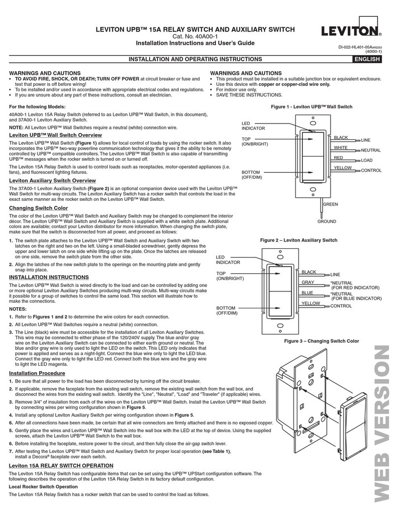
Connecting Low Voltage Input
Bring the low-voltage wiring for the contact inputs in through the knockouts in the low-
voltage wiring area. The EZ-MAX H Series relay card includes one input. The input is
software, which you can configure via programming to support momentary switches,
maintained switches (latching), motion sensors, or photocells. The input may be connected
prior to programming. Inputs may be connected to any terminal location, regardless of final
control programming. Connect contact closure input devices to the input terminals using
#18 AWG wire.
NOTE: Use the panel load schedule form, supplied in the clear plastic pocket inside the
panel door, to record the low voltage input types while making connections.
The Low Voltage Control diagrams, shown below, are for use with Leviton low-voltage input
devices ONLY.
Hot (Black)
Neutral (White)
Load
Blue
(Control)
Black
Red (24VDC)
Red
Blue
White
Black
White
Black
Red
Gray*
Blue
Blue
Blue Black
Black
Line
120/277/347V
AC
60Hz
Sensor
NC-Brown
NO-Brown/White
Common-Green
To HVAC
System
Gray*
Terminal Blocks
Switch
Common
Violet 1-10V Dim Out
Gray 1-10V Dim Out
Orange
Red
Black
Red
Black
Blue
Violet 1-10V Dim Out
Gray 1-10V Dim Out
Blue
Gray
Red
Black
White
Blue
Black
Blue
LOAD LOAD
Low Voltage Photocell
Occupancy Sensor
OPP20-RD3
N
H
ODC0P-D0W
© 2022 Leviton Mfg. Co., Inc.
What to do if...
A blinking green relay board status LED indicates that communication has not
been properly established for this card.
1. Power down the panel.
2.
Remove the relay card. Make sure the connectors on the relay card and on the main board are
not damaged.
3. Reinstall the relay card.
4. Power up the panel, see if the LED light stopped blinking, and verify the relay card can
be seen through the controller.
The relay does not turn ON.
1. If the load was removed, check the continuity of the relay terminal blocks.
a. If the green relay board status LED is ON, make sure there is resistance.
b. If the green relay board status LED is OFF, make sure there is no resistance.
2. Verify the supply breaker is ON and energized.
3. The relay contact may be damaged.
The relay does not turn OFF the load.
1. If the load was removed, check the continuity of the relay terminal blocks.
a. If the green relay board status LED is ON, make sure there is resistance.
b. If the green relay board status LED is OFF, make sure there is no resistance.
2. Relay contact may have been welded shut.
3. Circuit from supply breaker may be wired in parallel to load.
Relay Specifications
Characteristics Load Ratings
SCCR
Type Poles VAC Tungsten Elec.
Ballast
Magnetic
Ballast
Motor
Rating
RELAY-L3H
Latching 1
120 20A 16A 30A 1 HP
18 kA
277 N/A 16A 30A N/A
347 N/A 20A N/A N/A
RELAY-2PH
Elec. Held,
N.O.
2
208
N/A N/A 20A 2 HP 14 kA
240
480
General Specifications
Type Description
Operating Voltages RELAY-L3H: 120V, 277V, 347V AC (50/60 Hz)
RELAY-2PH: 208V, 240V, 480V AC (50/60 Hz)
Class 2 Output Rating 8-Relay: 24VDC, 150mA (Max. 300mA)
24-Relay: 24VDC, 150mA (Max. 900mA)
Class 2 Terminal Wire Size: 14, 16, 18, 20, 22 AWG
Recommended Tightening Torque: 0.45 N-m (4 in-lb)
Status Indicators Green: Indicates relay is in the closed position.
Red: Depends on the input that is programmed.
Operating Environment 32°-112°F (0°-50°C)
Relative humidity (non-condensing): 10%-90%
Inrush Withstand 500 A @ 2 ms
Dimensions 1.635" W x 5.5" L (41.28 mm W x 139.7 mm L)
Mounting
Mounts inside an EZ-MAX H Series panel
Pre-drilled mounting hole for securing relay card
Individual relay cards - 1P and 2P are equal size
Control Input Device Types
Low-voltage switches - Momentary or maintained style,
Pilot light indicator support
Occupancy sensor - Three-wire, 24VDC
Daylight sensor -Three-wire 24VDC
FCC STATEMENT
This equipment has been tested and found to comply with the limits for a Class B digital device, pursuant to part 15 of the FCC Rules. These limits are designed to provide reasonable
protection against harmful interference in a residential installation. This equipment generates, uses and can radiate radio frequency energy and, if not installed and used in accordance
with the instructions, may cause harmful interference to radio communications. However, there is no guarantee that interference will not occur in a particular installation. If this equipment
does cause harmful interference to radio or television reception, which can be determined by turning the equipment off and on, the user is encouraged to try to correct the interference by
one or more of the following measures:
• Reorient or relocate the receiving antenna.
• Increase the separation between the equipment and receiver.
• Connect the equipment into an outlet on a circuit different from that to which the receiver is connected.
• Consult the dealer or an experienced radio/TV technician for help.
IC STATEMENT
This device complies with Industry Canada licence-exempt RSS standard(s). Operation is subject to the following two conditions: (1) this device may not cause interference, and (2) this
device must accept any interference, including interference that may cause undesired operation of the device.
FCC SUPPLIERS DECLARATION OF CONFORMITY (sDoC): RELAY product with responsible party Leviton Manufacturing, Inc., 201 N Service Road, Melville, NY, www.Leviton.com.
This device complies with part 15 of the FCC Rules. Operation is subject to the following two conditions: (1) This device may not cause harmful interference, and (2) this device must
accept any interference received, including interference that may cause undesired operation.
Any changes or modifications not expressly approved by Leviton Manufacturing Co., could void the user’s authority to operate the equipment.
For Technical Assistance Call: 1-800-824-3005 (USA Only) or 1-800-405-5320 (Canada Only) www.leviton.com
LIMITED 5 YEAR WARRANTY AND EXCLUSIONS
Leviton warrants to the original consumer purchaser and not for the benefit of anyone else that this product at the time of its sale by Leviton is free of defects in materials and workmanship under
normal and proper use for five years from the purchase date. Leviton’s only obligation is to correct such defects by repair or replacement, at its option. For details visit www.leviton.com or call
1-800-824-3005. This warranty excludes and there is disclaimed liability for labor for removal of this product or reinstallation. This warranty is void if this product is installed improperly
or in an improper environment, overloaded, misused, opened, abused, or altered in any manner, or is not used under normal operating conditions or not in accordance with any
labels or instructions. There are no other or implied warranties of any kind, including merchantability and fitness for a particular purpose, but if any implied warranty is
required by the applicable jurisdiction, the duration of any such implied warranty, including merchantability and fitness for a particular purpose, is limited to five years. Leviton is
not liable for incidental, indirect, special, or consequential damages, including without limitation, damage to, or loss of use of, any equipment, lost sales or profits or
delay or failure to perform this warranty obligation. The remedies provided herein are the exclusive remedies under this warranty, whether based on contract, tort or otherwise.
FOR CANADA ONLY
For warranty information and/or product returns, residents of Canada should contact Leviton in writing at Leviton Manufacturing of Canada ULC to the attention of the Quality
Assurance Department, 165 Hymus Blvd, Pointe-Claire (Quebec), Canada H9R 1E9 or by telephone at 1-800-405-5320.
Patents covering this product, if any, can be found on www.leviton.com/patents.
LEVITON, the Leviton logo, and EZ-MAX are trademarks of Leviton Manufacturing Co., Inc.
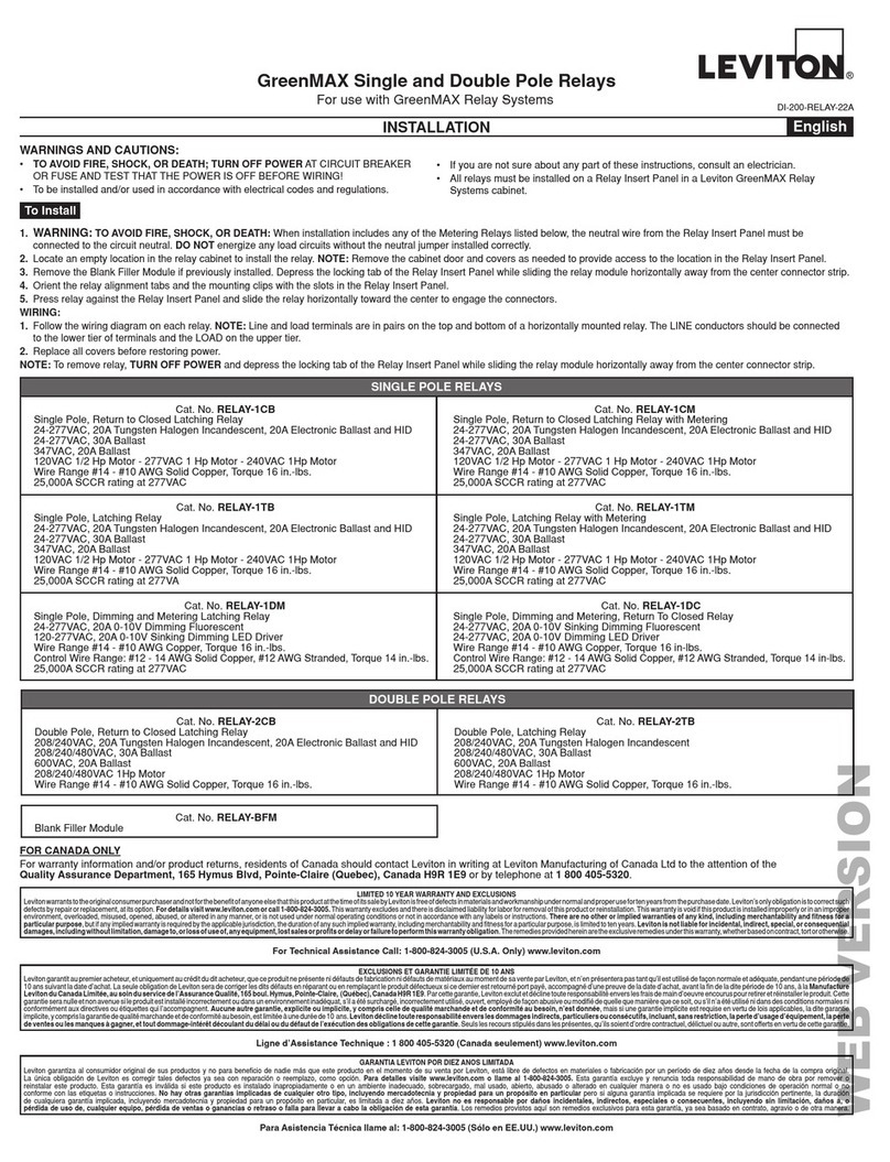
Other manuals for EZ-MAX H Series

2

This manual suits for next models

2

Other Leviton Relay manuals

Leviton GreenMAX R16TC-100 User manual

Leviton

Leviton GreenMAX R16TC-100 User manual

Leviton GreenMAX R16TC-100 User manual

Leviton

Leviton GreenMAX R16TC-100 User manual

Leviton GreenMAX Series User manual

Leviton

Leviton GreenMAX Series User manual

Leviton EZ-MAX Plus 8 User manual

Leviton

Leviton EZ-MAX Plus 8 User manual

Leviton EZ-MAX Plus 16 User manual

Leviton

Leviton EZ-MAX Plus 16 User manual

Leviton WSP05-010 User manual

Leviton

Leviton WSP05-010 User manual

Leviton EZ-MAX User manual

Leviton

Leviton EZ-MAX User manual

Leviton GreenMAX R1616-1CB User manual

Leviton

Leviton GreenMAX R1616-1CB User manual

Leviton GreenMAX Relay System Cabinet User manual

Leviton

Leviton GreenMAX Relay System Cabinet User manual

Leviton GreenMAX RELAY-1TB User manual

Leviton

Leviton GreenMAX RELAY-1TB User manual

Leviton Z-Max Remote Installation and operating instructions

Leviton

Leviton Z-Max Remote Installation and operating instructions

Leviton Z-MAX r24sd User manual

Leviton

Leviton Z-MAX r24sd User manual

Leviton EZ-Max Plus Operating instructions

Leviton

Leviton EZ-Max Plus Operating instructions

Leviton EnOcean WSPAS-LV4 User manual

Leviton

Leviton EnOcean WSPAS-LV4 User manual

Leviton 40A00-1 Mounting instructions

Leviton

Leviton 40A00-1 Mounting instructions

Leviton EZ-Max Plus Operating instructions

Leviton

Leviton EZ-Max Plus Operating instructions

Popular Relay manuals by other brands

Banner ES-TA-3D1 manual

Banner

Banner ES-TA-3D1 manual

Thytronic NV10P manual

Thytronic

Thytronic NV10P manual

Honeywell 7800 SERIES installation instructions

Honeywell

Honeywell 7800 SERIES installation instructions

Rockwell Automation Allen-Bradley Guardmaster GLP quick start guide

Rockwell Automation

Rockwell Automation Allen-Bradley Guardmaster GLP quick start guide

Siemens SIPROTEC 7SJ600 instruction manual

Siemens

Siemens SIPROTEC 7SJ600 instruction manual

Siemens SIMPRO-100 instruction manual

Siemens

Siemens SIMPRO-100 instruction manual

WEG RNW Series installation instructions

WEG

WEG RNW Series installation instructions

Siemens SIRIUS 8WD44.0-0EA2 Original operating instructions

Siemens

Siemens SIRIUS 8WD44.0-0EA2 Original operating instructions

ABB CIRCUIT SHIELD 49/50/51 instructions

ABB

ABB CIRCUIT SHIELD 49/50/51 instructions

LOVATO ELECTRIC SRATH21 installation manual

LOVATO ELECTRIC

LOVATO ELECTRIC SRATH21 installation manual

F&F 5908312592389 quick start guide

F&F

F&F 5908312592389 quick start guide

Broyce Control P9650 quick start guide

Broyce Control

Broyce Control P9650 quick start guide

Siemens 3TX7014 operating instructions

Siemens

Siemens 3TX7014 operating instructions

KAEL Muhendislik Elektronik VARkombi-12-PC-TFT-OG-SOLAR manual

KAEL Muhendislik Elektronik

KAEL Muhendislik Elektronik VARkombi-12-PC-TFT-OG-SOLAR manual

Novatek-electro REV-120 operating manual

Novatek-electro

Novatek-electro REV-120 operating manual

Circutor CBS-4 Series manual

Circutor

Circutor CBS-4 Series manual

Basler BE1-27 instruction manual

Basler

Basler BE1-27 instruction manual

ASO Safety Solutions ELMON classic 32-312 Brief Instruction

ASO Safety Solutions

ASO Safety Solutions ELMON classic 32-312 Brief Instruction

manuals.online logo
manuals.online logoBrands
  • About & Mission
  • Contact us
  • Privacy Policy
  • Terms and Conditions

Copyright 2025 Manuals.Online. All Rights Reserved.