Bridge City Signature Series User manual


Contents
1.Overview..............................................................................................................................................2
2.Unpacking........................................................................................................................................... 6
3.Asemblying.........................................................................................................................................6
4.Operation............................................................................................................................................ 7
5.Calibrating the Perpendicularity and Parallelism ................................................................ 12
6.Maintenance..................................................................................................................................... 13
7.Trouble-shootings.......................................................................................................................... 14
8.Exploded View and Parts List..................................................................................................... 15
1.概述.................................................................................................................................................... 18
2.拆包.................................................................................................................................................... 20
3.安装.................................................................................................................................................... 20
4.操作.................................................................................................................................................... 21
5.锯片垂直度及相对于台板运动平行度的校准................................................................................ 25
6.保养.................................................................................................................................................... 26
7.常见问题............................................................................................................................................ 27
8.爆炸图和零件清单............................................................................................................................ 28

1
English Version

2
Thank you for your purchase of the JMPv2
Jointmaker Pro!
Your experience with this innovative new tool
should be nothing but positive. Towards that
objective, we are asking you to contact us with any
questions regarding assembly or use of the
Jointmaker Pro. You may reach Harvey Industries
by:
https://www.harveywoodworking.com
You may also visit Bridge City Tool Work's by:
https://bridgecitytools.com
PLEASE NOTE: This is a moderated forum and we
do our best in keeping it positive, exciting, and a
useful resource.
1. OVERVIEW
The Jointmaker Pro is the world's first stationary
hand crosscut saw and will accurately allow you to
make most of the cuts required in wood joinery plus
a myriad of other sawing applications.
Consisting primarily of two independent linear
tables mounted over specially designed,
fine-toothed saw blades, the Jointmaker Pro
redefines the meaning of "cut by hand”. Using no
electrical power, the Jointmaker Pro is designed
specifically to make precision cuts for the most
demanding craftspeople with as little noise as
possible, and without the need for dust collection.
Understanding how this tool works—what it can
and cannot do—is your key to a successful and
fruitful experience.
Cutting wood accurately by hand requires a great
deal of practice, a well-made saw with sharp teeth
and yet still remains difficult for many, particularly
those new to the craft or those with disabilities.
With the Jointmaker Pro, people of all ages and
experience levels can achieve results that are
MORE ACCURATE than cuts made with power
equipment. Furthermore, the cuts are unparalleled
in quality creating opportunities for new and
exciting ideas not possible with traditional
techniques.
At this time, please take a few minutes and peruse
the assembly section of this guide to become
familiar with the nomenclature of the Jointmaker
Pro. This will make the remainder of this section
much easier to understand.
FEATURES AND SPECIFICATION
Max. Cutting Height 1-5/8"
Blade Tilting ±45°
Sliding Table Size 10-1/2"x8"
Sliding Table Travel 15"
Trap Fence Size 16-1/8"x1-15/16"x3/4"
(Bevel 10°)
Straight Fence Size 14-1/8"x3-1/2"x3/4"
Fence Dovetail Size Trapezoidal Waist Angle
72°
Depth 0.29”
Trapezoidal Short Side
0.31”
Trap Jaw Size 3-5/8"x1-3/4"x1-3/4"
Blade Pitch increment 0.05" in one turn
0.05" in one turn
30-1/2"x13-45/64"x13-7/64"
Blade Height increment
Overall Size
Net Weight 35 Lbs
Keel
Fence Lock Knob Blade
Fence
Blade Height
Adj. Handle
Blade Pitch Adj. Knob
Trap Jaws
Table
Keel Lock Knob

3
SAFETY
Your Jointmaker Pro is no different than any other
sharp tool—usecommonsense!
Although it may seem safe to take risks because
the saw blade is stationary—and the only motion is
provided by YOU —safety should never be taken
for granted.
Etched on the top of each sliding table is a graphic
element that is designed to remind you of the risk
to your fingers. It may seem obvious, but we
strongly recommend keeping your fingers out of
this zone, especially when the blade is tilted.
After you have spent an hour or two using the
Jointmaker Pro we hope you share your new found
ability with other members of your family—this tool
can be enjoyed by many who like making gallery
quality cuts in a noise free environment!
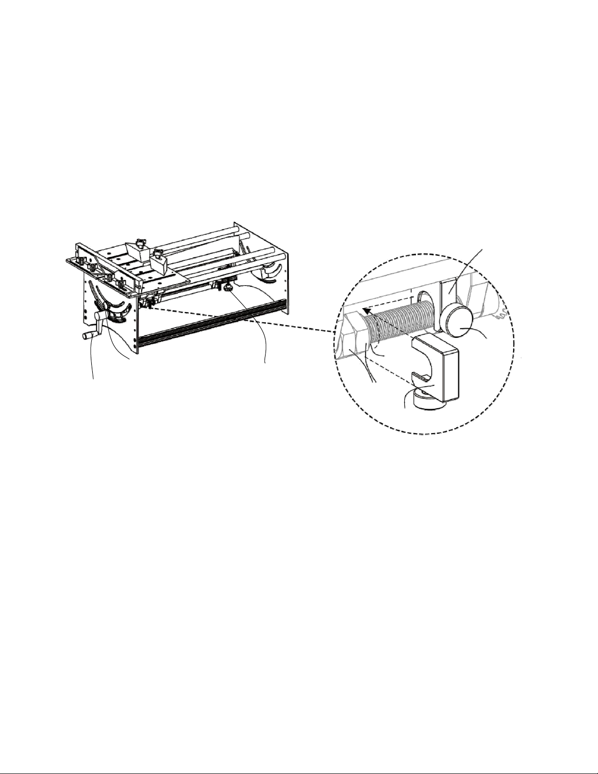
SAW RIGIDITY AND ERGONOMICS
Under all circumstances, the Jointmaker Pro needs
to be firmly anchored to a work surface or attached
to a stand. If the saw moves while cutting your
accuracy and enjoyment of the tool will be less than
optimal.
The front table height of the Jointmaker Pro should
be an inch or so below your belt line. At this height,
you will be able to make a full stroke without undue
stress on your back or arms. If possible we
recommend that the rear of the Jointmaker Pro be
approximately three inches higher than the front.
This incline shortens the stroke of your arms,
increases your ability to see your work and reduces
strain on your lower back during long work
sessions.
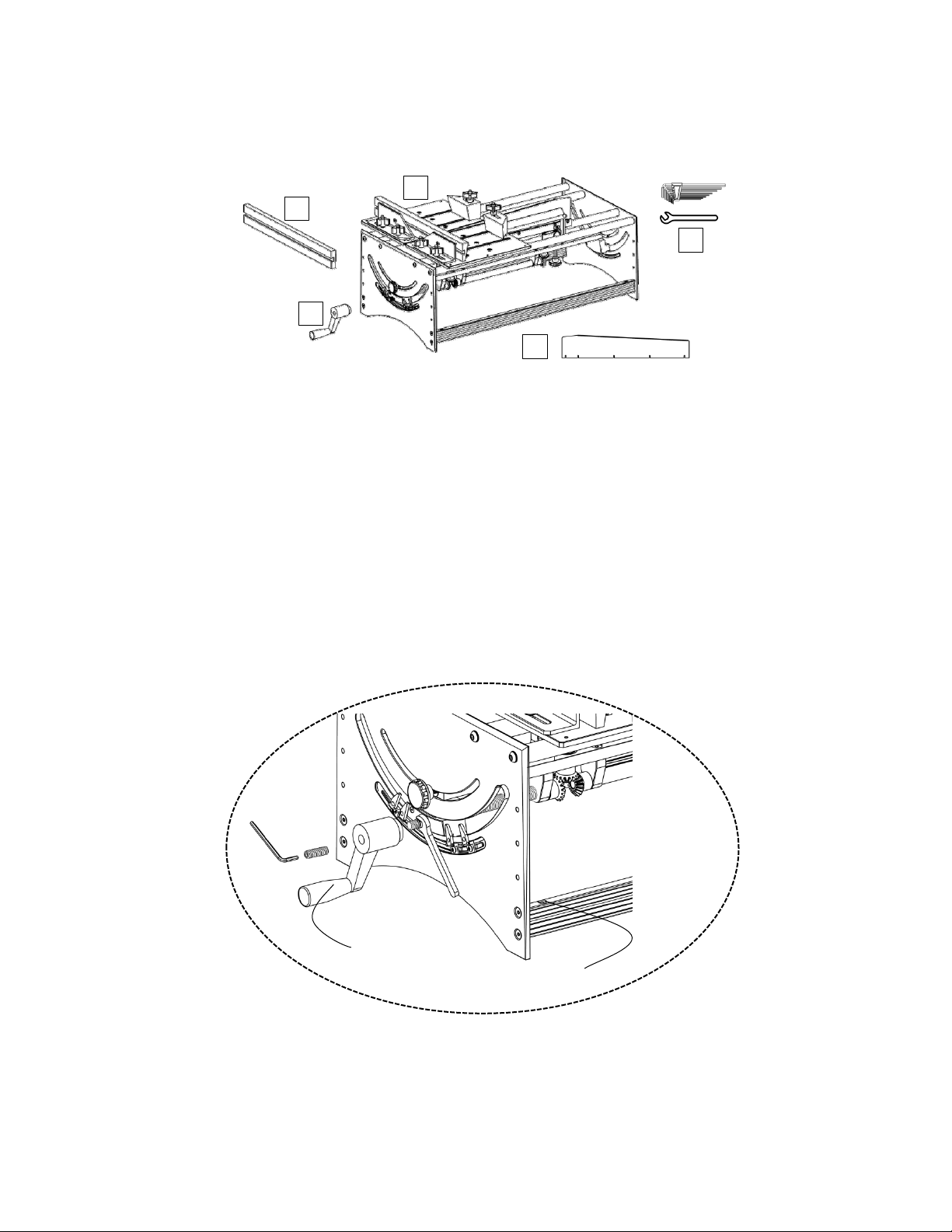
WORK HOLDING REQUIREMENTS
Traditionally when cutting wood with a hand saw
you clamp the material to be cut to a workbench or
hold your stock in a vise. With either method, the
stock should always be firmly anchored in order to
achieve optimal, and accurate, results.
The same work holding requirements are true
when making most cuts with the Jointmaker Pro.
The sliding table is analogous to a workbench
surface and the angled trap clamps act as a vise.
These elements become particularly crucial with
the Jointmaker Pro because unlike any other hand
sawing experience, you are cutting from the bottom
up as opposed to top down. Without your stock
firmly anchored to the sliding tables, the negative
feed (the tendency of the wood to ride up over the
top of the blade) becomes difficult to manage with
hand strength alone. In almost all cases, we
strongly recommend that you utilize these work
holding aids for accuracy and blade longevity.
When using the blade in a tilted position, trap
clamping is mandatory.
SAW BLADES & DEPTH OF CUT
All of the saw blades currently designed for the
Jointmaker Pro contain between 350 and 460 teeth
over their length. Because the blade is inclined (the
front of the blade is lower than the back of the
blade) in relation to the table surfaces, each tooth
bears the exact same workload.
For example, a piece of walnut with a 1/2”x1/2”
cross-section can be cut in half with one stroke
using the standard crosscut blade. To correctly set
the blade for this cut, you would adjust the blade so
that the first couple of teeth are below table height,
and the last tooth of the saw blade is set with the
pitch adjustor to approximately 1/32 ’above the
stock of the wood. With the stock held firmly
against the fence, one stroke and the cut is
complete, smooth and accurate. See the Cutting
Guide page 6 for more details.
This example is possible because the standard
JMP crosscut blade has approximately 400 teeth.
Using the stock and set-up described above, each
tooth of the saw has a chip load of just over one
one-thousandth of an inch (.5/400 = 0.00125n). It is
the combination of the chip load, precise linear
movement and blade rigidity that makes
Jointmaker Pro cuts unparalleled in quality or
accuracy.

4
For wider stock (where more teeth are
simultaneously engaged with the stock), multiple
passes are required utilizing a smaller depth of cut
per pass.
For example, 1/2”thick walnut 4”in width would
dictate that you set the saw up with the first couple
of teeth below table height (using the hand crank at
the front of the JMP) and the last tooth
approximately 1/16 ”above the table (using the
Pitch Adjustor). With this set-up, it will take 10
passes to cut the stock in half. Between each pass
the blade is raised approximately 1/16". In this
situation, the 400 teeth are required to cut
approximately 1/16th of material per pass. The chip
load is now one ten-thousandth of an inch
(.0625/400) per tooth! However, because the board
is 4”in width, more teeth are engaged during each
pass creating more resistance. More resistance
requires smaller bites for the cuts to feel almost
effortless.
The only "guide”we can provide for tailoring your
technique to accommodate the myriad of different
species and sizes of wood is to emphasize that the
effort required to cut any wood should be minimal.
Harder material or wider stock requires smaller
bites and more passes. If you are overly
aggressive, you will dramatically shorten blade life
and the quality of your cuts will suffer. After a short
"getting acquainted”period all of this will become
second nature.
As a reference, one full revolution of the crank
handle raises the blade exactly .055 ”or slightly
less than 1/16 ”. You will discover that extremely
dense woods will require blade height adjustments
as small as 1/8 of a revolution between cuts and
some softwoods can be cut with 3 full revolutions
for each pass! It is your job to discover the optimal
settings for ease of use according to your own
preferences and applications.
You will soon discover the general purpose
cross-cut blade that ships with the JMP will do the
majority of cuts (.4mm x 28). The 16 teeth per inch
rip blade is useful for cutting tenons and dovetails if
you have many to cut. The .3mm crosscut is ideal
for small stock but does not track well in deep cuts
(it is so thin it will follow the density changes of the
wood being cut).
You will know when your blade is dull because of
the resistance you sense with cutting or the quality
of the cut is not smooth to the touch. Blades are not
designed to be sharpened —they are disposable.
Contact your local distributor to avail of
replacement blades.
THE FENCES AND HAND PLACEMENT
The Jointmaker Pro utilizes two fences that are
normally bridged by a sacrificial wooden fence. The
only time you do not use both tables is when you
are cutting face miters.
There are two sacrificial fences, one is straight and
the other has an angled face. Use the straight
fence for joinery and the trap fence for crosscuts.
Werecommendthefencesbelockedinthe
forward position for all cuts of 4”or less in width.
For stock wider than 4 inches, slide the fences to
the back position.
When possible, your hands should be directly over
the center of the dovetailed ways on each side of
the saw blade. As your experience with the saw
grows, you will learn that you can use one hand to
make your strokes and the other will be raising the
blade on the return stroke. This combination is
efficient and fast.
We recommend that your first cuts be made with
both hands employed during the sawing strokes.
NOTE: The table tops are orange for a reason; you
can write on them with a pencil. For example, once
you have the fence set to 90 degrees, you can
scribe a pencil line along the fence and use this line
as a reference.
MISTAKES WE HAVE MADE
We have ruined several blades because of human
error. Please review this section to learn from our
mistakes.

5
•MAKE SURE THE KEEL, THE FENCES, AND
YOUR CLAMPS are all TIGHT before sawing.
This will eliminate 80% of the mistakes we have
made.
•Lower the blade below table height after each
session. Horizontal surfaces attract things, and the
blades are easily damaged with contact by metal
objects or heavy wood.
•It is helpful to have an old toothbrush nearby to
periodically clean wood fibers that may be
embedded in the gullets of the blade. This is
particularly helpful when using the rip blade.
•Lastly, enjoy the fact that you are the motor. Let
the saw do the work and use as many passes as
needed to accomplish your tasks. We
GUARANTEE that aggressive sawing techniques
are going to be expensive for you.
WARRANTY
Your Jointmaker Pro is fully warranted for defects
in workmanship. Please notify your local distributor
immediately if you have encountered a defective
component so it can be replaced immediately
LUBRICATION
Please review the lubrication guide on page 6 for
all the lubrication locations (this is done once or
twice a year depending on use.) We recommend
using the lubrication included with your Jointmaker
Pro.
YOUR FIRST CUT
Once your Jointmaker Pro is properly set-up, you
are ready to make your first cut.
We recommend practicing your first cut on a small
dowel rod, 1/4 ”一1/2” in diameter. Set the
leading edge of the crosscut blade slightly below
table height, and using the pitch adjustor, raise the
rear of the blade until it is slightly taller than your
stock.
Beforeyoumakeacut,takeacoupleof"dryruns”
to get a feel for the resistance of the tables in
motion. When comfortable, hold your material
firmly against the fence and with one smooth,
controlled push, cut your stock. You will discover
after just a few passes the rhythm required for
incredible results. As the density/ width of your
stock changes, you will sense the need to reduce
depth of cut and increase the number of passes.
THERE ARE NO GUIDELINES other than the
feedback you sense from the cutting action will
dictate any adjustments you will need to make for
effortless cutting.
Thank you again for your purchase of the
JMPv2 Jointmaker Pro. Please share pictures
and stories with us as you employ this remarkable
new tool in your shop!

6
2. Unpacking
Your Jointmaker Pro is carefully packaged for safe transportation. Remove the packaging materials around
it and inspect by Fig.1 and below list. If you discover that the product is damaged or any parts
missed,please immediately call your distributor or Customer Service for advice.
Fig. 1
3. Assembling
The Jointmaker Pro has been almost assembled in factory, all you need to do is completing the following
two steps:
1. Install the blade height adjustment handle, as shown in Fig. 2.
Fig. 2
2. Fix the Jointmaker Pro to the stand or any other platforms by using the included M5x80 hex bolt, M5 nut
and washer through the mounting hole.
1 Main Body
2 Blade Height Adjustment Handle
3 Straight Fence (Trap Fence has been pre-installed.)
4 Hardware Package (Hex Wrenches x 1 Set, Open-end Wrench x 1)
5 Crosscut A‒28tpi x 2 (One has been pre-installed.)
6 Lubrication x1 (not shown in Fig.1)
7 Instruction Manual x1 (not shown in Fig.1)
1
2
5
4
3
Mounting Hole
Blade Height Adj. Handle

7
4. Operation
Note: This chapter states the basic operation of Jointmaker Pro. However, before the formal use, the
Jointmaker Pro must be calibrated referring to Chapter 5 to ensure its high accuracy and excellent
performance.
4.1 Adjusting the Blade Height (Fig. 3)
As shown in Fig.3, rotate the blade height adjustment handle until you get desired blade height. For each
turn of the handle clockwise or counterclockwise, the overall height of the blade will increase or decrease by
1.25mm.
Note: To prevent the keel being rotated while rotating the blade height adjustment handle for high cutting
accuracy, the front and rear keel lock knobs must be tightened (the rear keel lock knob is not shown in Fig.3)
before adjusting the blade height.
Fig. 3
Adjusting the blade height stop (Fig. 3)
The Jointmaker Pro is equipped with a height stop to prevent the lead screw being damaged while lifting.
The lowest and highest positions of the stop has been set at factory. To operate repeatable cutting by
certain height, adjust the highest position of the stop as following steps:
1. There are three nuts on the front shaft, the two closest to the front plate are jam nuts (need no
adjustment) and the third nut that can be adjusted for different height requirements receives the height stop.
2. With the blade at the desired height and pitch, attach the Height Stop as illustrated. The top of the Height
Stop should be flush against the bottom of the keel and fully embrace the nut. Tighten Lock Knob. Blade
height will now repeat.
Note:
1. Before any cutting operations, the starting position of blade must be under the table, that’s why the
lowest position of the height stop has been set at factory and should not be adjusted in any circumstance.
2. Be careful when turning the blade height adjustment handle, too much force can cause the bevel gears
to strip after the blade spin has reached the max./min. Height (or if there are any binding issues).
3. If the red height stop is removed, then please be aware that the orange blade holder can come into
contact with the top/bottom of the keel assembly and potentially damage the keel if not properly operated.
Washer
Jam Nuts
Height Stop
Lock Knob
Height Stop
Blade Pitch Adj. Knob
Blade Height Adj. Handle
Front Keel Lock Knob

8
4.2 Adjusting the Blade Pitch (Fig. 3)
As shown in Fig.3, you can adjust the blade pitch by turning the blade pitch adjustment knob. (The Blade
Pitch increment of one turn is 0.05”)
Note:
1. If the pitch was set too aggressive, you may get your material stuck on the blade , which may ruin the
blade. When this happens, do not attempt to retract the stock by moving the tables backwards, try lowering
the blade directly out of the cut.
2. The very best practice is to start with a pitch that is too low and gradually increase it to an optimal pitch.
Please refer to the Cutting Guide on page 6 for more details.
3. The front blade teeth must be lower than the table while adjusting the blade pitch.
4.3 Adjusting the Blade Angle (Fig. 4)
Loosen the two keel lock knobs (the rear keel lock knob not shown in Fig.4), grasp the middle of keel and
swing to get the desired blade angle, then tighten the two keel lock knobs.
Note:
1. Before any cutting operations, make sure that the blade whose angle is adjusted will not interfere with
the fence.
2. After each adjustment of the blade angle, the parallelism between the blade and table travel should be
inspected and calibrated according to the following steps:
a. Position a hex key wrench (or a hard card) against the fence. Lightly touch the end of the wrench to the
leading edge of the saw blade (as illustrated in Fig. 8).
b. Slide the table slowly, inspect the parallelism between the blade and table travel.
c. If any deviation in parallelism occurs, slightly loosen the keel lock knob on the deviation side, and slightly
tap the keel to complete the adjustment of the parallelism.
Fig. 4
Quick angle position stop
There are four quick angle position stops below the dial which are used to locate the common angles
quickly. Loosen the position stop lock screws by a hex wrench, the position blocks can be slid to desired
angles, then tighten the lock screws. When the position blocks are not needed, flip them down.
Position Stop Lock Screws
Acrylic Cursor
Quick Angle Position Stops x 4
Hex Countersunk Head Screw
Middle of Keel
Front Keel Lock Knob

9
4.4 Replacing the Blade (Fig. 5)
When the blade teeth is offset, blunt, or worn, replace the blade as follows:
1. Loosen the Light Grey Saw Guide by a hex wrench (The Black Guide is never adjusted--it is a reference
surface.) and release the five blade lock screws, remove the old blade and replace with a new one.
2. Tighten the five blade lock screws from front to back.
3. Force the Light Grey Saw Guide to keep it tightly close to the blade, then tighten the Light Grey Saw
Guide lock screws.
Fig. 5
Note: Blades are not designed to be sharpened—they are disposable. Contact your local distributor to avail
of replacement blades.The blade that ships with the JMP is Crosscut A‒28tpi, and there are also another
three types of blade available for your additional needs. Please refer to the following table for detailed
information.
4.5 Using the Trap Jaws
It is the most important aspect for repeatable results. Because the saw is cutting from the bottom up, you
are fighting negative feed—this is the tendency of the board to move upward resisting the cut. This upward
tendency needs to be completely eliminated with proper work holding. It is particularly critical when the
blade is tilted. If the stock move upward while the blade is tilted, you will almost always jam your stock on
the blade. Not good.
The trap jaws can be used to fix the workpiece quickly. The clamping location of trap jaw can be adjusted by
changing the fixing slot. The side of trap jaw is a bevel, which can force the workpiece from two directions
for a better clamping.
Crosscut A‒28tpi Crosscut B‒32tpi Crosscut C‒28tpi Rip Blade‒16tpi
Blade Length 419mm 419mm 419mm 419mm
Blade Width 74mm 74mm 74mm 74mm
Blade Thickness 0.4mm 0.3mm 0.4mm 0.4mm
Kerf Thickness 0.4mm 0.3mm 0.58mm 0.4mm
Blade Lock Screw
Light Grey Saw
Guide Lock Screw Light Grey Saw Guide

10
4.6 Adjusting and Replacing the Fence (Fig. 6)
1. Loosen the four fence lock knobs, the fence can be swung and moved forward and backward to meet the
needs of multiple cutting.
2. Raise the blade to the highest position, Erect the square (A) with its two sides against the table and
blade respectively. Inspect and calibrate the perpendicularity between the fence and table. If any deviation
in perpendicularity occurs, loosen the four fence lock knobs and adjust their position until the deviation
disappears.
3. The fence can be removed and replaced by loosing the two fence lock screws.
Tra
p
Jaws
Fence Lock Screws Tra
p
Jaw Lock Knobs
Fence Lock
Knobs Fence

11
4.7 Cutting Guide
Use the following guidlines to determine the working relationship between blade pitch, material length and
material density. These three variables determine the number of full (or partial) cranks required for a
through cut.
Generally speaking, the smaller the cross-section the greater the pitch. As the cross-section lengthens,
pitch decreases and the number of strokes and crank revolutions increases to complete the cut.
Material:Walnut
Cross-Section:1/2" x 1/2" (13mm x 13mm)
Blade Pitch: 17/32" (13.5mm)
Crank Revolutions between Strokes: 0
Number of Strokes: 1
Material:Rosewood
Cross-Section:1/2" x 1/2" (13mm x 13mm)
Blade Pitch: 11/64' - 3/16"" (4-5mm)
Crank Revolutions between Strokes: 3
Number of Strokes: 3-4
Material:Walnut
Cross-Section:1/2" x 3" (13mm x 76mm)
Blade Pitch: 1/16" (1.5mm)
Crank Revolutions between Strokes: 1
Number of Strokes: 10-12
Material:Rosewood
Cross-Section:1/2" x 3" (13mm x 76mm)
Blade Pitch: 1/32" (1mm)
Crank Revolutions between Strokes: 1/2
Number of Strokes: 18-22
EXAMPLE 1
EXAMPLE 2
EXAMPLE 3
EXAMPLE 4
First couple of teeth are always BELOW table
Blade Pitch
Blade Pitch is the measurement of the highest point of the blade to the table surface.
CUT STROKE

12
5. Calibrating the Perpendicularity and Parallelism (Fig.7&8)
The Jointmaker Pro has been calibrated in factory, however, to ensure the cutting accuracy which may be
influenced during transportation, please calibrate as follows:
Note: Before sliding the table, the trap/straight fence must be removed to avoid the fence being cut by
blade without calibration.
1. Adjust the blade angle until the blade is perpendicular to table at position ①in Fig. 7, tighten the front
and rear keel lock knob.
2. Inspect the angles at position ②③ by using a square:
If the angles at position ②③ are all 90°, enter Step 3;
If any angle deviation occurs at position ②or ③, loosen the rear keel lock knob, grasp the rear part of keel
and slightly swing it to make the blade be perpendicular to table.
●Repeat Step 1 and 2 until the blade at position ①②③ is perpendicular to the table.
3. With the blade perpendicular to the table, inspect that if the indicator points to 90°. If not, loosen the
indicator lock screw, slightly adjust the indicator to 90° and tighten the screw.
●With the front and rear keel lock knobs tightened, the parallelism calibration should be based on the
premise that the blade has been perpendicular to the table.(The parallelism calibration takes the front end
of keel as a standard )
4.Position a hex key wrench (or a hard card) against the fence. Lightly touch the end of the wrench to the
leading edge of the saw blade (as illustrated in Fig. 8). Slide the table slowly to inspect the parallelism
between the blade and table travel.
5. If any deviation in parallelism occurs, slightly loosen the rear keel lock knob, two rear keel adjustable
screws and one of the two front keel adjustable screws, then hold the rear trunion tightly by hand and
slightly tap the keel to complete the adjustment of the parallelism.
(Depending on different using habits, the parallelism calibration also can be done by taking the rear end of
keel as a standard.)
●Repeat Step1 to 5 until that the perpendicularity and parallelism are well calibrated.
Tip: Calibration is essential for achieving high quality precision cutting performance, please be patient to
complete the calibration steps before formal cutting operations.
Fig.7 Fig. 8
Rear Keel Lock Knob
Square
Keel
1
2
3
Indicator Lock Screw
Indicator
Front Keel Lock Knob
Table Travel
Front Plate
Rear Keel Lock Knob
Rear Keel Adj. Screws
Front Keel Lock Knob
Fence Lock Plate
Front Keel Adj. Screws
Rear Plate
Front Trunion
Rear Trunion

13
6. Maintenance
6.1 Lubrication (Fig. 9)
Periodically clean all moving parts of saw dust and grime for optimal performance.
The Jointmaker Pro is shipped with lubricating oil. It is recommended that you lubricate all indicated moving
parts commensurate with use.
Note: The nylon gears do not require lubrication.
①Threads of Pitch Adjustor ⑥Lock knob threads
②The shaft collar that connects the pitch adjustor to the spine ⑦All square head bolt heads
③Thrust bearing surface between the spine to spine guide ⑧Height screws
④Bearing surface barrel nut housing to the spine guide ⑨Front shaft when height stop is used
⑤Threads of keel lock knobs ⑩Barrel Nut surfaces
Fig. 9
6.2. Blade Maintenance
Periodically check the blade teeth and clean the saw dust accumulated on the teeth. When the blade teeth
is offset, blunt, or worn, replace the blade according to Chapter 4.4 Replacing the Blade.

14
7. Trouble-shootings
Problem Probable Cause Remedy
Inaccurate
cutting
performance
1.Parallelism between the
Blade and the Table
Travel is not calibrated.
2.Incorrect fence kerf
clearance
3.Inadequate Work Holding
4.Too Long of a Stroke
5.Worn out blade
6.Cut too aggressively
7.Perpendicularity between
the Blade and the Table is
not calibrated.
1.Calibrate the parallelism according to Chapter 5.
2.Adjust the fence to left or right to keep the fence kerf
clearance be about 2-3 times the width of the blade
3.Adjust the trap jaws according to Chapter 4.5.
4.There is no need to push the tables until they crash
into the rear and front plates on each pass. Your
stock should be over the saw blade at all times, never
off of the saw blade
5.Replacing the blade according to Chapter 4.4.
6.Depending on the wood types, appropriately adjust
the depth of a single cut.(Hard woods require many
more passes than softer material.)
7.Calibrate perpendicularity the parallelism according to
Chapter 5.
Unable to cut The pitch is set too
aggressive to get a
appropriate chip load.
Adjust the blade pitch according to Chapter 4.2.
The cutting
face is rough
The blade teeth is offset,
blunt, or worn.
Replacing the blade according to Chapter 4.4.
Blade is loose The blade lock screws are
not tightened.
Tighten the blade lock screws according to Chapter 4.4.
Blade can’t be
lifted to desired
height.
The height stop is not
incorrectly adjusted.
Correctly adjust the height stop according to Chapter
4.1.

15
8. Exploded View and Parts List

16
Ref. Description Qty. Ref. Description Qty.
1 Aluminum handle 1 41 Nylon bush 2
2 Angle position block 4 42 Tooth nut 1
3 Hex round head screw 4 43 Front lifting lead screw 1
4 Angle position stop 4 44 Insert nut 1
5 Pin bolt 8 45 Rear lifting lead screw 1
6 Square Nut 4 46 O-type ring 1
7 Lock handle 2 47 Hex cap screw 4
8Nylon washer 4 48 Blade support 2
9 Hex countersunk head screw 8 49 Spring pin 1
10 Hex round head screw 8 50 Hex cap screw 5
11 Front plate 1 51 Adjustable support 1
12 Rear plate 1 52 Threaded pin 1
13 / / 53 Baffle 1
14 Hex round head screw 4 54 Hex socket set screw 1
15 Tapered rubber foot 4 55 Blade fixed plate 1
16 Retaining ring 16 56 Saw guide (light grey) 1
17 Linear bearing 8 57 Blade 1
18 Linear bearing set block 4 58 Saw guide(black) 1
19 Connecting rod 2 59 Left table 1
20 Round rod guide 4 60 Right table 1
21 Nylon set screw 4 61 Hex countersunk head screw 12
22 Front trunion 1 62 Rear left fence plate 1
23 Hex countersunk head screw 1 63 Rear right fence plate 1
24 Indicator 1 64 Guide rod 2
25 Rear trunion 1 65 10° Trap Fence 1
26 Drive shaft support 4 66 Hex countersunk head screw 2
27 / / 67 Lock knob 6
28 Hex nut 3 68 φ8 Copper washer 4
29 Position block 1 69 Hex head bolt 4
30 Lock knob 1 70 Big washer 2
31 Lead screw 1 71 10° left trap jaw 1
32 Taper gear 5 72 10°right trap jaw 1
33 Baffle ring 2 73 Hex head bolt 2
34 Drive shaft 1 74 Hex round head screw 4
35 Rear adjustment lead screw 1 75 Big washer 4
36 Lock handle (internal thread) 1 76 Jam nut 4
37 Hex round head screw 8 77 Hex set screw 1
38 Flat washer 12
39 Hex countersunk head screw 8
40 Trunion support 1

17
中文版本

18
1.概述
Jointmaker Pro 是世界上第一款固定的手动横
切锯,无需动力,切割精度高,噪音小,可以满足细
木工作和许多其他锯切应用上的要求。该设备设计了
2个可独立线性滑动的台板,配备有特别设计的细齿
锯片。Jointmaker Pro 重新定义了“手工锯切”,
专为有着极高锯切精度要求的工匠设计。
在你花费一两个小时使用过推锯之后,我们希望
你能与你的家人朋友分享你所发现的新功能,所有喜
欢在无噪音环境下进行艺术加工的人都会喜欢这款
工具。
在使用之前,请务必阅读此说明书。
产品组成
锯片倾角调节旋钮:用于调节锯片倾角。
锯片高度调节手柄:用于调节锯片高度。
龙骨:通过摆动龙骨调节锯片摆角。
龙骨锁紧旋钮(前后各一个):用于锁紧龙骨。
技术参数
最大切高 41mm
锯片摆角 ±45°
滑动台板尺寸 268mm x 204.45mm
滑动台板行程 380mm
木制斜靠山尺寸 410mm x 49mm x 19mm
(斜面 10°)
木制直靠山尺寸 359mm x 89mm x 19mm
木制靠山燕尾槽 腰角 72°,深度 7.35mm,
梯形短边 7.9mm
夹紧块尺寸 92mm x 44mm x 44mm
锯片倾角调节旋钮 每圈增量 1.25mm
锯片高度调节手柄 每圈增量 1.25mm
包装尺寸 800mm*412mm*320mm
净重 16.9kg
安全
推锯的安全注意点与其他的锋利工具没有什么
不同,都是一些常识。尽管推锯看上去没有什么危险,
但还是要注意安全。
每个台板的表面都刻有图形标记,此设计是用来
提醒你注意手指的位置,我们强烈建议你将手指放在
此区域之外,特别是当锯片倾斜时。
人体工程学设计
任何时候,推锯都需要被牢牢固定在工作台或者
支架上。如果在锯切过程中,推锯发生移动,这会使
你锯切的准确度和享受大打折扣。
推锯前面板高度应低于你的腰带线 1”(25mm)
左右的距离,在这个高度,你可以在不给背部或手臂
施加过度压力的情况下完成一个完整的锯切行程。如
果可能的话,我们建议尾部大约比前部高出
3”(75mm)。这种倾斜缩短了你手臂的行程,更加便
于观察工件,并在长时间的工作中减少了背部的压力
(可配合 JMP 支架达到此效果)。
工件的固定
在使用手锯进行传统的锯切时,需要将木料夹在
工作台上或者用夹具固定。不管用哪种方法,为了获
得更好更准确的锯切效果,木料都需要被牢牢固定。
在使用推锯时,木料的固定要求同样适用。滑动
台板类似于工作台面,有角度的夹具就像是钳子。这
些因素对于推锯尤其重要,因为与其他的手工锯锯切
方向相反,你是从底部往顶部开始锯切。几乎所有的
情况下,我们都强烈建议您使用夹具将工件固定来保
证锯切的准确性和锯片的使用寿命。在倾斜锯片进行
锯切时,必须使用夹具。
锯片倾角和锯片高度
JMPv2 推锯标配的锯片大约有 400 个锯齿。锯片
成角度的从台面上伸出,锯片后点比前点高,初始锯
切时,锯片最高点与台板之间的距离定义为锯片倾
角,可通过锯片倾角调节旋钮进行调节。
通过锯片高度调节手柄可使锯片整体上升或下
降,手柄每旋转一圈,调节增量为 1.25mm。
调节倾角可以调节同时与木料接触的锯齿数。在
锯切时,每一个锯齿的锯切量是相同的。根据木料的
宽度和硬度来调节锯片倾角,从而尽可能的减少锯切
过程中锯片受到的压力
理想的锯片倾角应该是每一个锯齿在锯切时都
毫无压力(齿槽处正好能装下前一个锯齿所锯切下的
锯屑)。在锯切时你几乎感觉不到阻力,并且在推动
台板时非常顺畅。
所有为推锯设计的锯片,其长度上都含有 350
至 460 个锯齿。由于锯片相对于台面来说是倾斜的,
所以每个锯齿的负载是完全一样的。
例如,用标准的横切锯片可以一次将一块
1/2”x 1/2”(12.7mm x 12.7mm)的胡桃木横切为
两半。要正确设置完成此锯切,你需要调节锯片,使
前几个锯齿低于台面高度,用锯片倾角调节旋钮将锯
龙骨
靠山锁紧旋钮 锯片
靠山
锯片高度
调节手柄
锯片倾角调节旋钮
木质压紧块
台板
龙骨锁紧旋钮
Other manuals for Signature Series
1
This manual suits for next models
1
Table of contents
Other Bridge City Saw manuals
Popular Saw manuals by other brands

Makita
Makita LS0714 Parts Breakdown

MK Diamond Products
MK Diamond Products MK-101 owner's manual

DeWalt
DeWalt DW364 instruction manual

KENTMASTER
KENTMASTER HSC-650 operation, instruction, installation, maintenance and partsbook

IKM
IKM UMA-4856-010 user manual

Felker
Felker FRS-30 Operating instructions and parts list