Felker FRS-30 Use and care manual
1
OPERATING INSTRUCTIONS AND PARTS LIST
INSTRUCTIONS D’UTILISATION ET LISTE DE PIÈCES
INSTRUCCIONES DE OPERACIÓN Y LISTA DE PIEZAS
0AF04109
Copyrig t © May, 2002 Diamant Boart, Inc.
Printed in U.S.A.
17400 W. 119t Street
Olat e, Kansas 66061
Customer Service ....... 800-365-4003
Corporate Office ......... 913-928-1000
Cust. Service Fax ....... 800-825-0028
Corporate Office Fax .. 913-438-7951
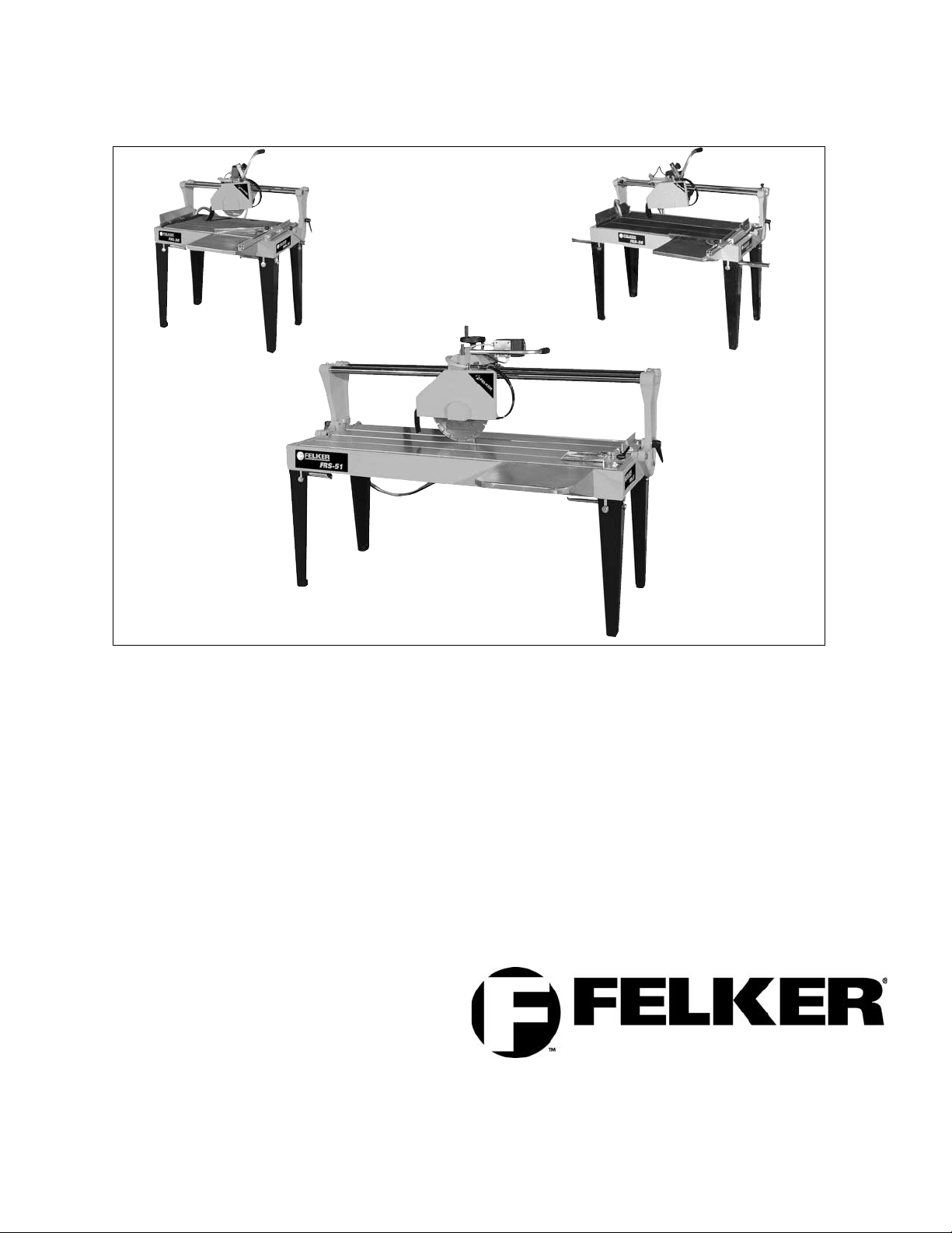
FELKER RAIL SAWS
FRS-30 FRS-38
FRS-51

2
TABLE DES MATIÈRES
1.0 NORMES POUR LA SECURITE ET LA SANTE
1.1 Symboles ........................................................ 4-6
1.2 Autocollants-descriptions et emplacements .......7
1.3 Normes de sécurité:-Faire Ne faire pas .... 26-27
2.0 INTRODUCTION
2.1 Descriptions de la machine ..............................28
2.2 Plaquettes de sécurité sur la machine .............28
2.3 Systèmes de sécurité .......................................28
2.4 Accessoires standard et optionnels..................29
3.0 CARACTERISTIQUES TECHNIQUES
3.1 Données techniques .........................................29
3.2 Niveau sonore ..................................................29
4.0 INSTALLATION
4.1 Levage et transport...........................................30
4.2 Montage et démontage .............................. 30-31
4.3 Branchement électrique ...................................32
5.0 OPERATIONS POUR LA MISE EN EXERCICE
5.1 Déplacement ....................................................32
5.2 Montage du disque et de la roue à profiler -
utilisée seulement sur le FRS 51......................33
5.3 Marche et arrêt .................................................34
5.4 Modalités d’utilisation ................................. 34-35
6.0 ENTRETIEN
6.1 Conseils et instructions pour l’entretien ...........36
6.2 Entretien ordinaire ............................................36
7.0 RECHERCHE DES PANNES
7.1 Inconvénients causes et remèdes ...................37
DIAGRAMMES e pièces de Rechange
FRS-30 and FRS-38.......................................... 38-39
FRS-51.............................................................. 40-41
GARANTIE .............................................................43
CONTENTS
1.0 SYMBOLS, DECALS & SAFETY WARNINGS
1.1 Symbol Definitions ........................................ 4-6
1.2 Decal Descriptions and Locations .....................7
1.3 Safety Warnings: - DOs & DO NOTs ............ 8-9
2.0 INTRODUCTION
2.1 Description of machine ....................................10
2.2 Safety warnings on the machine .....................10
2.3 Safety systems ................................................10
2.4 Standard equipment and option accessories ..11
3.0 TECHNICAL FEATURES
3.1 Technical data..................................................11
3.2 Noise level .......................................................11
4.0 INSTALLATION
4.1 Lifting system and transport ............................12
4.2 Mounting and Disassembling .................... 12-13
4.3 Electrical connection .......................................14
5.0 STARTING UP
5.1 Moving / placing the machine ..........................14
5.2 Installation of Blade or Profile Wheel -
used only on FRS 51 .......................................15
5.3 Start / Stop operations.....................................16
5.4 How to use the machine ............................ 16-17
6.0 MAINTENANCE
6.1 Advice and maintenance warnings..................18
6.2 Typical maintenance ........................................18
7.0 TROUBLE-SHOOTING
7.1 Problems causes and solutions ......................19
DIAGRAMS and SPARE PARTS
FRS-30 and FRS-38.......................................... 20-21
FRS-51.............................................................. 22-23
WARRANTY ...........................................................25

3
CONTENIDO
1.0 NORMAS PARA LA SEGURIDAD Y LA SALUD
1.1 Definición de los simbolos ................................... 4-6
1.2 Descripción de calcamonias y ubicaciones............ 7
1.3 Advertencias de seguridad: Hacer No Hacer . 44-45
2.0 INTRODUCCION
2.1 Descripción de la máquina ................................... 46
2.2 Placas de seguridad en la máquina ..................... 46
2.3 Sistemas de seguridad ......................................... 46
2.4 Accesorios estándar y opcionales ........................ 47
3.0 CARACTERISTICAS TECNICAS
3.1 Datos técnicos ...................................................... 47
3.2 Nivel de ruido........................................................ 47
4.0 INSTALACION
4.1 Elevación y transporte .......................................... 48
4.2 Montaje y desmontaje ..................................... 48-49
4.3 Conexión eléctrica ................................................ 50
5.0 OPERACIONES PARA LA PUESTA EN SERVICIO
5.1 Desplazamiento .................................................... 50
5.2 Montaje del disco y de la rueda perfiladora -
utilizada solamente en FRS 51 ............................ 51
5.3 Arranque y parada ................................................ 52
5.4 Modo de empleo .............................................. 52-53
6.0 MANTENIMIENTO
6.1 Consejos y advertencias para el
mantenimiento ...................................................... 54
6.2 Mantenimiento ordinario ....................................... 54
7.0 LOCALIZACION DESPERFECTOS
7.1 Inconvenientes causas y soluciones ................... 55
DIAGRAME Y PIEZAS DE REPUESTO
FRS-30 and FRS-38 ....................................................... 56-57
FRS-51............................................................................. 58-59
GARANTIA DE LA MAQUINA . ........................................... 61

4
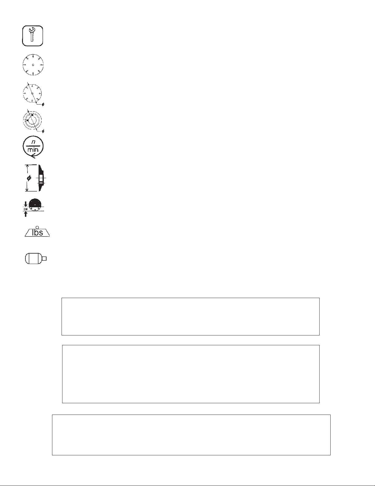
Symbol Defini ions
Symboles
Definición De Los Simbolos
• Please read the instructions for use prior to operating the machine for the first time.
• Avant toute mise en service lire attentivement la notice et se familiariser avec la machine.
• Antes de la puesta en marcha lea detenidamente las instrucciones y familiaricese con la máquina.
• Mandatory
• Obligatoire
• Obligatorio
• Indication
• Indicazione
• Indicación
• Prohibition
• Interdiction
• Prohibición
• Warning Triangle
• Triangle d’advertissement
• Triángwulo De Advertencia
• Wear Eye Protection
• Port obligatoire des lunettes de protection
• Usar Gafas De Protección
• Wear Head Protection
• Port Obligatoire Du Casque Et Des Écouteurs
• Usar Casco De Protección
• Wear Breathing Protection
• Port obligatoire d’un masque respiratoire protecteur
• Usar Máscara De Protección
• The Use Of Ear Protection Is Mandatory
• Port obligatoire da casque antibruit
• Es Obligatorio El Uso De Protección Auditiva
• Wear a Hard Hat
• Port Obligatoire Da Casque Antibruit
• Usar Casco Duro
• Wear Safety Shoes
• Port obligatoire des chaussures de sécurité
• Usar Zapatos De Seguridad
• Wear Appropriate Clothing
• Port obligatoire de la tenue appropriée
• Usar Ropa Adecuada
• Remove The Blade Prior To Hoisting Loading Unloading And Transporting The Machine On Jobsite.
• Démontage Obligatoire Du Disque En Cas D’élingage De Chargement De Déchargement Et DeTransport
Sur Le Chantier.
• Desmontar El Disco Antes De Desplazar Cargar Descargar O Transportar La Máquina En La Obra.

5
• Motor Off
• Arrêt Du Moteur
• Parar El Motor
• Use In Well Ventilated Area
• A Utiliser Dans Un Endroit Bien Ventilé
• Usar En Una Área Bien Ventilada
• Do Not Use In Flammable Areas
• Ne Pas Utiliser Dans Des Ambiances Comportant Un Risque D’incendie
• No Usar In Áreas Inflamables
• Machinery Hazard Keep Hands And Feet Clear.
• Danger! Rester À Distance De La Machine
• Máquina Peligrosa - Mantenga Manos Y Pies Alejados De La Máquina
• No Non-working Personnel In Area
• Zone Interdite Au Personnel Non-Ouvrier
• Prohibido Para Personas Ajenas A La Obra
• No Smoking
• Défense De Fumer
• No Fumar
• Do Not Operate Without All Guards In Place
• Ne Pas Utiliser Avant D’avoir Installé Toutes Les Protections
• No Operar Sin Todas Las Protecciones In Su Sitio
• Always Keep the Blade Guards In Place
• Toujours Vérifier Que Les Protections De Disque Sont Bien En Place
• Mantenga Siempre Las Protecciones De La Hoja En Su Sitio
• Keep Work Area Clean/Well Lit Remove All Safety Hazards
• La Zone De Travail Doit Toujours Être Propre Bien Éclairée Et Ne Présenter Aucun Risque
• Mantenga Limpio El Sitio De Trabajo/Bien Iluminado Elimine Todos Los Riesgos De Seguridad
• Dangerously High Noise Level
• Niveau De Bruit Dangereux
• Nivel De Ruido Elevadamente Peligroso
• Pay Extreme Attention To The Care And Protection Of The Machine Before Starting Up
• Accorder Une Très Grande Attention Á La Sécurité Et À La Préparation De La Machine Avant
De Commencer À Travailler
• Ponga Extrema Atención Al Cuidado Y Preparación De La Máquina Antes De Ponerla En Marcha
• Remove Tools From Area and Machine
• Enlever Les Outils De La Zone De Travail Et De La Machine
• Elimine Las Herramientas Del Área Y De La Máquina
• Electrical Switch - OFF
• Interrupteur électrique-arrêt
• Conmutador De Apagado Eléctrico
• Electrical Switch - ON
• Interrupteur électrique-marche
• Conmutador De Encendido Eléctrico
• Electrical Switch - Start
• Interrupteur électrique-démarrage
• Conmutador De Arranque Eléctrico
6
• Diamond Blade
• Disque diamanté
• Sierra Diamantada
• Blade Diameter
• Diamètre De Disque
• Diámetro De La Hoja
• Pulley Diameter
• Diamètre De Poulie
• Diámetro De La Correa
• Number of Revolutions Per Minute Rotational Speed
• Nombre De Tours/Minutes Vitesse De Rotation
• N° De Revoluciones Por Minuto Velocidad De Rotación
• Blade Flange Diameter
• Diamètre Du Flasque De Disque
• Diámetro De La Brida De La Hoja
• Blade Cutting Depth
• Profondeur De Coupe Du Disque
• Profundidad De Corte De La Hoja
• Machine Mass (lbs)
• Poids De La Machine (en lbs)
• Masa De La Máquina (lbs)
• Electric Motor
• Moteur Électrique
• Motor eléctrico
WARNING
HEARING HAZARD
DURING NORMAL USE OF THIS MACHINE OPERATOR MAY BE EXPOSED TO A NOISE
LEVEL EQUAL OR SUPERIOR TO 85 dB (A)
ATTENTION!!!
RISQUE DE LÉSION POUR L’OUÏE.
DANS DES CONDITIONS NORMALES D’UTILISATION CETTE MACHINE PEUT COM-
PORTER UNE EXPOSITION ACOUSTIQUE D’UN NIVEAU ÉGAL OU SUPÉRIEUR À
85 DB (A) POUR L’OPÉRATEUR PRÉPOSÉ.
ATENCION
RIESGO DE DAÑO AUDITIVO
EN CONDICIONES NORMALES DE UTILIZACIÓN EL OPERADOR DE ESTA MÁQUINA PUEDE
ESTAR EXPUESTO A UN NIVEL DE RUIDO IGUAL O SUPERIOR A 85 dB (A)
• Repairs Are To Be Done By An Authorized Dealer Only
• Les réparations ne peuvent être exécutées que par un distributeur agréé
• Las Reparaciones Deben Ser Efectuadas Únicamente Por Un Distribuidor Autorizado

7
DECAL DESCRIPTIONS & LOCATION
SYMBOLES
DESCRIPCIÓN DE CALCAMONIAS Y UBICACIONES
187043 (1) Decal Locations:
FRS-30 Control Box
FRS-38 Control Box
FRS-51 Cutting Head
193022 (1) Decal Location:
Corner of Blade Guard
193020 (3) FRS-38 Decal Locations:
Both Sides of Water Tank
Operator End of Water Tank
193019 (3) FRS-30 Decal Locations:
Both Sides of Water Tank
Operator End of Water Tank
193021 (3) FRS-51 Decal Locations:
Both Sides of Water Tank
Operator End of Water Tank

8
DO read this entire operator’s manual before operating this machine. Understand all warnings instructions and controls.
DO keep all guards in place and in good condition.
DO wear safety approved hearing eye head and respiratory protection.
DO read and understand all warnings and instructions on the machine.
DO read and understand the symbol definitions contained in this manual.
DO keep all parts of your body away from the blade and all other moving parts.
DO know how to stop the machine quickly in case of emergency.
DO turn the “ON/OFF” switch to the “OFF” position prior to connecting the machine to the power source.
DO inspect the blade flanges and shafts for damage before installing the blade.
DO use the blade flange size shown for each blade size.
DO use only the blade flanges supplied with the saw. Never use damaged or worn blade flanges.
DO use only blades marked with a maximum operating speed greater than the blade shaft speed. Verify speed by checking
blade shaft rpm and pulley diameters and blade flange diameters.
DO verify saw drive configuration by checking blade shaft RPM pulley diameters and blade flange diameter.
DO read all safety materials and instructions that accompany any blade used with this machine.
DO inspect each blade carefully before using it. If there are any signs of damage or unusual wear DO NOT USE THE
BLADE.
DO mount the blade solidly and firmly. Wrench tighten the arbor nut.
DO make sure the blade and flanges are clean and free of dirt and debris before mounting the blade on the saw.
DO use the correct blade for the type of work being done. Check with blade manufacturer if you do not know if blade is
correct.
DO use caution and follow the instructions when loading and unloading the machine.
DO operate this machine only in well ventilated areas.
DO instruct bystanders on where to stand while the machine is in operation.
DO establish a training program for all operators of this machine.
DO clear the work area of unnecessary people. Never allow anyone to stand in front of or behind the blade while the motor
is running.
DO make sure the blade is not contacting anything before starting the motor.
DO use caution when lifting and transporting this machine.
DO always tie down the machine when transporting.
DO use caution and follow instructions when setting up or transporting the machine.
DO have all service performed by competent service personnel.
DO make sure electric powered machines are plugged into a properly grounded circuit.
DO make sure power cords are the proper size and in good condition.
DO maintain a secure grip on the material being cut.
DO clean the water tray frequently.
DO verify the blade arbor hole matches the machine spindle before mounting the blade.
DO clean the machine after each day’s use.
DO follow all electrical codes in your area.
DO consider work area environment. Don’t expose power tools to rain. Don’t use power tools in wet locations.
DO use caution to guard against electric shock. Prevent body contact with grounded surfaces (i.e. pipes radiators ranges
refrigerators).
DO use correct voltage and proper extension cords. Never carry tool by cord or yank it to disconnect it from receptacle. Keep
cord away from heat oil and sharp edges.
DO always carry the machine with the motor stopped.
DO disconnect tools from power source when not in use before servicing and when changing accessories.
DO carefully maintain and clean for better and safer performance. Follow instructions for changing accessories. Inspect tool
cords periodically and if damaged have repaired by authorized service facility.
DO only cut in a straight line.
DO only saw as deep as the job specifications require.
DO always give a copy of this manual to the equipment user. If you need extra copies call TOLL FREE 1-800-365-4003.
SAFETY FIRST!
WARNINGS
DO’s AND DO NOT’s
WARNING: FAILURE TO COMPLY WITH THESE WARNINGS AND OPERATING
INSTRUCTIONS COULD RESULT IN DEATH OR SERIOUS BODILY INJURY.
DO

9
DO NOT operate this machine unless you have read and understood this operator’s manual.
DO NOT operate this machine without the blade guard or other protective guards in place.
DO NOT stand behind or in front of the blade path while the motor is running.
DO NOT leave this machine unattended while the motor is running.
DO NOT operate this machine when you are tired or fatigued.
DO NOT use a wet blade without adequate water supply to the blade.
DO NOT exceed maximum blade speed shown for each blade size. Excessive speed could result in blade breakage.
DO NOT operate the machine if you are uncertain of how to run the machine.
DO NOT use damaged equipment or blades.
DO NOT touch or try to stop a moving blade with your hand.
DO NOT cock jam wedge or twist the blade in a cut.
DO NOT transport a cutting machine with the blade mounted on the machine.
DO NOT use a blade that has been dropped or damaged.
DO NOT use carbide tipped blades.
DO NOT use abrasive blades.
DO NOT use conventional abrasive blades with water.
DO NOT touch a dry cutting diamond blade immediately after use. These blades require several minutes to cool after
each cut.
DO NOT use damaged or worn blade flanges.
DO NOT allow other persons to be near the machine when starting or when the machine is in operation.
DO NOT operate this machine in an enclosed area unless it is properly vented.
DO NOT operate this machine in the vicinity of anything that is flammable. Sparks could cause a fire or an explosion.
DO NOT allow blade exposure from the guard to be more than 180 degrees.
DO NOT operate this machine with the belt guard or blade guard removed.
DO NOT operate this machine unless you are specifically trained to do so.
DO NOT use a blade that has been over heated (Core has a bluish color).
DO NOT jam material into the blade.
DO NOT grind on the side of the blade.
DO NOT lay power cords in or near the water.
DO NOT replace the motor with any motor that does not have a special grounding connection.
DO NOT cut deeper than 1" per pass with a dry blade. Step out to achieve deeper cuts.
DO NOT start cutting with a saw until you have a clear work area and secure footing.
DO NOT operate this machine while using drugs or alcohol.
*****************
This saw was designed for cer ain applica ions only. DO NOT modify his saw or use for any applica ion o her han
for which is i was designed. If you have any ques ions rela ive o i s applica ion, DO NOT use he saw un il you
have wri en Diaman Boar , Inc. and we have advised you.
Diaman Boar , Inc.
17400 Wes 119 h S ree
Ola he, Kansas 66061
In USA 1-800-365-4003
SAFETY FIRST!
WARNINGS
DO’s AND DO NOT’s
WARNING: FAILURE TO COMPLY WITH THESE WARNINGS AND OPERATING
INSTRUCTIONS COULD RESULT IN DEATH OR SERIOUS BODILY INJURY.
DO NOT

10
2.0 INTRODUCTION
2.1 DESCRIPTION OF MACHINE
Thank you for choosing one of our machines.
The manufacturer designs and produces duarble and
reliable machines to solve all cutting processes.
FELKER RAIL SAWS are available in a range of mod-
els to cut material upto 51” in . They can be placed in-
side factories or used directly on building yards.
These rail saws are designed to use diamond blades to
cut marble or granite pieces with dimension size and
weight allowed by machines’ structure.
Location and name of principal components (Fig.1)
1) Blade Guard
2) Guide Bars
3) Control Switch Box
4) Water Tank
5) Water Pump
6) Handwheel to adjust cutting depth - FRS-51
7) Table Legs
8) Tilting Bridge 0°- 45°
2.2 SECURITY WARNINGS ON THE MACHINE
The decals on the machine must always be kept clean
and in a readable condition.
The safety warning decals are fixed on the blade guard
as shown on page 7.
2.3 SAFETY SYSTEMS
-Blade Guard: a protection device that avoids acci-
dental contacts with the blade.
It is obligatory to have this device securely mounted
before the machine is turned on.
-Overload pro ec ion: the overload protection stops
the motor in case of overload. Wait a few minutes
before turning the motor on again.
-Con rol Swi ch: easy access to the Start- Stop but-
tons. In case of interruption of electrical power saw
will remains OFF until Start button is again engaged.
This prevents the saw from turning on accidentally
when electrical power is restored.
Fig. 1
1
23
4
5
6
7
8

11
MODEL FRS 30 FRS 38 FRS 51
Power - HP 1.5 1.5 2
Supply voltage - Vac 115 115 230
Supply frequency - Hz 60 60 60
Phase 1 1 1
Full load amps - A 14.4 14.4 8.3
Blade motor - rpm 3400 3400 1700
Blade capacity - in. (mm) 10 (250) 10 (250) 14 (350)
Arbor size - in. (mm) 5/8 (15.9) 5/8 (15.9) 1 (25.4)
Length of Cut - in. (mm) 30 (750) 38 (950) 51 (130)
Depth of Cut at 90° - in. (mm) 2.6 (65) 2.6 (65) 4.1 (105)
Depth of Cut at 45° - in. (mm) 1.2 (30) 1.2 (30) 2.4 (60)
Cutting table 36.5 x 17.3 44.5 x 17.3 60 x 22.5
L x W - in. (mm) (930 x 440) (1130 x 440) (1520x 570)
Side extension 12.1 x 11 12.1 x 11 15.7 x 13.8
L x W - in. (mm) (310 x 280) (310 x 280) (400 x 350)
Saw dimension w/Leg & extension 48.4 x 30.7 x 47.2 56.3 x 30.7 x 47.2 66.9 x 39.4 x 50.8
L x W x H - in. (mm) (1230x780x1200) (1380x780x1200) (1750x1000x1290)
Saw Weight uncrated - lb (kg) 145.5 (66) 154.3 ( 70) 317.2 (144)
Crated weight - lb (kg) 170 (77) 181 (82) 350.5 (159)
3.0 TECHNICAL FEATURES
3.1 TECHNICAL DATA
2.4 STANDARD EQUIPMENT AND
OPTION ACCESSORIES
S andard Equipmen :
• Open End 30mm Wrench to change the blade
• Rip Fence
• Side Extension Table
Documen equipmen :
• Instruction manual
3.2 NOISE LEVEL
Noise produced from the machine on its own is less
than 70dB (A).
General noise level could INCREASE when:
• multiple saws are in the surroundings
• saw is inside of a building
• materials are being cut; some material types produce
more noise than others
• with use of improper acoustic safety devices.
Noise level could DECREASE by:
• reducing the speed rate of cut
• always using blades that are in good condition
• using silent core or StealthTM Blades.
NOTE:
Acoustic pressure over 85 dB (A) could be dangerous
for your hearing health it is recommended to always
use an approved hearing safety device while operating
the saw.
12
4.0 INSTALLATION
4.1 LIFTING SYSTEM AND TRANSPORT
Unpack he machine and check ha no par s
are missing or damaged. In case par s are
damaged during shipping, immedia ely con-
ac he carrier and manufac urer.
• Check ha lif ing device used is adequa e o carry
he weigh of he machine. See char in 3.1
Techinical Da a.
• Avoid lif ing he machine over persons or hings
ha could ge seriously hur or damaged in case
of i em falling.
• Before any lif ing opera ions always announce i
o hose around.
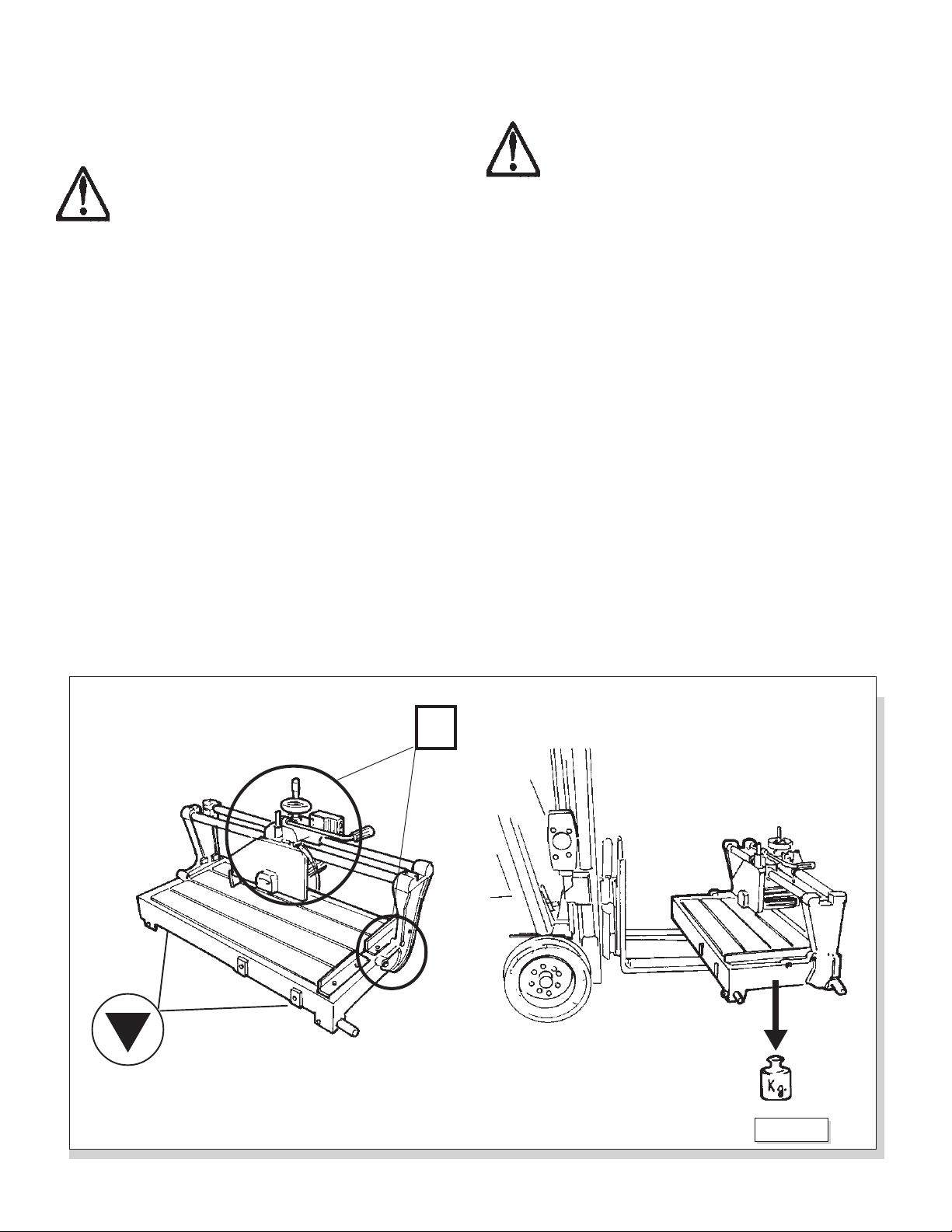
• Before lif ing he machine, always be sure ha
head is blocked in he cen er of he Guide Bars
using he Limi Rings, I (Ref. 4.2, Fig. 4).
To reduce volume and make transport/lifting operations
easier dismount all four legs.
The machine is packed inside a carton box.
The machine is to be lifted by a forklift placing it as
shown on Fig. 2.
4.2 MOUNTING AND DISASSEMBLING
All moun ing and disassembling opera ions
mus be done wi h machine “OFF” and un-
plugged.
• Proceed wi h moun ing and disassembling opera-
ions very carefully wearing safe y gloves and
proper foo wear.
• Before placing the machine on the floor keep it on
the forklift and screw on the legs with its
proper key A+B (Fig. 3).
• Lower the arms of the forklift and set the machine
carefully on the floor.
• Install the side table extension C (Fig. 3) and tighten
the knobs D (Fig. 3).
• Mount the fence on side part F+E (Fig. 3) and hold it
with proper Lever Knob G (Fig. 3).
Fig. 2
Locked
Lift points

13
• Unblock the head by loosening the knobs I (Fig. 4)
and sliding the two limit rings L (Fig. 4) to the end of
the Guide bars.
• Replace the screws M (Fig. 5) of the tilting bridge N
(Fig. 5) with the M10 lever knobs O (Fig. 5) supplied
loose with the machine.
Fig. 4
L
L
II
Fig. 3
A
B
B
E
D
F
G
Fig. 5
ON
M
C
14
4.3 ELECTRICAL CONNECTION
• ONLY a qualified elec rician should con-
nec he machine o he fac ory elec ric
power supply per local elec rical codes.
• All ground wires mus be properly con-
nec ed.
• Machine MUST be connec ed o elec rical
supply of he same power as he require-
men s indica ed on mo or ID pla e or see 3.1
Technical Da a.
The machine is equipped with a 3 meter long Power
Cord and Plug.
In case the machine is placed inside a factory install a
properly sized magnetic circuit breaker and protect for
the wiring as required by local codes.
When the the machine is used on temporary job sights
connect the machine to power source outlets with the
plug installed on the machine respecting local safety
regulations.
5.0 STARTING UP
5.1 MOVING – PLACING THE MACHINE
• Before moving he machine, disconnec i
from he elec rical power supply.
• Always use cau ion when moving he ma-
chine o preven damage or personal injury.
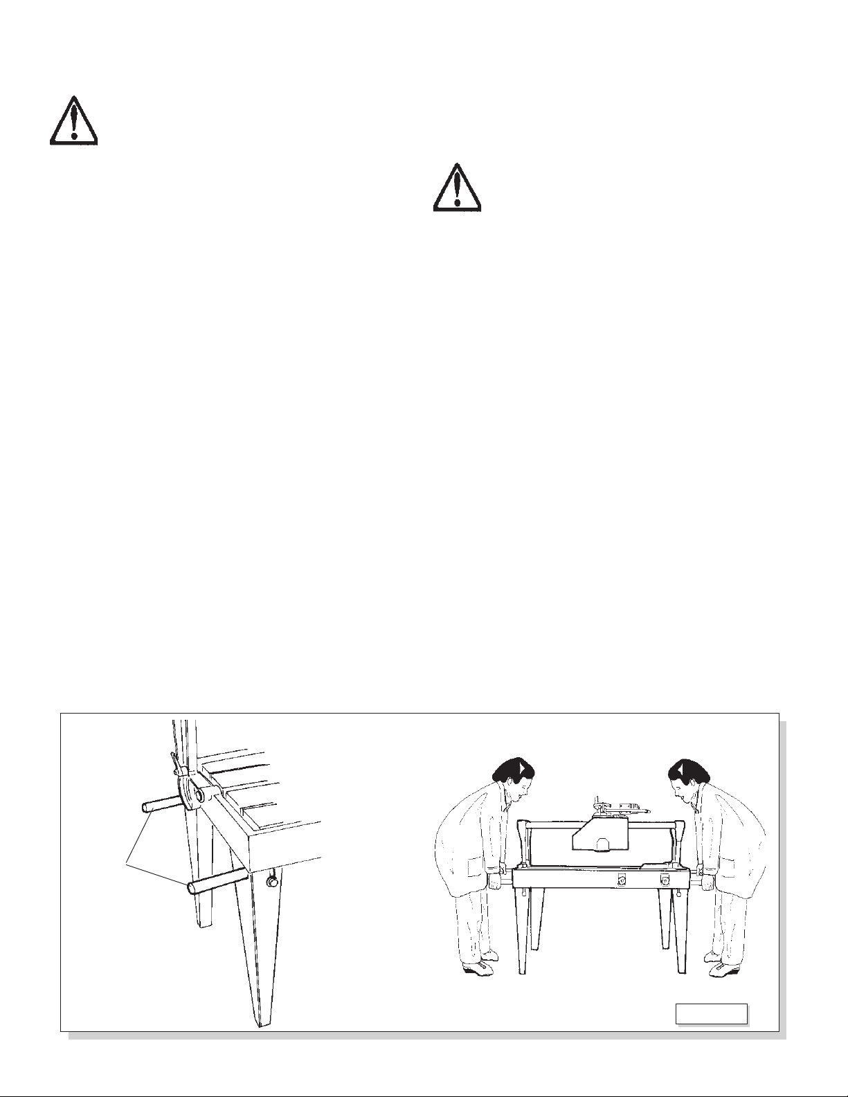
Before moving the machine manually:
- Slide the head to the center of Guide Bars so the
weight is balanced
- Secure the head by tightening the knobs of the 2
limit rings
- Make sure that lever knobs locking the tilting bridge
of the machine are tight.
- Empty the water tank.
- Pull out the lift handles A (Fig. 6) from under the
table and carefully lift to a minimum height to move
the machine.
Two or four men can move the machine (Fig. 6) (de-
pending on the weight).
Fig. 6
A

15
Fig. 7
A
B
C
DE
F
5.2 INSTALLATION OF THE BLADE
OR PROFILE WHEEL- USED ONLY ON FRS 51
• ALWAYS urn off he machine and discon-
nec he power source before ins alling or
replacing he blade.
• ONLY use correc size ools for ins alling
Blade.
• ONLY use good quali y diamond blades
according o machines fea ures and for he
ma erial o be cu .
• Always use he required blade diame er
because i affec s he maximum cu ing
dep h and he useful cu ing leng h.
• Be sure he diamond blade is correc ly
balanced and ensioned and is properly
igh ened on arbor.
• Avoid cu ing pieces of ma erial ha are
oo big, oo small, or difficul o se prop-
erly on working able.
• The blade life depends on its daily use type and thick-
ness of piece to cut and proper water flow to keep it
cool.
• The blade should be replaced whenever the cutting
quality is not optimal because it could be worn out or
deformed. Operating with a worn out or defective
blade could be dangerous.
• Replace the blade or install the profile wheel by stand-
ing in front of the machine as follows.
1. Tilt the blade 45° and loosen the 2 screws A (Fig. 7)
behind the blade guard with a 10mm wrench and re-
move the guard B (Fig. 7).
2. Hold the motor spindle C (Fig. 7) and unscrew the blade
shaft nut (CW) clockwise using the 30mm wrench D
(Fig. 7) supplied (only on FRS 51). For the FS-30 &
38 hold the motor shaft from turning with a 6mm hex
key inserted into the back side of the motor and loosen
the nut (CW) with a 19mm wrench.
3. Once the blade is removed check the outer flange E
(Fig. 7) and inner flange interior surfaces and if needed
replace or clean them to remove any debris that might
prevent the blade from properly seating inside the
flanges.
No e: When using the thick-cored profile wheel on the
FRS 51 do not use the outer flange E (Fig. 7).
4. Mount the new blade in the direction of the rotation
arrow marked on the blade F (Fig. 7). It must be the
same direction as the arrow on the blade guard. (clock-
wise from the front).
5. After installing the new blade or profile wheel be sure
to securely tighten the nut counter-clockwise with the
correct wrench while holding the motor spindle.
6. Before using he machine be sure he blade guard
is securely in place. Re-install the blade guard B (Fig.
7) and securely tighten the 2 screws A (Fig. 7) using an
M10 wrench.

16
5.3 START / STOP OPERATIONS
Your machine is equipped with an electrical control box
complete with a magnetic ON-OFF switch composed
of 2 buttons with the following functions (Fig. 8):
(A) RED button: STOP
(B) GREEN button: START
NOTE:
If the electrical power is interrupted the machine will
remain “OFF” when power is restored until operator
again pushes the START button.
5.4 HOW TO USE THE MACHINE
• Before s ar ing he machine, be sure ha
blade and blade guard are securely igh -
ened.
• Se he machine where no hing danger-
ous is around i ha can in erfer wi h cu -
ing opera ions.
• Connect the machine to a properly protected and
grounded power outlet.
• Before starting the machine install the drain plug into
the hole located in the bottom ot he water tank. Fill
the tank with clean water until it fully covers the water
pump. Also flush tank and hoses with clean water to
remove debris after cutting each day.
• Place the material to cut against the fence and in line
with cutting plane of the blade.
• Lower/raise the handwheel C (Fig. 9) to adjust cut-
ting height (FRS-51 only).
• Never place hands along cu ing line of blade
opera ion.
• To turn on the blade motor and water pump push
the “green” start button D (Fig. 9). Both the blade
motor and water pump will start.
• Before s ar ing he cu ing opera ions, check for
adequa e wa er flow o he blade. Make adjus men
o flow valve E (Fig. 9) as needed.
The pump MUST ALWAYS work wi h sufficien wa er
in he ank (Pump should be fully submerged.) Wa er
is used o cool he pump and he cu ing blade.
Wi hou wa er, bo h could fail and be permanen ly
damaged.
• Pull handle F (Fig. 9) carefully to advance the cutting
blade to and through the material.
Fig. 9
CD
F
E
Fig. 8
B
A
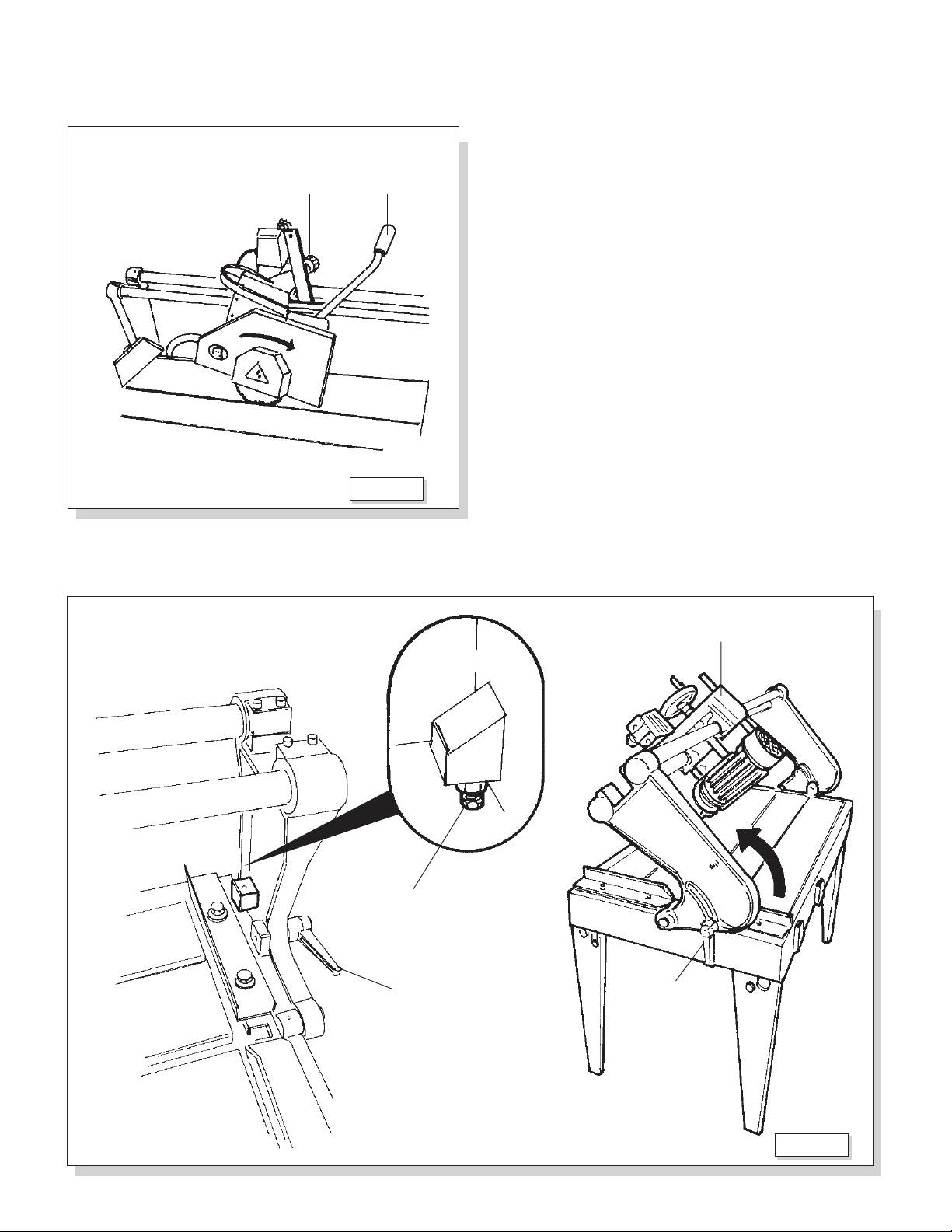
17
• On Models FRS-30 and FRS-38 you must pull the
handle G (Fig. 10) downwards to set depth of cut and
lock in position by tightening Knob H (Fig. 10).
• Carefully pull handle F (Fig. 10) & G (Fig. 10) to ad-
vance the cutting blade through the material.
• Make the cuts from left to right with the material with
the material up against the backstop on the far right
of the table.
• To tilt the head J (Fig.11) 0°- 45° loosen the two
side lever handles K (Fig. 11). Adjust to the angle
needed and tighten the lever handles again.
NOTE:
To accurately set 0° tilt adjust the micrometric screws
L (Fig. 11).
Fig.10
G
H
Fig.11
J
K
L
K

18
6.0 MAINTENANCE
6.1 ADVICE AND MAINTENANCE WARNINGS
• Before any service on he machine AL-
WAYS disconnec i from he elec rical
source.
• Never use flammable produc s o clean
he machine.
• All services no described in his manual
mus be effec ed ONLY by qualified person-
nel.
• ALWAYS use proper safe y equipmen .
6.2 TYPICAL MAINTENANCE
DAILY:
• To keep the machine in good conditions clean follow-
ing:
- floor surrounding
- machines’ components
- water tank
- water pump E (Fig. 12) inlet.
• Grease sliding guides at grease fittings A (Fig. 12)
using a manual grease gun B (Fig. 12)
Recommended Grease: General purpose #2 Lithum
based grease without molybedenum disulfide.
EVERY 2 WEEKS:
• Put grease on the vertical screw C (Fig. 12) using a
small brush D (Fig. 12)
Recommended Grease: General purpose #2 Lithum
based grease without molybedenum disulfide.
Fig.12
C
B
A
ED

19
7.0 TROUBLE-SHOOTING
7.1 PROBLEMS, CAUSES AND SOLUTIONS
After pushing the START button the
machine remains off.
The saw motor doesn’t rotate.
The saw motor loses power or stalls
while cutting.
The blade motor works but insufficient
or no water flows over the blade.
Material cut is chipped when finished
cutting.
A)No electricity.
B)Electric wire or switch damaged
C)Fuses on electric line are burnt
D)Machine not connected to correct
voltage required.
A)Wrong voltage
B) Bad Motor capacitor.
A)Cutting feed rate is too fast
B)Blade is dull or worn out.
C)Voltage is too low.
A)Water hoses and connections are
dirty.
B)Water hose has kink.
C)Insufficient water level for the
pump.
D)Filter of water pump is dirty
A)Diamond blade out of tension bent
or using incorrect blade for the ma-
terial.
B)Feed rate too fast at end of cut.
C)Blade not fully penetrating through
the material.
A)Check: electrical connections cir-
cuit protection device magnetic
switch inside control box.
B)Repair or replace by qualifiied
electricain
C)Check fuses inside electric box
D)Require assistance.
A)Check electrical connection.
B)Replace by qualified electrician.
A)Reduce cutting speed.
B)Open blade to expose diamonds
or replace blade.
C)Extension cord may be too long.
Or have electric power checked by
qualified electrician.
A)Flush hoses and connection parts
with clear water to clean
B)Straighten or replace hose.
C)Add water to correct level.
D)Clean filter of water pump
A)Replace with new correct blade
B)Slow the feed rate near end of cut.
C)Increase depth of cut. Blade
should extend about 1/4” beneath
table surface.
PROBLEMS CAUSES SOLUTIONS
20
1 193737 1 ead Adj. ousing
2 193735 1 Spring
3 193740 1 Pivot Bracket
4 193697 1 Bearing Mtg Plate
5 193698 2 Bearing ousing
6 193689 1 Clevis Pin, 6x30
7 193690 1 Clevis Pin, 6x40
8 193693 2 Pivot Stud
9 193738 1 Cap Plug
10 193739 1 ead Adj. Rod
11 193732 4 Washer, Plastic
12 193723 1 Motor Plate
13 193662 1 andle Grip
14 193657 1 Knob, M8x25
15 193653 1 Kit, Linear Bearing (Set/4)
16 193663 1 Kit, Oil Seal (Set/4)
17 193699 1 Blade Guard, 10”
18 193672 1 Blade Flange - Inner
19 193678 1 “Y” Tube Fitting
20 193677 1 Water Valve
21 193679 1 ose Barb Fitting
22 193682 1 Water Tubing, Braided 20x16
23 193651 1 Splash Flap
24 193665 2 Limit Ring
25 193655 2 Knob, Limit Ring M6F
26 193669 1 Motor Assy: 1.5 P 115V-60 z
-- 193797 1 Capacitor, Motor: 110 mFd/400Vac
27 193741 1 Switch Control Assy
28 193713 2 Shoulder (Left & Right)
29 193714 2 Stop Block, Adj,
30 193660 2 Knob, Lever M10x35
31 193661 2 Knob, Lever M8x20
32 193692 2 Pivot, Shoulder
33 193683 1 Fence, Sq. Rail
DIAG PART QTY DIAG PART QTY
LOC NO REQ DESCRIPTION LOC NO REQ DESCRIPTION
34 193717 1 Angle Guide
35 193656 1 Knob, M6x20
36 193688 1 Screw - Special
37 193695 1 Nut, Square M6
38 193733 1 Scale, Dual
39 193736 1 Nut, Square
40 193696 1 Mounting Bar
41 193716 1 Backstop Angle
42 193734 1 Splash Shield
43 193707 1 Side Table Extension
44 193659 2 Knob, Lever M8x30
45 193676 1 Water Pump 115V-60 z
46 193680 1 Set, Table Legs
46a 193702 2 Table Leg, Left
46b 193747 2 Table Leg, Right
47 193681 4 Table Leg Pad
48 193727 4 Table Lift andle
49 193667 1 Drain Plug
50 178048 1 Wrench, 19mm Open-end
51 193674 1 ex Key, 6mm
52 193703 1 Water Tank - FRS-30
-- 193704 1 Water Tank - FRS-38
53 193710 2 Table Slat, Front - FRS-30
-- 193711 2 Table Slat, Front - FRS-38
54 193708 1 Table Slat, Rear - FRS-30
-- 193709 1 Table Slat, Rear - FRS-38
55 193686 1 Set, Guide Bars - FRS-30
-- 193687 1 Set, Guide Bars - FRS-38
56 193673 1 Blade Flange, Outer
57 193745 1 ex Nut, 12mm L. .
58 193743 2 Water Tube, Black 10x6,5x380
59 193744 1 Wrench, 10mm Open-end
60 185233 1 ex Key, 5mm
NS 030129 1 Plug, 5-15P 125V-15A
SPART PARTS LIST for FRS-30 & FRS-38
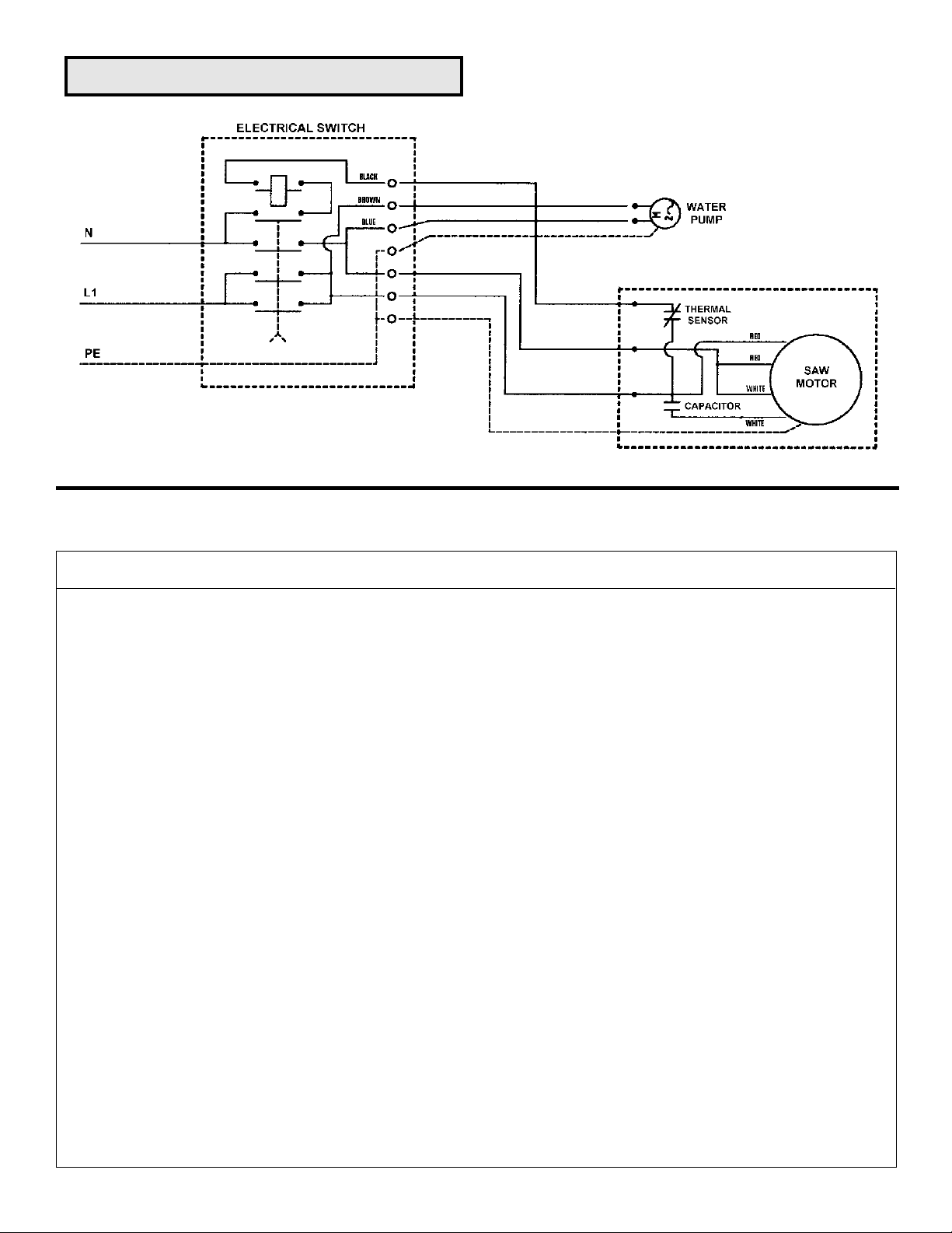
ELECTRICAL DIAGRAM: FRS 30 & 38
This manual suits for next models
5
Table of contents
Languages:
Other Felker Saw manuals

Felker
Felker tr-850 Use and care manual

Felker
Felker Super Tile Master STM-1000 Use and care manual

Felker
Felker PaverMatePM-15HT User manual

Felker
Felker Mason Mate II Use and care manual

Felker
Felker TKM-123 Use and care manual

Felker
Felker TM-1HT User manual

Felker
Felker TM-75 User manual

Felker
Felker TM-75 Use and care manual

Felker
Felker TILE MAGIC TMG-851 Use and care manual

Felker
Felker FTS-150 Use and care manual


