Bridgeport Series 2 User manual

J
I
,l
,
;. 1
;t
te
PART NO.0596351
{
o

Ba-.'TrFt€*
tq-v-?+
I 8 tz-sS
L- 6'9<
q

MPOR NT tr l/r'.,6<\z1c
SAFETY NOTICE - BRIDGEPORT SER!ES I! INTERACT 2
PERFORM ALL ACTIONS IN THE MANNER STATED IN THIS MANUAL.
NEVER OPERATE THE MACHINE WITHOUT PROPER CUTTER GUARDING.
ENSURE YOU KNOW HOW TO STOP YOUR MACHINE.
DO NOT TAMPER WITH THE MACHINE
KEEP MACHINE AND SURROUNDING AREA CLEAN AND TIDY.
GUARDING
a
The guard supplied as standard equipment with the Bridgeport Series ll lnteract 2 (pictured above) is made of a clear
material (Lexan or equivalent) having high impact resistance to provide operator safety and a clear unobstructed view of
the component and cutter. A door at the front allows easy access for tool changing or loading of components. This guard
lS NOT SUITABLE FOR ALL OPERATIONS of which the machine is capable, and great care should be taken to ensure
the guard you use is safe for the operation being performed.
I

Attention is drawn to the requirements of the
Health and Safety at Work Act 1974 which applies
to the U K. Similarly in other countries the machine
should always be operated to conform with the
appropriate regu lations.
is
rI.
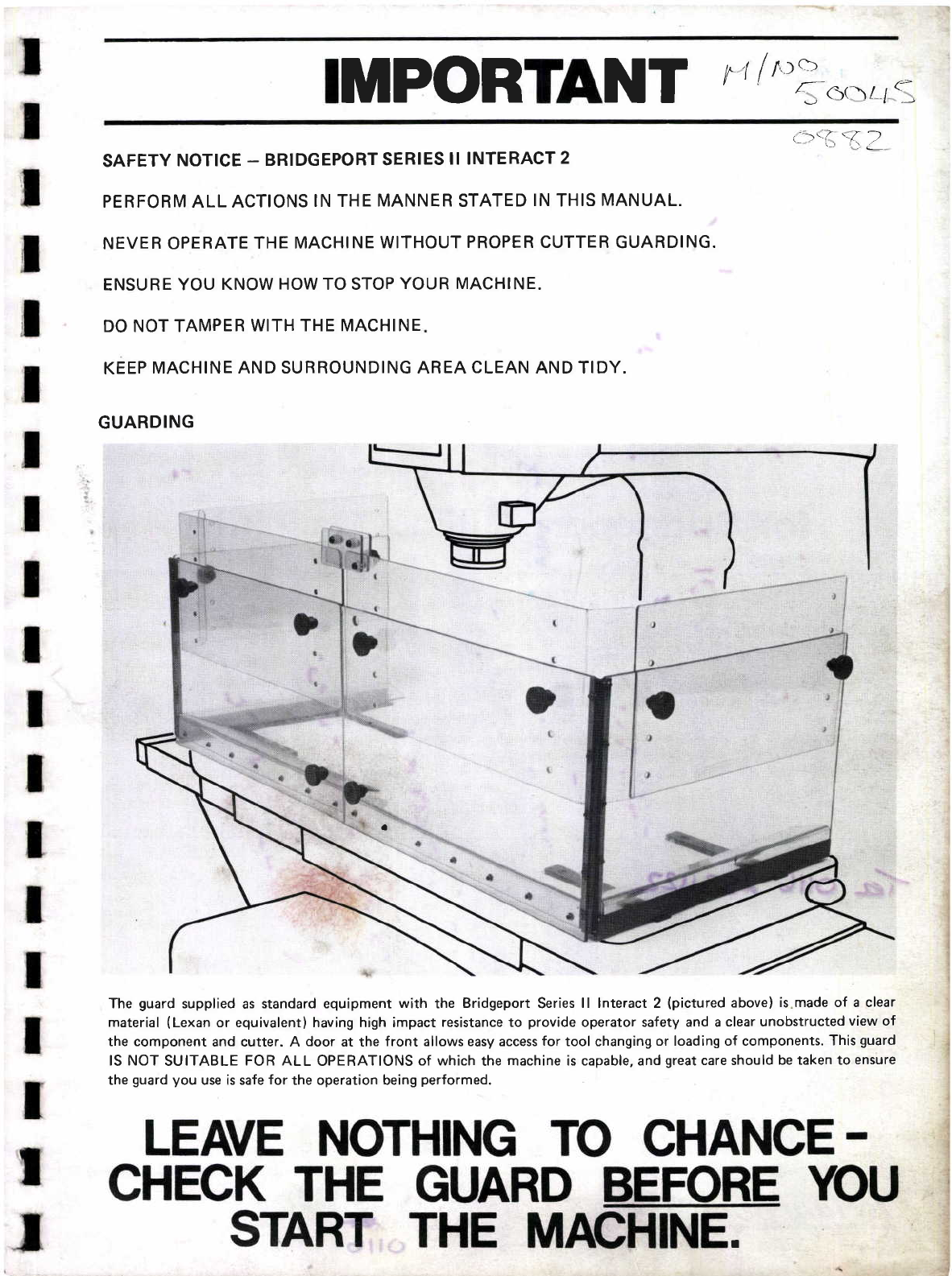
All machines in the Bridgeport range, together with their accessories are designed and produced to ensure safety to the
operator as far as is reasonably practicable.
Every machine and where appropriate, the attachments, are
provided with a cutter guard which will satisfy statutory
requirements for a large number of applications. However,
as the machine and attachments are designed for general
engineering applications the guard supplied will not cover
every possible requirement for effective guarding of the
cutter. Under no circumstances should any machine from
the Bridgeport range of machines be used without the
correct safety guard for the operation to be performed. As
we have no control over the end use of our machines, it is
the user's responsibility to ensure that the machine is
properly used and guarded for every operation.
i
t
i
I
i
I
i
I
I
i
(.- otlt 253t(22-.
, Bridgeport Machines Division of Textron Limited,
P.O. Box 22, Forest Road,
Leicester LE5 0FJ, England
Telephone: ( 531122; Telex: 34598
ollb

PART NO. 0596351
INSTALLATION & MAINTENANCE
MANUAL
FOR THE
SERIES II INTERACT 2
MILLING, DRILLING & BORING MACHINE
,l
I
This manual provides information which is proprietary to Bridgeport Machines
and its suppliers and is made available for the use and maintenance of our
products. Any use, reproduction or disemination of this information for any
other purpose wittrout written permission is prohibited.
The information in this document is subject to change without notice and does
not constihrte a commitment by Bridgeport Textron.
October 1982

Section
II
III
IV
VII
1.1
7.2
LIST OF CONTENTS
MACHINE INSTALLATION
Preparation of the Machine Location
Electricd Service
PREPARATION FOR OPERATION
2.7 Cleaning the Machine
2.2 Lubrication
MACHINE COMMISSIONING
3.1 General
3.2 CommissioningProcedure
MACHINE MAINTENANCE - THEORY OF OPERATION
4.7 The XY Servo Motor Drive
+.2 Knee Drive
+.3 Lubricating System
4.+ TheZ Axis Drive
4.5 The Milling, Drilling and Boring Head
4.6 Specification
POWER DISTRIBUTION
5.1 Power Disuibution
CONTROL AND AXIS DRIVES
Axis Drive Unit System Description
Replacement of Axis Drive Unit
Conuol System Description
Fitting a New Controller
Sofrware Limits
Controller Buffer Battery Replacement
Page
7-2
7-2
7-2
2-l
2-l
2-7
3-1
3-1
3-7
4-1
4-r
4-r
+l
4-2
+-3
+-4
5-1
5-1
6-7
6-7
6-7
6-3
6-3
64
6-5
7-7
7-7
7-3
7-8
7-9
7-12
7-1+
7-17
7-20
7-22
V
VI
6.1
6.2
6.3
6.4
6.5
6.6
BASE ASSEMBLY AND MAINTENANCE
7.1 Drive Belt Replacement
7.2 XtA V Axis Diive Motor Replacement
7.3
7.4
7.5
7.6
7.7
7.8
7.9
Table and Saddle Removal
X&YAxisBallscrew
Air Assist Pedestal
Limit Switch Replacement
Lubrication
X&YAxisGibs
Lost Motion & Backlash Compensation
BT/%M/10A2

Section
vm
Ix
x
XI
Page
8-1
8-1
8-1
8-8
8-15
8-16
8-17
9-1
9-1
9-2
10-1
LIST OF CONTENTS (Cont'd)
SERIES II INTERACT 2 HEAD ADJUSTMENT
AND MAINTENANCE
8.1 Lubrication
8.2 Power Transmission
8.3 Quill and Spindle
8.4 Quill Limit Switches
8.5 Alignment of Quill Housing Assembly to Drive Motor
Housing Assembly
8.6 Bdl Quill Extension Inspection
SPARE PARTS LIST
9.1 Electrical Parts List
9.2 Mechanical Parts List
PREVENTIVE MAINTENAI{CE
FAULT FINDING
10.1 Warranty
lO.2 Singte Shift Operation and Using Coolant on all Operations
10.3 Multiple Shift Operations and Punitive Environments
10.4 MaintenanceSummary
10-1
1Gl
1G2
104
1 1-1
{p
t.
f.

lrigure
I,IS'I' O F' I LLUS'I'RA'TIONS
Series II lnteract 2 Milling Machine
Machine Base Layout
lnstallation Plan View
Lubrication System
Axis l)rive Unit Connections & Adjustments
Rear of Conrrol System Showing Connections
System Wiring Diagrrm
'l'able and Saddle Arrangemcnt
Knee Arrangement (2 sheets)
I)ual l)ial La1'out
Elevating Screlv Assembly
Limir Srvitch & 1'rip Dog Arrangement
fuyout of Services
Knee Lubrication System
Saddle to'l'able Gib Setting
Saddle to Knee Gib Setting
Milling Head Assembly
Special -l'ool 5'l'6921 Head Lift Bracket
Z Axis Assembly
Spindlc Brake antl Back Cear Assembly
Quick Change Locknut Assembly
Quill Limit Srvitch Setting
llall Quill Extension 'l'orque on Nut Set-up
Ball Quill & Nur l"lushing
Ball Quill Extension t;lushing
Page
-1
-3
-4
2-7
l-l
t-2
l-3
7-l
7-2
I
I
I
2-l
6-l
6-2
6-'
6-2
6-6
6-7
7-4
7-5 to
7-6
7-7
7-13
7-18
7-19
7-20
7 -22
7-22
8-3
84
8-7
8-11
8-13
8-14
6-re
8-19
8-20
7-3
74
7-5
74
7-7
7-8
7-9
8-l
8-2
8-3
84
8-5
86
8-7
8-8
8-9

LEVELS OF MAINTENANCE
Level 1 (Operator) Maintenance
The machine operator (or other customer representative) is not assumed to have any detailed
knowledge of the equipment. He is not assumed to have any (electrical) tools for maintenance.
Level 1 maintenance consists of keeping the equipment clean, lubricating (and ensuring that
lubricant reservoirs are full), making sure that power is turned on, and that proper start-up and
operating procedures are being followed.
Lwel 1 personnel are not auttrorised to make adjustment or replace comPonents.
Level2 Maintenance
The level 2 service man is assumed to have a fair knowledge of ttre equipment.
He is assumed to have a VOM, spare fuses, printed circuit boards etc.
Level2 maintenance consists of all level 1 procedures plus adjustment of power supply voltages
and replacement of major sub-assemblies, such as seryo motors, cables, drive boards, fuses etc.,
plus certain individual components such as contactors, power switches and relays.
Level2 personnel are not recommended to replace individual components other than those
enumerated above.
Level 3 Maintenance (Bridgeport Field Service or Specially Trained Dealer Service)
For all level 3 maintenance such as replacement of individual electronics p,rts etc., it is strongly
recommended that this be carried out only by Bridgeport Field Service Engineers, or their
Trained Deder Service Staff.

Figure 1-1 Series II Interact 2 Milling Machine
1-1

SECTION I
MACHINE INSTALLATION
1.1 PREPARATION OF THE MACHINE LOCATION
1.1.1 Foundation and Clearances
When setting the machine on a prepared foundation of concrete (optional) or on the shop floor,
use shim plates, adjustable mounting pads or thin grouting to compensate for unevenness in the
floor.
Figure 1-2 shows the base dimensions and the 17 mm (27132") diameter clearance holes for
16 mm (S/a':;.6o1,s, should it be required to bolt the machine to t}re floor.
Figure 1-3 shows the necessary clearances around the machine for access door opening for
maintenance and to continue the remainder of the installation.
1.2 ELECTRICAL SERVICE
1.2.7 Referencelnformation
The machine is wired f.or 27O,22O,2+O,380 v or 4OO, 42O,44O, 460,480 v and all fused 20
amps. Check the label on the outside of the Power Equipment Enclosure on the side of the
machine to determine the exact figures for your installation.
The electrical service entry is at the rear of the Power Equipment Enclosure (see Figure 1-3)
where a 20 mm diameter hole has been provided for electrical conduit fittings.
WARNING: DO NOT CONNECT ELECTRICAL SUPPLY AT THIS STAGE
7-2

(4) LEVELLING
BOSSES ON BASE
108 mm
(4ll+")
1180 mm
(46 712"\ 965 mm
(39")
LEVEL POSITION
CROSS AND LENGTH WISE
FOR 16 mm (5/8") BOLTS
660 mm
(26")
787 mm
(31")
Figure 1-2 Machine Base Layout
t-3
-

20 mm DIA HOLE FOR
314" DIA CONDUIT FITTING
508 mm
(20")
1638 mm
(64Y2"')
559 mm' 279 mm
(22") (11")+
1194 mm
(47")
691 mm
(27Y2")
1346 mm
(53")
Figure 1-3 Installation Plan View
74
-
II

SECTION II
PREPARATION FOR OPERATION
2.7 CLEANING THE MACHINE
After final acceptance testing at the factory, nvo major operations are carried out which must
be fully understood in order to do an effective job of cleaning the machine:
1. Masking and Spray Painting.
2. Cosmolene rust preventative application with a Spray Gun.
Clean all rust preventative from the machine with kerosene .
WARNING: DO NOT USE GASOLINE, CHLORINATED HYDROCARBONS OR ANY
OTHER INFLAM]VIABLE OR TOXIC CLEANING AGENT.
Clean and lubricate all exposed sections of the table, saddle and knee ways. This includes the
underside of all ways. It also includes the possible necessity to scrape paint from some of the
hidden surfaces where the masking may not have been completely effective.
2,2 LUBRICATION
There are two classes of lubrication systems:
1. Those areas lubricated for life such as spindle bearings, transmission gearbox etc.
2. The forced lubrication system from the automatic one-shot pump to supply ways, gibs and
ballscrews including the Z axis (see Figure 2-1).
Figure 2-1 Lubrication System
2-7

SECTION III
MACHINE COMMISSIONING
3.7 GENERAL
Initial machine commissioning MUST be carried out by Bridgeport Field Service or their trained
Dealer Service.
Electrical power must not be applied to the machine until requested by the Engineer carrying
out the commissioning.
3.2 COMMISSIONINGPROCEDURE
3.2.1 PreliminaryInspection
The following checks are to be carried out before the machine main isolator is switched on
3 .2.1.7 Visual Inspection
a. Check the machine for any transit damage and check that all hardware fixings are secure.
b. Check that all fuses are installed and are secure .
c. Check that the lubrication reservoir has been filled with the correcr grade of oil and operate
the plunger to check that the system is pumping the lubricant.
3.2.7.2 Wire Checks
a. Check that ALL terminal strip screws in the power cabinet are secure.
b. Check that the D.C. feed motor connections are secure.
c. Check that the connections to the head limit switches are secure.
3.2.2 Mains Su Checks
a. Measure the incoming 3 phase supply on the supply side of the main isolator and record rhese
readings below:
Lines L1 to L2 ....... volts A.C.
ii. Lines Ll to L3 ....... ......... volts A.C.
iii. Lines L2 to L3 ....... ......... volts A.C.
b. Check with the customer for any known, regular variations of supply voltage which are
widely different from the nominal values measured in (a) above.
3-1

c. Check that transformers T7,T2 (located in the power cabinet) and the spindle motor are
wired for the correct supply voltage and record this below:
T 1 wire numbers 1 06 and 7O7 , T2 wire numbers 1 1 1 md 172
Equipment wired for volts A.C. oPeration
d. Check that the spindle motor overload O/L is correct for the operating voltage selected.
3.2.3 ElectricalChecks
Switch the main isolator ON and carry out the following electrical tests:
a. Measure the A.C. voltage between wire numbers 8 and 9, and check that it falls within the
range 110 volt A.C. +. 5 volt.
Voltage reads ........ volts A.C.
b. Measure the D.C. voltage between wire numbers 116 and 90 and check that it falls within the
range 24 volts D.C. to 28 volts D.C.
Voltage reads ........ volts D.C.
c. Measure the smoothed D.C. voltage terminals 65 and 90 and check that it falls within the
range 22 volts D.C. to 26 volts D.C.
Voltage reads . volts D.C.
3.2.4 Pneumatics
Set the respective pressure regulators to provide a nominal pressure of 80 psi (5.62 kglcm2) to
a. The spindle brake and speed change pneumatics.
b. The air assisted knee.
3.2.5 SpindleOperation
Switch ON, REF machine and carry out the following checks
a. Spindle brake
i. With the brake switch set to OFF, check that the brake is not applied.
ll Operate the spindle starter switch and check that the spindle rotation is correct. If
necessary interchange lines Ll and L2 to provide the correct rotation.
Check that the spindle runs both forward and reverse.
With the brake switch set to AUTO, check that when the spindle is switched off, the
brake is applied and when the spindle is started, the brake is released.
lll.
IV
3-2

b. Spindle speed changer
With the spindle running, check that:
i. When INCREASE is depressed, spindle speed increases.
ii. When DECREASE is depressed, spindle speed decreases.
3.2.6 Final Checks
Briefly carry out checks to ensure that the following facilities are functional:
3.2.6.1 MpI
Check that the machine responds correcdy to MDI commands.
3.2.6.2 Lube
Check that the automatic, centralised lubricating system is working correctly and that the oil is
getting onto the slideways.
3.2.6.3 Coolant
Check that the coolant qystem(s) fitted function correcdy.
3.2.6.4 Low Voltage Light
If a low volt light is fitted, check that this functions correcdy
3-3

SECTION IV
MACHINE MAINTENANCE
THEORY OF OPERATION
+.1 THE XY SERVO MOTOR DRIVE
4.7.7 Servo Motors
The feed motors are of the permanent magnet rype driven by silicon controlled rectifier &ive
cards situated in the electrical cabinet.
A l25linerrevolutiorr encoder is mounted on the back of each motor and provides the position
feed back signal.
4.7.2 Transmission
The X and Y motions of the table are accomplished by means of hardened and preloaded 5 mm
pitch ballscrews with recirculating ball nuts. On the X axis the ball nut is fixed to the saddle and
the D.C. motor turns the screw through a2:7 reduction timing belt drive.
The Y a.xis is similar, the drive being to the rear of the screw to give operator access to the work
Ltea.
4.2 KNEE DRIVE
4.2.7 Raising and Lowering Knee
The knee is elevated by an Acme screw. A friction type dual dial, calibrated in increments of
.01 mm (.001") is provided.
To change knee elevation push the knee eievating crank in until the clutch meshes, then turn the
crank clockwise to elevate the knee, or counter-clockwise to lower it.
NOTE: Two knee lock leaers wbicb control clamps on tbe knee-column uays must be
released prior to raisi.ng and lowering tbe knee.
4.2.2 Clamping the Knee
To clamp the knee, turn the knee lock levels firmly upwards. To release, turn them the other
way. Keep the knee clamped while cutting.
4.3 LUBRICATING SYSTEM
All moving members are fed from a central lubricating tank containing a filter and motorised
timed plunger lubricating pump. Each pump discharges (5 cc every 30 minutes) metered amount
of fluid as follows:
X axis 8 orifices
Y axis 6 orifices
Z axis 6 orifices
XY and Z axis ballscrews 1 orifice each
4-r

Lubrication between the ouside of the quill and the bore in which it rides is effected by waste
oil from the Z axis ballscrew.
To distribute and retain the oil on the table, saddle and knee, grooves are cut into the face of
the ways and through holes in the gib so that both sides of the dovetail get full lubrication.
Excess oil exudes over the edge of the ways between the moving members.
Spindle bearings are grease-packed and require no additional lubrication for the life of the
machine. Low level lube will not stop a job in progress but it will prwent the feed from
being started for the next job.
4.3.7 RequiredLubricants
The following lubricants are approved for use in the Series II Interact 2 automatic lubrication
system:
American Oil Co
(Standard Oil Co. - Division of American Oil Co.)
Adantic Richfield Co ......
Boron Oil Co
Shell Oil Co ........
Sinclair Refining Co
Standard Oil Co. (Ohio)
Sun Oil Corp ........
Sunray D-X Oil Co ........
Way Oil No. 31
Richway Oil No. 3
Dominion 5315 and
Truslide 300 Oil'Sinclair'
Factoray 5O
Febis K-5 3
Mobil Vactra Oil No.2
Fina Artac EP 37
Tonna 68
See Atlantic Richfield Co.
Factoway 50
Sunoco Way Lubricant 80
D-X Wayclingl32O
Way Lubricant D
Withrolube 629
BP Trading Ltd. & it's Affiliated Companies ............. BP Energo HP 20-C
Chevron oil Co Chewon Vistac Oil 15 W
Cities Service Oil Co .. Citgo Slide Rite 2
Fiske Bros. Refining Co .. Lubriplate 3W
Gulf Oil Corp & Subsidiaries Gulfway 52
E. F. Houghton Co Waylube 297
Humble Oil & Refining Co
and its Esso-Affiliated Co's Oyerseas
Mobil Oil Corp
Petrofina Group
Texaco Inc
Arthur C. Withrow Co
4.4 THE Z AXIS DRIVE
The quill is drivpn by the same type of D.C. feed motor as used on the X and Y u<is. A timing
belt is used to connect the D.C. feed motor and the ball quill extension because of its excellent
performance characteristics for this application. The ball quill extension is hardened and ground
with a 5 mm pitch thread carryng a recirculating ball type nut with suitable internal preload
with proper adjustment of the timing belt lost motion is virnrally eliminated. The ball quill
extension drives the quill through a working travel of.725 mm (4 59/6+").
4-2

4,5 THE MILLING, DRILLING AND BORING HEAD
4.5.1 Transmission
The prime mover is a 3 phase, 2 h.p. (t.5 kw) A.C. induction motor.
The motor incorporates Bridgeport's unique patented reverse flow air cooling system. This
system ensures that the heat build up in the spindle bearings, belt and quill area is kept to an
absolute minimum. Distortion is thereby avoided by maintaining the operating temPerature to
within 20oF of ambient resulting in increased belt and bearing life and maintained accuracy.
The speed changer control is provided by factory balanced, cast iron varidiscs. Each varidisc
assembly is precision dynamically balanced. The careful balancing diminishes vibration and
promotes long belt life.
When the high/low shifter is in high, the output varidiscs drives the spindle directly through the
clutch. Shifting into back gear (low) disengages the clutch and engages the bull gear. The power
travels through a toothed belt drive to a counter shaft and back to the spindle through the bull
gear.
4.5.2 The Quill and Spindle
The quill is an 86 mm (3 3/8") diameter steel tube ground and chrome plated to a tolerance of
.005 mm (.0002"). The quill secures the outer races of the angular contact Class 7 preloaded
bearings mounted to the spindle. The spindle itself is alloy steel hardened and ground with an
involute spline at its upper end to slide internally in the power transmission train. At the lower
end of the spindle a taper is ground for Erickson No. 30 Quick Change Tool Holders.
CAUTION: Because of tbe matcbed fit of quill to quill bousing and because tbe spindle taper
is ground in its own bearings any field cbange of spindle must be performed as a
spindle cartridge sub assembly consisting of spindle, bearings, spdcers and locknuts
+-3
This manual suits for next models
1
Table of contents
Other Bridgeport Power Tools manuals