Woodland Mills BANDSAW BLADE SHARPENER User manual

BANDSAW BLADE SHARPENER
OPERATOR’S MANUAL
BBS-MY2020-EN: Rev A
Publication Date: 19-May-2020


Sharpener Operator’s Manual
TABLE OF CONTENTS
TABLE OF CONTENTS 1____________________________________________
INTRODUCTION 3__________________________________________________
KEY SYMBOLS 3___________________________________________________
SAFETY REGULATIONS 4___________________________________________
TECHNICAL SPECIFICATIONS 4______________________________________
OVERALL DIMENSIONS 5_________________________________________
ASSEMBLY 6______________________________________________________
1. TOOLS REQUIRED 6__________________________________________
2. MOUNTING STYLE 7__________________________________________
3. STAND 8____________________________________________________
A. LEGS 8______________________________________________________
B. LEGS-TO-MOUNTING BASE (FRONT) 9_________________________
C. LEGS-TO-MOUNTING BASE (REAR) 10_________________________
4. CONTROL BOX 12____________________________________________
A. CONTROL BOX-TO-STAND 12_________________________________
B. ADVANCER 13_______________________________________________
5. GRINDING HEAD 14___________________________________________
A. GRINDING HEAD-TO-CONTROL BOX 14________________________
B. GRINDING DISC 15___________________________________________
C. DEPTH ADJUSTMENT ROD 16_________________________________
D. GRINDING SHIELD 17________________________________________
6. SUPPORT ARMS 18___________________________________________
A. INNER SUPPORT ARMS 18____________________________________
B. OUTER SUPPORT ARMS 19___________________________________
7. WORKBENCH MOUNTING (OPTIONAL) 20________________________
BATTERY 21______________________________________________________
MAINTENANCE 22_________________________________________________
CLEANING AND INSPECTION 22___________________________________
SHARPENING GUIDELINES 23_____________________________________
GULLET RADII 23________________________________________________
BBS-MY2020-EN: Rev A
Page of152
19-May-2020

Sharpener Operator’s Manual
BACK AND HOOK ANGLES 23____________________________________
PROFILING THE GRINDING DISC 24________________________________
FUSES 26______________________________________________________
OPERATION 27____________________________________________________
1. SETTING THE HOOK ANGLE 27_________________________________
2. INSTALLING THE BLADE 28____________________________________
A. BLADE SUPPORTS 28________________________________________
B. BACK REST 29_______________________________________________
C. PRESSURE PLATE 29_________________________________________
3. CALIBRATING THE ADVANCEMENT 30___________________________
A. CONNECT THE BATTERY 30___________________________________
B. ADVANCE THE BLADE 31_____________________________________
C. ROTATE THE GRINDING HEAD DOWN 32_______________________
D. FINE-TUNE THE ADVANCEMENT 34____________________________
E. FINE-TUNE THE GRINDING HEAD MOVEMENT 35_______________
4. SHARPENING 37_____________________________________________
A. ADVANCE THE BLADE 37_____________________________________
B. SET GRIND DEPTH 38________________________________________
C. POSITION THE AUTO-STOP 39________________________________
STORAGE 41______________________________________________________
PARTS LIST 42____________________________________________________
EXPLODED ASSEMBLY VIEWS 44____________________________________
STAND 44______________________________________________________
CONTROL BOX 45_______________________________________________
GRINDING HEAD 46______________________________________________
CONTROL HEAD TO STAND 47_____________________________________
ACCESSORIES AND LABELS 48____________________________________
NOTES 49________________________________________________________
BBS-MY2020-EN: Rev A
Page of252
19-May-2020

Sharpener Operator’s Manual
INTRODUCTION
This operator’s manual describes in detail
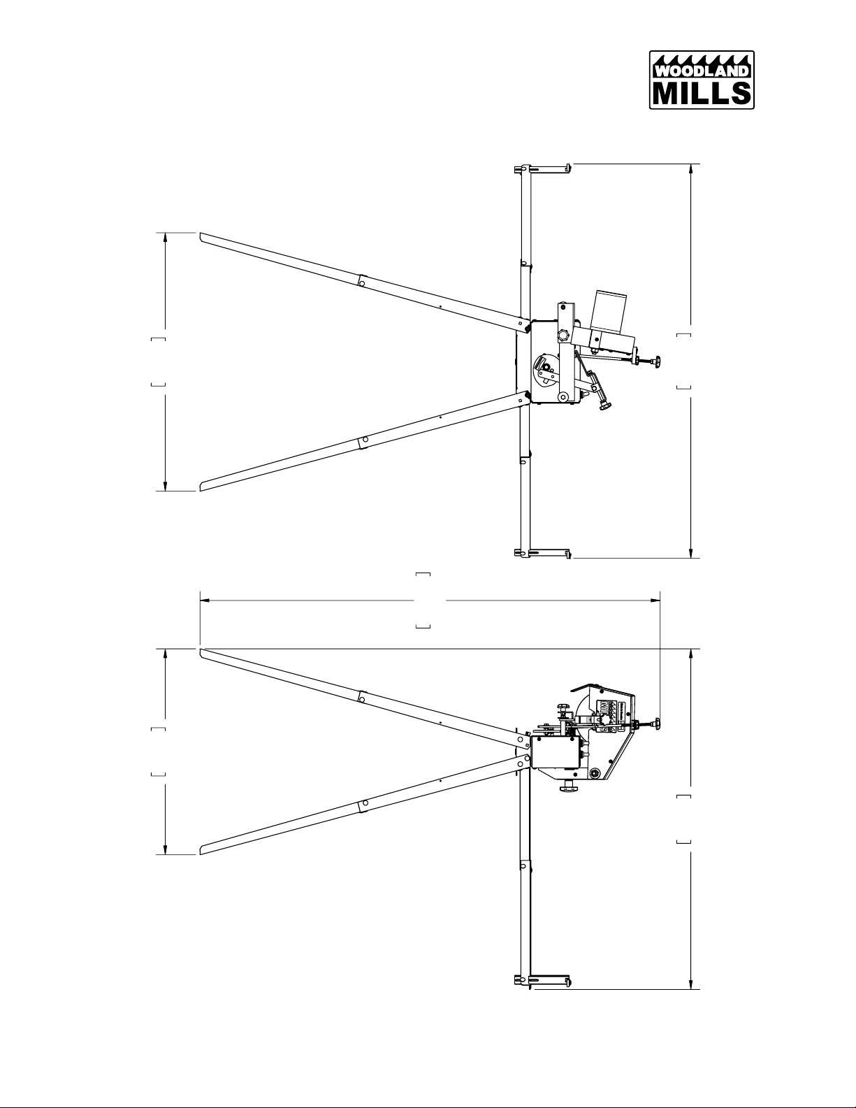
how the bandsaw blade sharpener is used
and maintained and how servicing is to be
carried out. It also describes the measures
to be taken for maximum safety and how the
safety features are designed and function, as
well as how they are inspected, maintained,
and repaired if necessary.
Note: The section dealing with safety
must be read and understood by all those
who install, use, or repair the sharpener.
The operator’s manual comprises installation,
usage, and the maintenance procedures to
be performed by the operator. More
comprehensive servicing or troubleshooting
should not be performed unless instructed by
a service technician.
The operator’s manual describes all the
requisite safety features and should be read
and understood by the user before the
sharpener is assembled.
Symbols and warning signs shown on this
page can be found in this operator’s manual
and on the sharpener. If a decal on the
sharpener has been damaged or is worn, a
new warning decal must be applied as soon
as possible in order to ensure the greatest
possible safety when using the sharpener.
The bandsaw blade sharpener shall only be
used for bandsaw blades with hardened
teeth. The bandsaw blade width shall be
1.25 in [32 mm].
KEY SYMBOLS
MANDATORY ACTIONS
The symbols below used in this operator’s
manual:
WARNINGS
The decal with the symbols below are found
on the bandsaw blade grinder:
BBS-MY2020-EN: Rev A
Page of352
19-May-2020
Read the manual carefully before
attempting to use the bandsaw
blade grinder.
Wear protective gloves.
Wear protective eyewear.
Exercise caution.
Battery polarity warning.

Sharpener Operator’s Manual
SAFETY REGULATIONS
The following safety regulations apply to the sharpener:
•Do not store gasoline/petrol in the vicinity of the sharpener. Sparks from the grinding disc or
the electrical connection could ignite it.
•The bandsaw blade is sharp and can cause injury. Always wear protective gloves when
handling blades.
•The grinding disc must turned off when adjusting the sharpener.
•Ensure the battery polarity connections are correct. The grinding disc could come loose and
cause personal injury if it rotates in the wrong direction.
•Ensure the grinding disc shows no signs of cracking and is secured tightly to the spindle.
Stop the grinding disc immediately if abnormal vibration occurs.
•Always wear protective eyewear while grinding!
TECHNICAL SPECIFICATIONS
Item
Sharpener Specification
Motor
12 VDC
Power Source
12 V Battery (Customer-Supplied)
Blade Width Range
1-¼to 1-½in [32 to 38 mm]
Blade Pitch Range
¾to 1-¼in [19 to 32 mm]
Blade Thickness Range
0.035 to 0.055 in [0.89 to 1.4 mm]
Preset Blade Angles
7°, 10°, 14°
Shipping Weight
29 lb [13.2 kg]
BBS-MY2020-EN: Rev A
Page of452
19-May-2020

Sharpener Operator’s Manual
OVERALL DIMENSIONS
BBS-MY2020-EN: Rev A
Page of552
19-May-2020

Sharpener Operator’s Manual
ASSEMBLY
1. TOOLS REQUIRED
Tool
Specification
Screwdriver
T20 Torx
Wrench/Socket
8 mm
Wrench/Socket
10 mm
Pliers
Min. 2 in [50 mm] grip dia
BBS-MY2020-EN: Rev A
Page of652
19-May-2020

Sharpener Operator’s Manual
2. MOUNTING STYLE
Before starting the assembly decide how the sharpener will be mounted when in use. If utilizing
the stand is desirable from a portability standpoint, proceed to the next section, STAND.
However, if the sharpener would be better utilized secured to a workbench, skip over the
STAND section and start at assembly step, CONTROL BOX.
**Note: The graphics in the manual assume a stand-mount installation but the
instructions will note the assembly differences where applicable.**
BBS-MY2020-EN: Rev A
Page of752
19-May-2020
STAND MOUNT
WORKBENCH MOUNT

Sharpener Operator’s Manual
3. STAND
Using the hardware and components listed below, assemble the stand. If the sharpener will be
mounted directly to a workbench, skip this assembly step and proceed to the next section.
A. LEGS
Assemble the lower leg to the upper leg using two (2) M5 X 12 mm carriage bolts, two (2) M6
flat washers, and two (2) M5 hex nuts. Repeat this for all four (4) legs.
16x
M5 X 12 mm
Carriage Bolt
16x
M6 Flat
Washer
16x
M5 Hex Nut
4x
Upper Leg
16x
M5 Lock Nut
4x
Lower Leg
16x
M5 Wing Nut
1x
Mounting Base
BBS-MY2020-EN: Rev A
Page of852
19-May-2020
Lower leg nests
into upper leg

Sharpener Operator’s Manual
B. LEGS-TO-MOUNTING BASE (FRONT)
With all the legs assembled, fasten the front legs to the mounting base using the following
hardware on each leg: two (2) M5 X 12 mm carriage bolts, two (2) M6 flat washers, one (1) M5
lock nut, and one (1) M5 wing nut.
BBS-MY2020-EN: Rev A
Page of952
19-May-2020
M5 Lock Nut
Carriage bolt with lock
nut passes through
round hole in side of
mounting base

Sharpener Operator’s Manual
C. LEGS-TO-MOUNTING BASE (REAR)
Fasten the rear legs to the mounting base using the following hardware on each leg: four (4) M5
X 12 mm carriage bolts, four (4) M6 flat washers, four (4) M5 hex nuts.
BBS-MY2020-EN: Rev A
Page of10 52
19-May-2020
(4X) M5 Hex Nuts
Rear face of mounting
base has slots for
support arms.

Sharpener Operator’s Manual
The completed stand should now look as shown:
BBS-MY2020-EN: Rev A
Page of11 52
19-May-2020

Sharpener Operator’s Manual
4. CONTROL BOX
Using the hardware and components listed below, assemble the control box to the stand and
the advancer to the control box.
A. CONTROL BOX-TO-STAND
Assemble the control box to the stand using the two (2) M6 X 14 mm hex bolts as shown.
2x
M6 X 14 mm
Hex Bolt
1x
Control Box
Sub-Assembly
1x
M6 Hex Nut
1x
Advancer
Sub-Assembly
BBS-MY2020-EN: Rev A
Page of12 52
19-May-2020

Sharpener Operator’s Manual
B. ADVANCER
Then assemble the advancer sub-assembly to the connecting arm on the control box using one
(1) M6 hex nut. Snug the nut but do not over-tighten.
BBS-MY2020-EN: Rev A
Page of13 52
19-May-2020

Sharpener Operator’s Manual
5. GRINDING HEAD
Begin the grinding head assembly by using the hardware listed below to assemble the grinding
head sub-assembly to the control box.
A. GRINDING HEAD-TO-CONTROL BOX
Assemble the grinding head to the rear of the control box using the M10 X 40 mm knob and
M10 flat washer. Then connect the motor cable to the wiring harness.
1x
M10 X 40 mm
Knob
1x
Grinding Head
Sub-Assembly
1x
M10 Flat
Washer
BBS-MY2020-EN: Rev A
Page of14 52
19-May-2020

Sharpener Operator’s Manual
B. GRINDING DISC
Next, assembly the grinding disc to the grinding head sub-assembly.
Remove the knurled nut from the electric motor and slide the grinding disc onto the shaft.
Replace the nut and tighten it securely using pliers.
1x
Grinding Disc
BBS-MY2020-EN: Rev A
Page of15 52
19-May-2020
Remove knurled nut
from motor before
installing grinding disc.

Sharpener Operator’s Manual
C. DEPTH ADJUSTMENT ROD
Using the hardware listed below, assemble the depth adjustment rod to the grinding head.
Thread the long-threaded end of the rod up through the bracket on the grinding head. Then
thread the thru-hole lock knob, the M6 hex nut, and the upper knob to the top of the rod. Finally,
thread the acorn nut onto the bottom end of the rod. Ensure the distance from the top of the
bracket to the tip of the acorn nut is approx. 7 in [178 mm] for ease of adjustment later.
1x
M6 Hex Nut
1x
Depth
Adjustment
Rod
1x
M6 Acorn Nut
1x
M6 Thru-Hole
Lock Knob
1x
M6 Threaded
Knob
BBS-MY2020-EN: Rev A
Page of16 52
19-May-2020
~7 in
[178 mm]
Bracket
M6 hex nut
acts as jam nut
for upper knob

Sharpener Operator’s Manual
D. GRINDING SHIELD
To finalize the grinding head assembly, secure the grinding shield to the grinding head using the
hardware listed below.
Using a T20 Torx screwdriver, secure the shield to the grinding head as shown.
1x
#8 X 0.375
Torx Self-
Tapping Screw
1x
Grinding Shield
BBS-MY2020-EN: Rev A
Page of17 52
19-May-2020

Sharpener Operator’s Manual
6. SUPPORT ARMS
A. INNER SUPPORT ARMS
Using the hardware and components listed below, assemble the inner support arms to the
sharpener.
Facing the rear of the sharpener, slide the right inner support arm into the cutout in the mounting
base. Then slide the left support arm into the other cutout ensuring the left arm is below the
right arm. Secure both arms to the base and control box using the M6 4-lobe knob.
Note: If mounting the sharpener to a
workbench, fasten the inner support
arms to the mounting base using the
extra M6 X 14 mm hex bolt instead of
the M6 4-lobe knob. See section,
WORKBENCH MOUNTING, for more
information.
1x
M6 4-Lobe
Knob
2x
Inner Support
Arm
BBS-MY2020-EN: Rev A
Page of18 52
19-May-2020
WORKBENCH MOUNTING ONLY
M6 X 14 mm
Hex Bolt
For workbench mounting, replace
knob with M6 X 14 mm hex bolt
Insert arm “1” first,
then arm “2”
1
2
Table of contents
Other Woodland Mills Power Tools manuals
Popular Power Tools manuals by other brands

Hitachi
Hitachi CJ 90VST Technical and service manual

Bavaria
Bavaria BJS 650 E Original operating instructions

RADLEY
RADLEY 1281-914 owner's manual

Drill Master
Drill Master XP user guide

Fayat Group
Fayat Group BOMAG BRP 35/60 D Operating Instruction, Maintenance Instruction

Festool
Festool VS-600 instruction manual