Briggs & Stratton SNAPPER SST-18CL User manual

SNAPPER SST.18CL
POWERED BY
[_BRIGGS & STRAI"rONJ
Owners Manual -Straight Shaft Trimmer
Manual del Propietario -Guadafia de Eje Recto
Manuel d'utilisation - Coupe-bordures _manche droit
SNAPPER
Attn: CUSTOMER RELATIONS
P.O. BOX 777
McDONOUGHT, GA 30253
PHONE: 1-800-935-2967
www.snapper.com
READ THIS MANUAL CAREFULLY
BEFORE PUTTING STRING TRIMMER
INTO OPERATION. STRICTLY OBSERVE
ALL SAFETY RULES.
LEA ESTE MANUAL
CUIDADOSAMENTE ANTES DE PONER
EN OPERACI6N LA GUADANA DE
NYLON. OBSERVE ESTRICTAMENTE
TODAS LAS REGLAS DE SEGURIDAD.
LIRE CE MANUEL ATTENTIVEMENT
AVANT D'UTILISER LE COUPE-
BORDURES. OBSERVER TOUTES LES
RF:GLES DE SI_CURITI_/_, LA LETTRE.
P/N-780059-8/05
ENGLISH, SPANISH, FRENCH
INGLES, ESPANOL, FRANC#S
ANGLAIS, ESPAGNOL, FRAN(_AIS
This unit is intended for occasional use.
Esta unidad est& destinada para uso ocasional.
Cet appareil n'est pr_vu que pour fonctionner occasionnellement.
Model SST-18CL String Trimmer
Shaft style Straight
Shaft length 62.5"
Engine 34cc 4-cycle
Briggs & Stratton
Cuttinc,Iwidth 15" -18"
Line size .095"/2.4 mm
Unit weight 13.2 Ibs
Headtype Bump feed
Starting system Easy starting 4-cycle
Handle type Standard loop
Clutch No
Shoulder harness Yes
Warranty 2 year Consumer
90 day Commercial
Modelo Guadafia de Nylon
Modelo SST-18CL
Tipo Eje Recto
Longituddel Eje 62.5"
Motor De 34cc 4-Tiempos
Brig_ls& Stratton
Ancho del Corte 15" - 18,
Medida del Nylon .095"/2.4 mm
Peso de la Unidad 13.2 libras
Tipo cabezal Alimentado por tope
Sistemade arranque De 4-Tiempos de F61cilArranque
Tipo agarradera Curva cerrada est_.ndar
Embrague .No
Arn_s Sf
Garanfia 2 afios Uso Privado
90 dfas Uso Comercial
Modble Taille-bordure bfil SST-18CL
Type de manche Droit
LOn_lueurdu manche 62.5"
Moteur 34 cm3,4 temps
Briggs & Stratton
Largeur de coupe 15"- 18"
Dimensiondu fil 2,4 mm
Poids 5,8 kg
Type de t_te Alimentation par frappe au sol
Systbmededdmarraqe 4 temps, d6marrage facile
Type de poign_e Boucle standard
Embraya_le Non
Harnais d'_paule Oui
Garantie 2 ans pour usage priv6
90 jours pour usage commercial
PRINTED IN U.S.A.

Engine/Motor/Moteur
I10014
10015
10O17
10016
100__ 10033
100_
10235
1ooo11
10002
1O025
10009
10O07
! t 10069
@
10012
_ 10026
10021
10023
@
10022

SEE FIG.
STRAIGHT SHAFT TRIMMER SST-18CL
Part Number
10000
10001
10002
10003
780059
10007
10009
10010
10011
10012
10013
10014
10015
10016
10017
10018
10021
10022
10023
10025
10026
10031
10032
10033
10041
10042
10043
10052
10053
10069
10235
10236
Engine
Model Used On
SST-BC/SST-18CL/SST-16CL
SST-18CL
SST-18CL/SST-16CL
SST-18CL
SST-18CL
SST- 18CL
SST-18CL
SST-BC/SST-18CL
SST-18CL
SST-i 8CL
SST-18CL
SST-16CL/SST-18CL/SST-BC
SST-18CL
SST-18CL
SST-18CL
SST-18CL
SST-18CL
SST-18CL
SST- 18CL
SST-18CL/SST-16CL
SST-18CL/SST-16CL
SST-I,8CL/SST-16CL
SST-18CL
SST-18CL
SST-BC/SST-18CL
SST-BC/SST-18CL
SST-18CL
SST-18CL/SST-16CL
SST-18cL/ssT-16CL
SST-18CL/SST-16CL
Quantity
1
1
1
1
1
1
1
1
1
1
!
1
2
1
1
1
2
2
1
2
11
1
1
1
1
1
1
2
3
'31
Description
Decal for pipe
Pipe assembly
Label
Pipe assemblywithoutflex shaft
Owner'smanual
Boltfor gear case clamp
Plasticgear case hood
Regularflexible shaftwithstopper
Gearcase 3 bearingwithoutholderand cover
,HolderA
Guardassembly
Nose cone A
Nosecone B
Nosecone screws
Engineclampassembly
Protectorwithoutblade
Bladeto cutnyloncode
Boltsfor blade
Nutsfor blade
Clamp for guard
Boltsfor clamp
Tap and go withdiameter0.095"
Single type lever
On/Off switch
Cable, throttle
Handle assembly
Handle
Hanger assembly
Harness assembly
Bolts
Screws'for loop handle
Nutsfor loop handle
Engine 34cc 4-cycle Briggs & Stratton, Model 21032 0118 E1
SST-18CLTechnical Data Information
Masswithoutfuel, cuttingattachment,guards: ............................................. 5.357 kg
FuelTankVolume: ................................................................... 296 cm3
Maxengine performance: ............................................................. 0.746 kW
Max rotationalfrequencyofthe spindle: .................................................. 6324 RPM
Enginespeedat maximumspindlefrequency: ............................................. 8600 RPM
Enginespeedat idle: ................................................................. 3600 RPM
Fuelconsumption: ................................................................... 0.399 kg/h
Specificfuel consumption: ............................................................. 542 g/kWh
Vibrationlevelsfor idlingand racing: ...... Wide OpenThrottle"racing" ............ Idle
LeftHand= 6.59 m/s2LeftHand= 6.53 m/s2
RightHand= 7.05 m/s2RightHand= 3.81 m/s=
Soundpressure levels: ............................................. OperatorEar LpdB(A) = 96.52
WARNING: IT S UNSAFE TO USE ANY AFTER MARKET HEAD,
ATTACHMENT, ACCESSORY OR BLADE ON THIS UNIT. USE
ONLY HEADS, ATTACHMENTS, BLADES AND ACCESSORIES
MANUFACTURED BY SNAPPER AND INTENDED FOR THIS
SPECIFIC MODEL.

CONTENTS PAGE
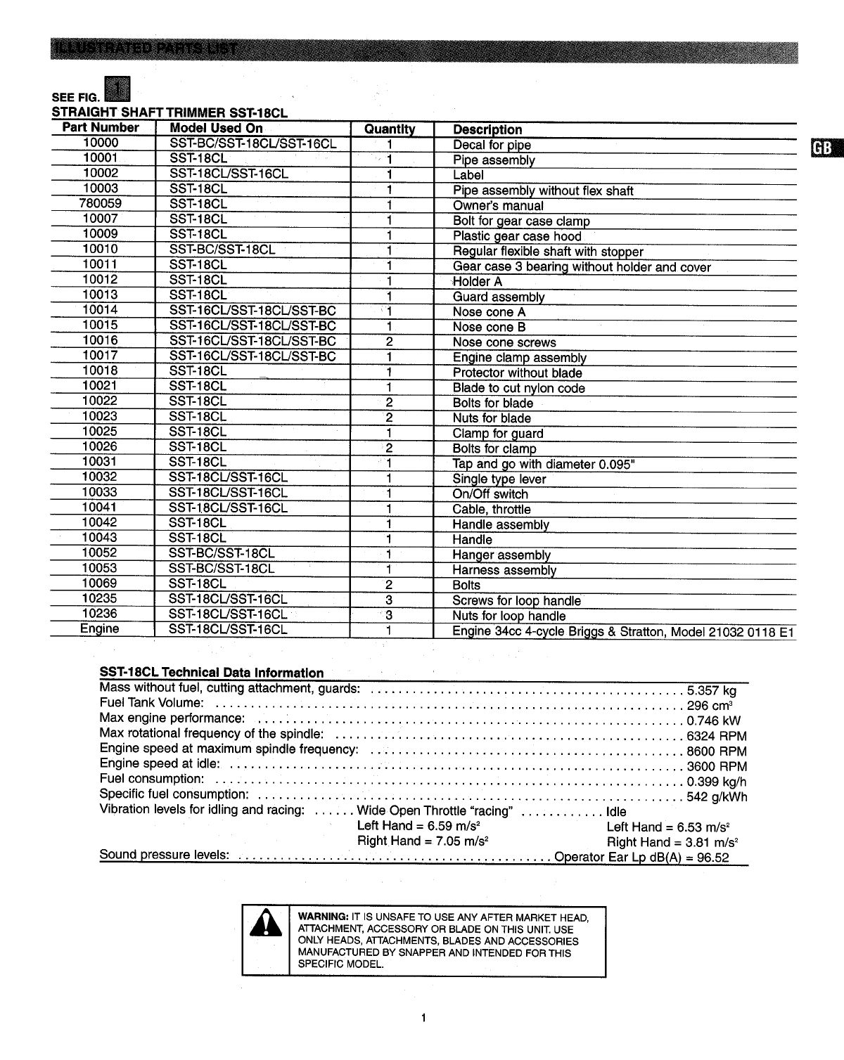
ILLUSTRATED PARTS LIST ........... '............. 1
SAFETY RULES ................................. 2
ASSEMBLY ..................................... 3
OPERATION ..................................... 4
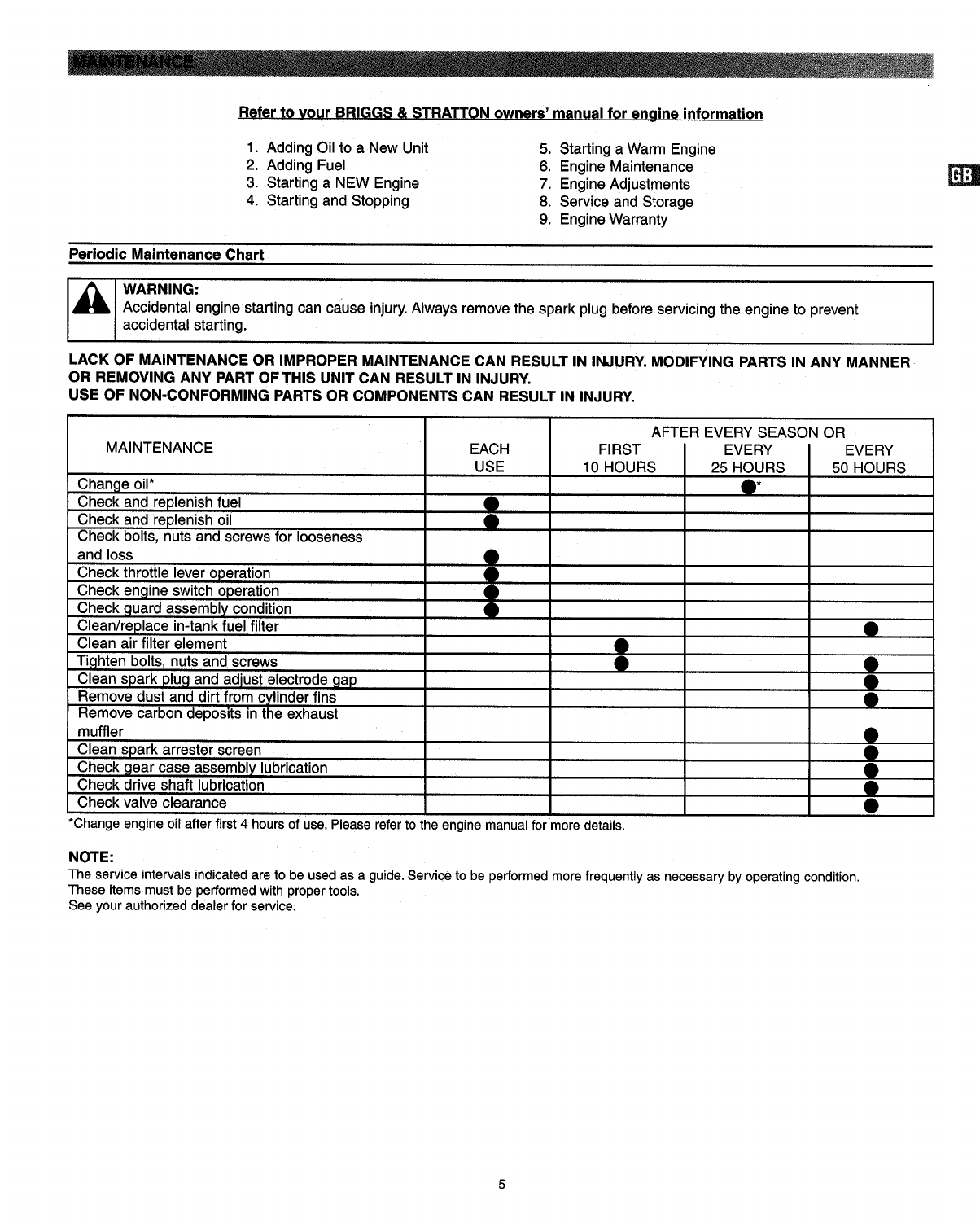
MAINTENANCE .................................. 5
SERVICE/ADJ USTM ENTS ......................... 6
TROUBLESHOOTING ............................. 7
STORAGE ....................................... 7
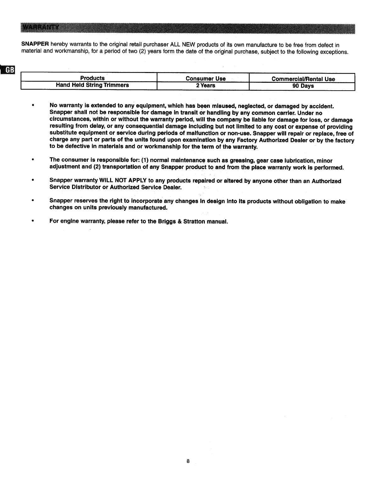
WARRANTY INFORMATION ........................ 8
SAFETY AND INTERNATIONALSYMBOLS
Thisoperator'smanualdescribessafetyand international
symbolsand pictographsthatappearon thisproduct.Read the
operator'smanualfor completesafety,assembly,operating,
maintenanceand repairinformation,
SYMBOL MEANING
• SAFETY ALERT SYMBOL
Indicatesdanger,warningor
caution.Maybe usedin conjunction
withothersymbolsorpictogrephs.
•WARNING - READ OPERATOR'S
MANUAL
Read the operator's manual(s) and
follow all warnings and safety
instructions. Failure to do so can
result in serious injury to the
operator and/or bystanders.
• WARNING: Never use blades or
Donotinstall flailing devices, This unit is
anytype ofblade designed for line trimmer use only,
onthisUnit. Use of any other accessories or
attachments will increase the risk
of injury.
•Do not allow a person to use this unit unless instructions are
read and understood. Never allow children to operate or play
with the unit.
•Do not operate this unit when tired, illor under the influence of
alcohol, drugs, or medication.
Alwayswear heavy,long pants, boots, gloves, and a long
sleeveshirt.Do notwearlooseclothing,jewelry,shortpants,
sandals,or go barefoot.Securehairso itisabove
shoulderlevel.
Inspect unitbefore eachuse. Replacedamaged parts. Check
for fuel leaks.Makesure allfasteners are inplaceand secure.
Replacecuttingattachmentpartsthatarecracked,chipped,
or damagedinany way.Makesurethe cuttingattachmentis
properlyInstalledand securelyfastened. Besurethe cutting
attachmentshieldis properlyattached,and inthe position
recommendedbythe manufacturer.Use onlyflexible, non-
metalliclinerecommendedbythemanufacturer.Neveruse,
for example,wire orwire-ropewhichcan breakoffand
becomea dangerousprojectile.
•Keepfirm footing andbalance.Do not over-reach:Keepcutting
attachmentbelowwaistlevel.Keepall partsofyourbodyaway
from therotatingcuttingattachmentandhotsurfaces.
• Neverstartor runtheunitinsidea closedroomor building;
breathingexhaustfumescankill.
WEAR EYE AND HEARING
PROTECTION •
WARNING: Thrownobjectsand
loudnoisecan causesevereeye
injuryand hearingloss.Wear eye
protectionmeetingANSI Z87.1
standardsandear protectionwhen
operating this unit.Use a full face •
shieldwhen needed.
KEEP BYSTANDERS AWAY
WARNING: Keep all bystanders,
especially children and pets, at
least 50 feet (15m) from the
operating area,
•THROWN OBJECTS AND
ROTATING CUTTER CAN
CAUSE SEVERE INJURY
WARNING: Do not operate without
the cutting attachment shield in
place. Keep away from the rotating
cutting attachment.
Pour fuel outdoors where there are no sparks and flames.
Slowly remove the fuel cap only after stopping the engine. Do
not smoke while fueling. Wipe spilled fuel from the unit. Move
at least 10 ft. (3 m) away from the fueling source and site
before starting engine.
Clear the area to be cut before each use. Remove all objects
such as rocks, broken glass, nails, wire, or string which can
be thrown or become entangled in the cutting attachment.
Clear the area of children, bystanders and pets. At a
minimum, keep all children, bystanders and pets outside a
50 ft. (15 m) radius; outside the 50 ft. zone, there is still a risk
of injury to bystanders from being struck with the moving
strings in the event of a cutting lines thrust or other
unexpected reaction of the saw.
The cutting attachment may be spinning during carburetor
adjustments. Wear your protective equipment and observe all
safety instructions. When the unit is turned off make sure the
cutting attachment has stopped before the unit is set down.
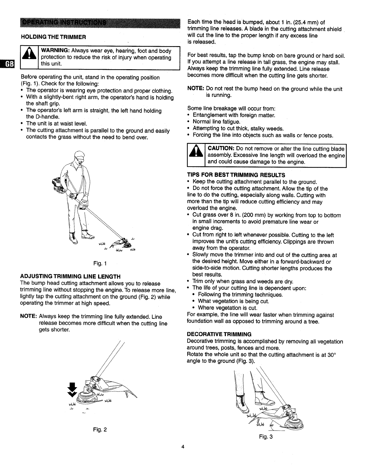
• The handles and shield must be mounted according to the
instructions. The unit is designed to be used while positioned
on the right side.

•TOOL LIST
•Screwdriver (Phillips or Standard)
•Allen wrench 4ram
•INSTALLING CUTTING HEAD
•Lock gear box by inserting a pin thru hole and finding
corresponding notch.
•To install head, turn counterclockwise. Hand-tighten head
securely.
•To remove head, turn clockwise.
INSTALLING DEBRIS GUARD
The top clamp is fixed to the tube in the proper position.
Attach the debris shield to the clamp with the two screws
and hardware provided. Tighten the attaching screws firmly.
•STOP AND START SWITCH
1. Ignition switch
2. Stop
3. Start
INSTALL ASSIST HANDLE
Use the 3 screws provided for this assembly, Mount the
back edge of the handle clamp to match the arrow on the
tube. Adjust the handle for comfort and good balance.
Check that the cutting line of the unit is away from your feet
and legs.
•SHOULDER HARNESS
•Placethestrapoveryourleftshoulderand attachclipto
clampeyeon shafttube.
•Loosenclampscrewandslideclampupor downuntilunit
balanceswithheadjusttouchingthe ground.
•Tightenscrew.

HOLDING THE TRIMMER
I_ I WARNING: Always wear eye, hearing, foot and body
r
protection to reduce the risk of injury when operating
this unit.
Before operating the unit, stand in the operating position
(Fig. 1). Check for the following:
•The operator is wearing eye protection and proper clothing.
• With a slightly-bent right arm, the operator's hand is holding
the shaft grip.
• The operator's left arm is straight, the left hand holding
the D-handle.
•The unit is at waist level.
• The cutting attachment is parallel to the ground and easily
contacts the grass without the need to bend over.
Fig. 1
ADJUSTING TRIMMING LINE LENGTH
The bump head cutting attachment allows youto release
trimminglinewithoutstoppingthe engine.To releasemoreline,
lightlytapthe cuttingattachmenton theground(Fig.2) while
operatingthetrimmerat highspeed.
NOTE: Always keep the trimminglinefully extended. Line
release becomesmoredifficultwhen thecuttingline
getsshorter.
Eachtime the head is bumped, about 1in. (25.4 ram) of
trimming line releases. A blade in the cutting attachment shield
will cut the line to the proper length if any excess line
is released.
rFor best results, tap the bump knob on bare ground or hard soil.
If you attempt a line release in tall grass, the engine may stall.
Always keep the trimming line fully extended. Line release
becomes more difficult when the cutting line gets shorter.
NOTE: Donot restthebump head on the ground while the unit
isrunning.
Some line breakage will occur from:
• Entanglement with foreign matter.
• Normal line fatigue.
•Attempting to cut thick, stalky weeds.
• Forcing the line into objects such as walls or fence posts.
CAUTION: Do not remove or alter the line cutting blade
assembly.Excessivelinelengthwilloverloadtheengine
andcouldcause damageto theengne.
TIPS FOR BESTTRIMMING RESULTS
•Keep the cutting attachment parallel to the ground.
• Do notforce the cutting attachment. Allow the tip of the
line to do the cutting, especially along walls. Cutting with
more than the tip will reduce cutting efficiency and may
overload the englne.
• Cut grass over 8 in. (200 mm) by working from top to bottom
in small increments to avoid premature line wear or
engine drag.
• Cut from right to left whenever possible. Cutting to the left
improves the unit's cutting efficiency. Clippings are thrown
away from the operator.
• Slowly move the trimmer into and out of the cutting area at
the desired height. Move either in a forward-backward or
side-to-side motion. Cutting shorter lengths produces the
best results.
• Trim only when grass and weeds are dry.
• The life of your cutting line is dependent upon:
• Following the trimming techniques.
• What vegetation is being cut.
• Where vegetation is cut.
For example, the line will wear faster when trimming against
foundation wall as opposed to trimming around a tree.
DECORATIVETRIMMING
Decorative trimming isaccomplished byremoving all vegetation
aroundtrees, posts,fences and more.
Rotatethewholeunitso thatthe cuttingattachmentisat 30°
angletothe ground(Fig.3),
Fig. 2 Fig. 3

Refer to your BRIGGS & STRATTON owners' manual for engine information
1. Adding Oil to a New Unit
2. Adding Fuel
3. Starting a NEW Engine
4. Starting and Stopping
5. Starting a Warm Engine
6. Engine Maintenance
7. Engine Adjustments
8. Service and Storage
9. Engine Warranty
Periodic Maintenance Chart
I klw...,.o
Accidental engine starting can cause injury. Always remove the spark plug before servicing the engine to prevent
accidental starting.
LACK OF MAINTENANCE OR IMPROPER MAINTENANCE CAN RESULT IN INJURY. MODIFYING PARTS IN ANY MANNER
OR REMOVING ANY PART OFTHIS UNIT CAN RESULT IN INJURY.
USE OF NON-CONFORMING PARTS OR COMPONENTS CAN RESULT IN INJURY,
MAINTENANCE
Change oil*
Check and replenish fuel
Check and replenish oil
Check bolts, nuts and screws for looseness
and loss
Check throttle lever operation
Check engine switch operation
Check guard assembly condition
Clean/replace in-tank fuel filter
Clean air filter element
Tighten bolts, nuts and screws
Clean spark plug and adjust electrode _lap
Remove dust and dirt from cylinder fins
Remove carbon deposits in the exhaust
muffler
Clean spark arrester screen
Check gear case assembly lubrication
Check drive shaft lubrication
Check valve clearance
EACH
USE FIRST
10 HOURS
$
IEVERY
25 HOURS
AFTER EVERY SEASON OR
IEVERY
50 HOURS
.
*Change engine oil after first 4 hours of use. Please refer to the engine manual for more details. i
NOTE:
The service intervals indicated are to be used as a guide. Service to be performed more frequently as necessary by operating condition,
These items must be performed with proper tools.
See your authorized dealer for service.

LINE REPLACEMENT
SAFETY RULES
1. Shutdown thetrimmerto makecertainthe headcannot
turnwhileworkingwiththehead.
2. Checkmountingofcuttinghead ontrimmerandtightenif it
isloose.
3. Inspectheadfor wear,chipsor cracks.Replacepartsor
entirehead ifneeded.
4. Alwaysuselinethatisthe correctdiameterandtypefor this
unit.Donot usemetalreinforcedor metalline.
5. Make surethetwo retainingpawlsspreadouttothe
peripheryofthecoverwindows.
6. Checkthe headfor deflectionor abnormalnoisebyrotating
the headby hand.Deflectionor abnormalnoisemaycause
vibrations,whichwillcausethecuttinglinetoweldtooether.
It isalso potentiallydangerous.
®
I4.7 in.
(_ (12cm)
4.0 in. (_)
(locrn)
X
O
®
®
REFILLING TRIMMING LINE
1. Forreplacementline, use adiameter of .095 in. (2.4 mm).
The spooliscapablefor a lineupto20 ft. (6 m) on the4 in.
head.Avoidusinga largerlineas itmaycutdownthe
trimmingperformance.
2. Pinchthe slottedarea onthe bothsidesofthespool
housingto unhookthe bottomcap.
3. Takeoutthespooland pullofftheoldline. Putone endof
newline throughthe spoolholesand pullituntilthe length
isequalbetweeneachpart oftheline.
4. Windupthe lineinthecorrectdirectionas indicatedonthe
spool.
5. Hookeachendofthe lineinthesloton the edgeofthe
spool,and thenputthe endsthroughthe eyeletsonthe
housing.Makesurethatthe springand thewashersare in
place.
6. Whileholdingthe spool against thehousing,pullthe line
endsto releasethemfrom theslot.
7. Lineupthe sloton the bottomcapwiththehookon the
housing,pressthe capagainstthehousinguntilitclicks.

Case1.Startingfailure '
CHECK PROBABLE CAUSES ACTION
Fuel tank --) Incorrect fuel --) Drain it and fill with correct fuel
Fuel filter --) Fuel filter isclogged -) Clean
Carburetor idle speed screw -) Out of normal range --) Adjust to normal range
No spark ") Spark plug is fouled/wet -) Clean/dry
-') Plug gap is incorrect -) [Correct GAP .025" (0,6~0.7 mm)]
Spark plug -') Disconnected -') Retighten
Case 2. Engine starts but does not keep running/Hard re-starting
CHECK PROBABLE CAUSES
Fuel tank -) Incorrect fuel or stale fuel
Carburetor idle speed screw -) Out of normal range
Muffler, cylinder(exhaust port) -) Carbon is built-up
Air cleaner -) Clogged with dust
Cylinder fin, fan cover -') Clogged with dust
ACTION
") Drain it and fill with correct fuel
-) Adjust to normal range
•..) Wipe away
•..) Wash
-) Clean
If your unit needs further service, please consult with an authorized service dealer in your area.
_' WARNING: Performthe following stepsafter each use:
•Allow engine to cool, and secure the unit before storing
or transporting.
• Store unit and fuel in a well ventilated area where fuel vapors
cannot reach sparks or open flames form water heaters,
electric motors or switches, furnaces, etc.
• Store unit with all guards in place. Position unit so that any
sharp objects cannot accidentally cause injury.
• Store unit and fuel well out of the reach of children.
SEASONAL STORAGE
Prepare unit for storageat end of seasonor ifitwill notbe used
for 30 daysor more.Ifyourunitistobe storedfor a period
of time:
•Drainall fuel from thefuel tank intotheproperreceptacles
for storage.
•Presspurgebulb15 timesto removeall fuel from carburetor
and fuel lines.Drainthisfuel intoproperreceptacles.Iffuel is
tobe disposed,please referto localrulesfor properdisposal.
•Clean theentireunitbeforelengthystorage.
•Store ina clean dry area.
•Lightlyoilexternalmetalsurfaces.
•Thistrimmermay be storedina varietyof positions.If
possible,itispreferredto storethetrimmerina horizontal
positionwiththespark plugup.The trimmershouldnotbe
storedor transportedwiththespark plugdown.
•Storingortransportingthe trimmerwiththe sparkplugdown
may resultinwhitesmokecomingfrom the muffleror
difficulty starting.
ENGINE
•Removesparkplug and pour 1 teaspoonof HD30 wt.engine
oilthroughthe sparkplugopening.Slowlypullthe starterrope
8 to 10 timesto distributeoil.
•Replacesparkplugwithnewoneof recommendedtypeand
heatrange.
•Clean airfilter.
•Checkentireunitfor loosescrews,nuts,and bolts.Replace
any damaged,broken,orwornparts.
• At the beginningof thenextseason,useonlyfresh fuel.
OTHER
• Do not storegasoline from one seasontoanother.
•Replaceyourgasolinecan ifitstartsto rust.
•When removingtheunitfrom storage,onlyusefresh gasoline.
Performthe routineoperationchecksas spelledout inthe
manualbeforeanystart.
FUEL SYSTEM
Fuel stabilizer is an acceptable alternative in minimizing the
formation of fuel gum deposits during storage. Add stabilizer to
the gasoline in the fuel tank or fuel storage container, Follow the
mix instructions found on stabilizer container. Run engine at
least 5 minutes after adding stabilizer.

SNAPPERhereby warrants to the original retail purchaser ALL NEW products of its own manufacture to be free from defect in
material and workmanship, for a period of two (2) years form the date of the original purchase, subject to the following exceptions,
Products
Hand Held String Trimmers II
Consumer Use Commercial/Rental Use I
2Years 90 Days I
No warranty is extended to any equipment, which has been misused, neglected, or damaged by accident.
Snapper shall not be responsible for damage in transit or handling by any common carrier. Under no
circumstances, within or without the warranty period, will the company be liable for damage for loss, or damage
resulting from delay, or any consequential damage including but not limited to any cost or expense of providing
substitute equipment or service during periods of malfunction or non-use. Snapper will repair or replace, free of
charge any part or parts of the units found upon examination by any Factory Authorized Dealer or by the factory
to be defective in materials and or workmanship for the term of the warranty.
The consumer is responsible for: (1) normal maintenance such as greasing, gear case lubrication, minor
adjustment and (2) transportation of any Snapper product to and from the place warranty work is performed.
Snapper warranty WILL NOT APPLY to any products repaired or altered by anyone other than an Authorized
Service Distributor or Authorized Service Dealer.
Snapper reserves the right to incorporate any changes in design into its products without obligation to make
changes on units previously manufactured.
For engine warranty, please refer to the Briggs & Stratton manual.

Numerodeparte
10000
10001
10002
10003
78OO59
VEA LA FIG.
GUADAI_IA DE EJE RECTO MODELO SST-18CL
Modelo Usado En
SST-BC/SST-18CL/SST-16CL
SST-18CL
SST-18CL/SST-16CL
.SST-18CL
10007
10009
10010
10011
10012
10013
10014
10015
10016
10017
10018
10021
10022
10023
10025
10026
10031
10032
10033
10041
10042
10043
10052
10053
10069
10235
10236
Motor
SST- 18CL
SST-18CL
SST-18CL
SST-BC/SST- 18CL
SST-18CL
SST-18CL
SST-18CL
SST-16CL/SST-18CL/SST-BC
SST-18CL
SST-18CL
SST-18CL
SST-18CL
SST-18CL
SST-18CL
SST- 18CL
SST-18CL/SST-16CL
SST-18CL/SST-16CL
SST- 18CL/SST- 16CL
SST-18CL
SST-18CL
SST-BC/SST-18CL
SST-BC/SST-18CL
SST-18CL
SST-18CL/SST-16CL
SST-18CL/SST-16CL
SST-18CL/SST-16CL
Cantidad
1
1
.11
1
1
1
1
1
1
1
1
1
2
1
1
1
2
2
1
2
1
1
1
1
!
1
1
1
1
3
3
1.'
Descrlpcl6n
Calcoman;a para el tubo
Coniunto tubo
Etiqueta
Coniunto tube sin eie flexible
Manual del propietario
Perno para abrazadera - caia encjranaie
Tapa caja de engranaje - pl_.stica
Eje flexible regular con tapbn
Caja de engranaje de 3 bujes sin soporte ni cubierta
Soporte A
Conjunto protector
Cono delantero A
Cono delantero B
Tornillo cono delantero
Conjunto sujetador motor.
Protector
CuchUla para cortar el codo de nylon
Perno para la cuchilla
Tuerca para la cuchilla
Sujetador para el protector
Perno para el sujetador
Porta nylon con didmetro de 0.095"
Palanca tipo _ni¢o
Suiche de Encendido y Apagado
Cable acelerador
Coniunto agarradera
Manija
Conjunto de suspensibn
Conjunto arn_s
Perno
Tornillos para la agarradera
Tuercas para la agarradera
Motor Briggs & Stratton de 34cc 4-tiempos, Modeto 21032 0118 E1
m
SST-18CL Datos de Informaci6n T6cnica
Masa sin combustible, aditamento de corte, protectores: ..................................... 5.357 kg
Volumen Tanque de Combustible: ....................................................... 296 cm3
Maximo Desempefio del Motor: ......................................................... 0,746 kW
Maxima Frecuencia Rotacional del Eje: ................................................... 6324 RPM
Velocidad del Motor a la M&xima Frecuencia del Eje: ........................................ 8600 RPM
Velocidad del Motor en Minima: ........................................................ 3600 RPM
Consumo de Combustible: ............................................................. 0,399 kg/h
Consumo Especffico de Combustible: .................................................... 542 g/kWh
Niveles de Vibraci6n para Velocidad de Ralentf y de aceleraci6n mdxima:
....... Acelerador Totalmente Abierto "de aceleraci6n mdxima". ............... Ralentf
Izquierda = 6.59 m/s2Izquierda = 6.53 m/s2
Derecha = 7.05 m/s2 Derecha = 3.81 m/s2
Niveles de presi6n de sonido: . .............................. Audici6n del Operador Lp dBIA ) = 96.52
ADVERTENCIA: ES PELIGROSO USAR EN ESTA UNIDAD
CUALQUIER CABEZAL, ADITAMENTO, ACCESORIO O CUCHILLA
QUE SE CONSIGA EN EL MERCADO SECUNDARIO. USE 0NICA-
MENTE LOS CABEZALES, ADITAMENTOS, CUCHILLAS Y ACCE-
SORIOS FABRICADOS POR SNAPPER Y DESTINADOS PARA
ESTE MODELO ESPEC[FICO.

CONTENIDO P__._GINA
LISTA DE PARTES ILUSTRADAS .......... '. .............. 9
PAUTAS DE SEGURIDAD .............................. 10
MONTAJE ........................................... 11
OPERACI(_N ........................................ 12
MANTENIMIENTO .................................... 13
SERVIClO/AJUSTES .................................. 14
DETECCION DE FALLAS .............................. 15
BODEGAJE .......................................... 15
INFORMAClON DE GARANTIA .......................... 16
S|MBOLOS INTERNACIONALES DE SEGURIDAD
Este manual del operador describe los simbolos y pictografias interna-
cionales y de seguridad que aparecen en este producto. Lea et manual
del operador para obtener informaci6n completa de seguridad, instala-
ci6n, operaci6n, mantenimiento y reparaci6n.
SiMBOLO SIGNIFICADO
•S|MBOLO DE ALERTA DE
SEGURIDAD
Indica peligro, advertencia o precauci6n.
Puede ser usado junto con otros
simbolos o pictograflas.
•ADVERTENCIA - LEA EL MANUAL
DEL OPERADOR
Lea el (los) manual(es) del operador
y siga todas las instrucciones de
advertencias y seguridad. Dejar de
hacerlo puede ocasionar lesiones
graves el operador y/o alas personas
que se encuentren cerca.
•PROTECCl6N PARA LOS OJOS Y
LOS OIDOS
ADVERTENClA: Los objetos lanzados
y el fuerte ruido pueden ocasionar
lesiones graves en los ojos y la p6rdida
de la audici6n. Prot_jase los ojos
cumpliendo con la norma ANSI Z87.1 y
utilice protecci6n en los ofdos cuando
opere esta unidad. Use una careta
protectora que cubra completamente
la cara cuando sea necesario.
•MANTENGA A DISTANCIA LOS
CURIOSOS
ADVERTENCIA: Todos las personas
que se encuentren cerca, especialmente
los ni_os y las mascotas, deben mante-
nerse auna distancia de por Io menos
50 pies (15m) del drea de operaci6n.
•LOS OBJETOS LANZADOS Y EL
ADITAMENTO GIRATORIO DE CORTE
PUEDEN OCASlONAR SERIAS
LESlONES
ADVERTENClA: No opere ia m&quina
sin el protector del aditamento de corte
en su lugar. Proteja todo el aditamento
giratorio de corte.
No instale ningOn
tipo de cuchilla en
esta unidad.
•ADVERTENClA:Nunca use cuchillas
ni dispositivos que golpeen. Esta unidad
estddiseSadaL_nicamenteparael uso
de la guadahade nylon.Elusode otros
accesorioso aditamentosincrementard
elriesgode una lesi6n.
•No permita que cualquierpersona utiliceesta unidada menos que
hayalefdoy comprendidosusinstrucciones.Nuncadeje que losnihos
operenojueguenconla unidad.
• No opere esta unidadcuando se sientacansado,este enfermo ni bajo
lainfluenciadelalcohol,drogaso cualquiermedicamento.
•Usesiemprepantalones largosresistentes,botas, guantes y una
camisade mangalarga.Nouseropafloja, pantalonescortos,sanda-
l|asni sedescalce.Aseguresu cabellosiIo usaporencimadel nivel
del hombro.
•Inspeccione la unidad antes de cada uso. Cambie las partes que esten
daSadas. Compruebe si hay fugas de aceite. AsegOrese que todos los
sujetadores est6n asegurados yen posici6n. Cambie las partes del
aditamento de corte que estds rajadas, astilladas o daSadas de alguna
manera. AsegOrese que el aditamento de corte est_ correctamente
instalado y asegurado firmemente. Aseg_rese que el protector del
aditamento de corte est_ colocado apropiadamente, yen la posici6n
recomendada por el fabricante. Use _nicamente el nylon flexible, no
metdlico recomendado por el fabricante. Nunca use, por ejemplo,
alambre o cable metdlico los cuales puedan reventarse y Ilegar a
convertirse en un proyectil peligroso.
• Adopte una posici6n firme y balanceada. No se exceda. Mantenga el
aditamento de corte por debajo del nivel de la cintura. Mantenga todas
las partes de su cuerpo a distancia del aditamento de corte y de las
superficies calientes.
• Nunca le de arranqueala unidadnila opereen un lugarencerradoni
dentrode unedificio;respirarlosgasesde escapepuedeocasionarla
muerte.
• Vierta el combustibleen exteriores donde no haya presencia de
chispasni llamas.Remuevalentamentela tapa de combustiblesolo
despu6sde haberdetenidoel motor.Nofume mientras aprovisiona
con combustible.Limpieel combustiblederramadode la unidad.
Apdrtese por Io menos10 pies (3 m) del sitioy lafuentedonde
se aprovision6con combustibleantesde darlearranqueal motor.
•Despeje el drea que va a ser cortada antes usar la unidad, Remueva
todos los objetos tales como rocas, cristal roto, clavos, alambres, o
cuerdas los cuales puedan alcanzar a ser lanzados o enredarse en
el aditamento de corte. Despeje el drea de niSos, personas que se
encuentren cerca y an|males dom_sticos. Haga que todos los nihos,
las personas que se encuentren cerca y los an|males dom_sticos se
aparten en Io posible a un radio de 50 pies (15 m); a una zona apar-
tada de 50 pies, aDn existe el riesgo de que las personas que se
encuentren cerca sean golpeadas con pedazos de cuerda en movi-
miento en el evento de que el nylon de corte se introduzca o que se
presente cualquier otra reacci6n inesperada de la mdquina de corte.
•Eladitamentode cortedebe estar girando durante los ajustesdel
carburador.Prot_jaseconsu equipode proteccibny observetodaslas
instruccionesde seguridad.Cuando apaguela unidadaseg_reseque
el aditamentode cortehaya paradoantesde asentar launidad.
•Lasagarraderasy el protector deben ser instaladosde acuerdo con
las instrucciones.La unidadestddisehadapara set usadamientras
queest_ colocadaen elladoderecho.
10

•LISTA DE HERRAMIENTAS
• Destornillador (Phillips o Est&ndar)
• Llave Allen de 4mm
•INSTALACI(_N DEL CABEZAL DE CORTE
•Asegure la caja del mecanismo de engransje insertando un pin a
tray, s del orificio yencontrsndo la muesca correspondiente,
•Pars instalar el cabezal, girelo en sentido contrsrio el de Iss agujss
del reloj. Apri_telo firmemente con Is mano.
•Pars remover el cabezal, glrelo en $entido de Iss agujss del reloj.
INSTALACI6N DE LA AGARRADERA DE AYUDA
Use los 3 tornillos que vienen pars este conjunto. Instsle el b0rde
trssero del sujetador de Is sgarradera pars que se scople con Is
flecha en el tubo, Ajuste Is agarrsdera pars confortabUidad y buen
equilibrio. Compruebe que el nylon de corte de Is unidad est_ a
distancia de sus piernas ypies.
INSTALACI(_N DEL PROTECTOR DE DESECHOS
El sujetador superior viene fijo al tubo en la posici6n apropiada.
Sujete el protector de desechos al sujetador con los dos tornillos
y los sccesorios suministrados Apriete firmemente los tornillos de
sujeci6n
•SUICHE DE ENCENDIDO Y APAGADO
I. Sulchede Encendido
2. Parsda
S. Encendido
•ARNES
• Coloque Is correaporencimade su hombro izquierdoysujete
Is pinza con la gufa de sujeci6n en el tubo del eje
•Afloje el tornillo del sujetador y deslice el sujetador hacia arriba
o hacia abajo hasta que la unidad se balancee con el cabezal
apenas tocando Is tierra
• Apriete el tornillo
11

COMO SOSTENER LA GUADANA
I_, IADVERTENClA: Prot_jase siempre los ojos, los oidos, los
I
Ipies y el cuerpo para reducir el riesgo de lesiones mientras
opera esta unidad.
Antes de operar la unidad, adopte una postura para la operaci6n
(Fig. 1). Verifique Io siguiente:
•Que el operador est6 protegidndose los ojos y que est_ usando la
ropa adecuada.
•Que con el brazo derecho ligeramente doblado, la mano del operador
est_ sosteniendo la agarradera del eje.
•Que el brazo izquierdo del operador est_ derecho sosteniendo la
manija en D.
•Que la unidad est_ al nivel de la cintura.
•Que el aditamento de corte est_ paralelo con la tierra y que toque
f_cilmente la grama sin la necesidad de inclinarse.
Fig. 1
AJUSTE DE LA LONGITUD DEL NYLON DE CORTE
El aditamento de corte con cabezal de tope le permite aflojar el nylon
de corte sin detener el motor. Para desatar mds nylon, golpee ligera-
mente el aditarnento de corte en la tierra (Fig. 2) mientras opera la
guada_a a alta velocidad.
NOTA: Mantenga siempre el nylon de corte completamente extendido.
Desatar el nylon se hace mds dificil cuando el nylon de corte se
vuelve mds corto.
Cada vez que el cabezal es golpeado, se desata aproximadamente
1 pulgada (25.4 mm) deL nylon de corte. Una cuchilla en el protector
del aditamento de corte cortara, el nylon a la Iongitud apropiada en
caso de que se desate un exceso de nylon.
Para mejores resultados, golpee ligeramente la _)erilla de tope en la
tierra pelada o en el suelo firme. Si usted intenta un aflojamiento de
nylon en grama alta, el motor podrl'a ahogarse. Mantenga siempre el
nylon de corte completamente extendido. Desatar el nylon se hace mds
dificil cuando el nylon de corte se vuelve mas corto.
NOTA: No descanse el cabezal de tope en la tierra mientras que est_
operando la unidad.
El nylon se reventard por:
• Enredarse con algen material extraSo.
• Desgaste normal del nylon.
• Intentar cortar malezas gruesas y de mucho tallo.
• Forzar el nylon en objetos tales como muros o estacones de cercas.
nylon. Una excesiva Iongitud en el nylon recargard el motor y
podda ocasionar daSos en el motor.
CONSEJOS PARA MEJORES RESULTADOS DE CORTE
•Mantenga el aditamento de corte paralelo ala tierra.
•No fuerce el aditamento de corte. Deje que la punta del nylon haga
el corte, especialmente a Io largo de muros. AI cortar con mds de la
punta se reducird la eficiencia de corte y se podrfa recargar el motor.
•Corte la grama a 8 pulgadas (200 ram) trabajando desde la parte
superior hasta la inferior en pequeSos incrementos para evitar un
desgaste prematUro del nylon o que se arrastre el motor.
•Corte de derecha a izquierda siempre que sea posible. Cortar hacia
la izquierda mejora la eficiencia de corte de la unidad. Los recortes
son lanzados a distancia del operador.
• Mueva lentamente la guadaSa hacia adentro y hacia fuera del Area
de corte a la altura deseada. Mu_vala ya sea hacia adelante o hacia
a atrds o haga un movimiento de lado a lado. AI cortar longitudes
rods cortas se producen mejores resultados.
• Corte t_nicamente cuando la grama y las malezas est_n secas.
•La vida de su nylon de corte depende de:
• Seguir las t_cnicas de corte.
•Del tipo de vegetaci6n que se est& cortando.
•De d6nde se est6 cortando la vegetaci6n.
Por ejemplo, el nylon se desgastard mds rdpido cuando se corta contra
un muro de fundaci6n en comparaci6n con cortar alrededor de un drbol.
CORTE DECORATIVO
Elcortedecorativo se realizaremoviendotoda la vegetaci6nalrededor
de &rboles,estacones,cercasy rods.'
Girela unidadcompletade forma que el aditamentode corte quede a
undngulo de 30° con latierra(Fig.3).
Fig. 3
Fig. 2
12

Refi6rase a su manual del DroDietario BRIGGS & STRATTON Dara obtener informacl6n relaclonada con el motor
1. ASadir Aceite auna Unidad Nueva
2. Aprovisionamiento de Combustible
3. Arrancar un Motor NUEVO
4. Arranque y Parada
5.Arranque de unMotor Caliente
6. Mantenimientodel Motor
7.AjustesdelMotor
8.Servicioy Bodegaje
9.Garantfadel Motor
Cuadro de Mantenimiento Peri6dlco
,_ ADVERTENClA:
Unarranqueaccidental del motor puede ocasionarlesiones.Remuevasiemprela bujfa antesde darle servicioal motor para prevenir un
arranqueaccidental.
LA FALTA DE MANTENIMIENTO O EL MANTENIMIENTO NO APROPIADO PUEDEN OCASIONAR LESIONES. LA MODIFICACI6N DE
PARTES DE ALGUNA MANERA O LA REMOCI(_N DE CUALQUIER PARTE DE ESTA UNIDAD PUEDE OCASIONAR LESIONES,
EL USO DE PARTES O DE COMPONENTES NO CONFORI _IES PUEDE OCASIONAR LESIONES.
MANTENIMIENTO
Cambie aceite*
Compruebe el nivel de combustible y aprovisione con
combustible
Compruebe el nivel de aceite y aprovisione con aceite
Compruebe que los pernos, las tuercas y los tornillos no
falten ni est_n flojos
Compruebe la operaci6n de la palanca del acelerador
Compruebe la operaci6n del suiche, del motor
Cornpruebe la condici6n del conjunto del protector
Limpie/cambie el filtro de combustible incorporado en el
tanque
Limpie el elemento del filtro de aire
Apriete los pernos_ las tuercas y los tornillos
Limpie la bujfa y ajuste la separacibn entre electrodos
Remueva el polvo y la suciedad de las aletas del cilindro
Remueva los dep6sitos de carb6n en el mofle de
escape
Limpie la malla del atrapa chispas
Revise ta lubricaci6n del conjunto de la caja de engranaje
Compruebe la lubricaci6n del eje de accionamiento
Compruebe la tolerancia de la vdlvula
CADA
USO
8
S
LAS PRIMERAS
10 HORAS
8
oEsPo soEoAoAES O,ONO
I I 50 HORAS
CADA
25 HORAS
l*
*Cambie el aceite del motor despu_s de las primeras 4 horas de uso. Por favor refi_rase al manual del motor para mayores detalles.
NOTA:
Los intervalosde servicio indicados deben usarse como gufa. El serviciodebe serrealizadocon mayorfrecuenciasegL_nsea necesario de acuerdo
a la condici6ndela operacibn.
Estospuntosdeben Ilevarsea caboconlas herramientasapropiadas.
Consult• su DistribuidorAutorizadopara asuntosrelacionadosconservicio.
13

CAMBIO DEL NYLON
PAUTASDE SEGURIDAD
1. Apaguela guadafia para asegurarse que el cabezalno pueda girar
mientras est8trabajandocon_ste.
2. Revise lainstalaci6ndelcabezal de oorteen la guadafiay april,
telo siest,. flojo.
3. Inspeccioney compruebesi haydesgastes,partesastilladaso
grietas.Cambielas parteso elcabezal completosi es necesario.
4. Usesiempreeltipode nyloncon eldidmetrocorrecto.paraesta
unidad.No usecable de metalreforzadoni nylonmet&lico.
5. Aseg_reseque los dostrinquetesde retencibnse extiendanhacia
fuera de laperiferiade lasventanasde la tapa.
6. Compruebesi existeunadesviacibno un ruidoanormalen el
cabezal girdndolocon la mano. Unadesviaci6no unruidoanormal
podrfandar lugara vibraciones,Io quecausarfaqueel nylonde
cortese p_egg_e..Estoes tambidnpotencialmentepeUgroso.
®
4.7 in.
(_ (12cm)
©
4.0 in. (_)
(10cm) ®
®
REAPROVISIONAMIENTO DEL NYLON DE CORTE
1. Para cambiar el nylon, use un di&metro de .095 pulgadas (2.4 mm).
El carrete puede con un nylon de hasta 20 pies (6 m) en el cabezal
de 4 pulgadas. Evite usar un nylon m&s grande ya que este podrfa
acortar el desempefio de la guadafia.
2. Comprima el _trea ranurada en ambos lados del carrete para
desenganchar la tapa inferior.
3. Aparte el carrete y hale el nylon usado. Inserte un extremo del
nylon nuevo a trav6s de los orificios del carrete y h_.lelo hasta que
la Iongitud sea igual entre cada parte del nylon.
4. Enrolle el nylon en la direcci6n correcta como se indica en el
carrete.
5. Enlace cada extremo del nylon en la ranura en el borde del
carrete, y despu_s coloque los extremos a traves de las gufas en
la cubierta. AsegL_rese que el resorte y las arandelas est_n en su
lugar.
6. Mientras sostiene el carrete contra la cubierta, hale los extremos
del nylon para liberarlos de la ranura.
7. Alinee la ranura en la tapa inferior con el gancho en la cubierta,
presione la tapa contra la cubierta hasta que chasquee.
14

Caso 1. Falla de arranque
REVISE _. POSIBLES CAUSAS
Tanque de combustible -.) Combustible incorrecto -.)
Filtro de combustible -') El filtro de combustible estd obstruido -)
Tornillo de velocidad de ralent{ del carburador -.) fuera del Ifmite normal -)
No hay chispa -> La bujfa estd suciaJh_meda -)
•-) La separaci6n entre elactrodos de la bujfa --3,
es incorrecta
Bujfa "_ Desconectada -)
ACCI(SN
Dr_nelo y aprovisione con el combustible correcto
Lfmpielo
AjOstelo al Ifmite normal
Lfmpiela/sequela
[Corrija la SEPARACI6N ENTRE ELECTRODOS
a .025" (0.6~0.7 ram)]
Reapri_tela
Caso 2. El motor arranca pero no soetlene le
REVISE
Tanque de combustible -.)
Tornillo de velocidad de ralenti del carburador -)
Mofle, cilindro(puerto de escape) ...)
Filtro de aire -.)
Aleta del cilindro, tapa del ventilador -)
operacibn/presenta dlflcultad para arrancarlo nuevamente
POSlBLES CAUSAS ACCI(_N
Combustible incorrecto o pasado "-) Dr_nelo y aprovisione con el combustible correcto
Fuera del Ifmite normal "-.) AjOstelo al Ifmite normal
Los depbsitos de carb6n se estdn acumulando -.) Lfmpielos
Obstruido con polvo -') Ldvelo
Obstruidas con polvo -') Lfmpielas
Si su unidad necesita servicio adicional, por favor consulte un distribuidor de servicio autorizado en su drea.
,_ ADVERTENClA: Realice los siguientes pasos despu_s de MOTOR
cada uso: •Remueva la bujfa y vierta 1 cucharadita de aceite para motor
•Deje que el motor se enfrfe, y asegure la unidad antes de almace- grado HD30 por el orificio de la bujfa. Hale ligeramente la cuerda
narla o transportara.
•Almacene la unidad y el combustible en un drea bien ventilada donde
los vapores de combustible no puedan alcanzar chispas ni llamas
abiertas de calentadores de agua, motores o suiches el_ctricos,
hornos, etc.
• Almacene la unidad con todos los protectores en su lugar. Ubique la
unidad de forma que ning_n objeto cortante pueda ocasionar acciden-
talmente una lesi6n.
• Almacene la unidad y el combustible bien lejos del alcance de los
niSos.
de arranquede 8 a 10veces pare distribuir el aceite.
•Cambie la bujfaporuna nuevadeltipoy clasificaci6nde calor
recomendados.
•Limpieel filtro de aire.
•Revisela unidadcompletay busquetornillos,tuercasy pernosflojos.
Cambiecualquierparte qua se encuentredaSada, reventadao
desgastada.
•AI comienzode la pr6ximatemporada,use _nicamentecombustible
fresco.
BODEGAJE ESTAClONAL
Prepare launidadparael bodegaje al final de latemporadao si_sta no
va a ser usadadurante30 dfas o m_.s.Si su unidadva a seralmace-
nada porunperfodode tiempo:
•Drenetodo el combustibledel tanquede combustibleen losrecipien-
teeapropiadospara el bodegaje.
•Presioneel bulbode purge 15veces pararemovertodoel combus-
tibledelcarburadoryde las mangueras de combustible.Dreneeste
combustibleen los recipientesapropiados.Sise va a desecharel
combustible,porfavor refi_rasealas normaslocalesparesu
adecuadadestruccibn.
•Limpiela unidadcompletamenteantesde unbodegajelargo.
• Almacene en un _.realimpia yseca.
• Lubriqueligeramentelas superficiesmetdlicas externas.
•EstaguadaSa puede setalmacenada en unavariedadde posiciones.
En Io posible,es preferiblealmacenarlaen una posici6nhorizontal
con labujiahacia arriba.La guadaSanodebe seralmacenada ni
transportadacon labujfahacia abajo.
•Almacenaro transportarla guadahacon labujfahacia abajopodrfa
producirqua salga humoblanco porel mofle o qua presentedificultad
de arranque.
OTROS
• No guarde gasolina de una estaci6n para ova.
•Cambie su lata de gasolina si 6sta comienza a oxidarse.
•Cuando retire la unidad del lugar de bodegaje, use L_nicamente
gasolina fresca, Realice los chequeos de operaci6n rutinarios como
se indican en el manual antes de cualquier intento de arranque.
SlSTEMA DE COMBUSTIBLE
El estabilizadorde combustiblees una alternative aceptablepara la
minimizaci6nde laformaci6n de dep6sitosde gomaen elcombustible
duranteel bodegaje.ASada elestabilizadora la gasolinaen eltanque
de combustibleo en el recipientede almacenamientodelcombustible.
Siga las instruccionesde mezcla quese encuentranen el recipientedel
estabilizador.Opera elmotor porIo menosdurante5 minutosdespu_s
de aSadirelestabilizador.
15

SNAPPER garantizapor estemedio alcompradordetallistaoriginalquaTODOS LOS PRODUCTOSNUEVOS de su propiafabricaci6n estdnlibres
de defectosen materialy manode obra,por unperfodode dos(2) argosa partirde lafecha de lacomprainicial,sujetoalas siguientes
excepciones.
I,ro0uo,o.I U.o,,,v.0oI Us°C°merc'°"°0eOentaI
Guadafias de Nylon Manualea 2 Afios 90 Dfas
La garantfa no se exUende a ningdn equlpo, el cual haya experimentado abuso, negllgencla, o que se haya dafiado por acci-
dente. Snapper no ser=t reaponeable de los dafios ocaslonadoa por el tranaporte o la manipulaci6n hechos por algdn
acarreador comdn. Bajo nlnguna clrcunatancla, eatando o no dentro del peHodo de garant|a, la compafifa serd responsable de
dafios pot p6rdida, o dafioa oeaslonados por demoras, o cualquler dafio consecuente Incluyendo pero sin Iimitarse a ningdn
costo o gasto por el suministro de un equipo sustltuto o servlcio durante perlodos de real funcionamlento o no uso. Snapper
reparar=t o camblard, sin costo alguno cualquler parte o partes de las unldades que bajo andlisis efectuado por cualquier
Distribuidor Autorlzado de F_brica o dlrectamente por la F=tbrlca se encuentren defectuosas en material y o mano de obra por
el t_rmino de la garantfa.
El cliente es responsable de: (1) el mantenimlento normal tal como engraae, Iubricaci6n de la caja del mecanismo de engra-
naje, ajustes menorea y (2) transporte de cualquier producto Snapper hacla y desde el Iugar donde se Ileve a cabo el trabajo
de garantia
La garantfa Snapper NO SE APLICA anlngdn producto reparado o alterado por algulen distinto a un Distribuidor de Servicio
Autorizado o a un Centro de Servicio Autorlzado.
Snapper se reserva el derecho de incorporar cualquler cambio en el dlsefio de sus productos sin la obligacldn de hacer
cambios en las unidades prevlamente fabrlcadas.
Para la garantia del motor, por favor refl6rase al manual Briggs & Stmtton.
16

VOIRFIG.
TAILLE-BORDUREAMANCHE DROIT SST-18CL
Rdf6rences
10000
10001
10002
10003
780059
10007
10009
10010
10011
10012
10013
10014
10015
10016
10017
10018
10021
10022
10023
10025
10026
10031
10032
10033
10041
10042
10043
10052
10053
10069
10235
10236
Moteur
Sur mod61e(s )
SST-BC/SST-18CL/SST'16CL
SST-18CL
SST-18CL/SST-16CL
SST-18CL
SST-18CL
SST-18CL
SST-18CL
SST-BC/SST-18CL
SST-18CL
SST-18CL
SST-18CL
SST-16CL/SST-18CL/SST-BC
SST-16CL/SST-18CIJS,ST-BC
SST-18CL.
8ST-18CL
88T-18CL
SST-18CL
SST-18CL
SST-18CL
SST-18CL
SST-18ClJSST-16CL
SST-18CL/SST-16CL
SST-18CL/SST- 16CL
SST-18CL
SST-18CL
SST-BC/SST-18CL
SST-BC/SST-18CL
SST-18CL
SST-18CL/SST-16CL
SST-18CL/SST-16CL
SST-18CL/SST-16CL
Quantlt6
1
1
1
1
1
1
1
1
1
1
1
1
1
2
1
1
1
2
2
1
2
1
1
1
1
1
.1
1
1
1
3
3
1
Descriptio n''r
EtiquettepourIe tu.be
Tube
Etiquette
Tube mont_ sans arbre flex be
Manuel d'utllisation
Boulon de Ia br de de a bofte ,d'eqgrenage
Clapot en pl_stique de la botte d'engrenage
Arbre flex!hie normal avec butde
Engrenage avec 3 paliers, sans poign_e ni couvercle
Poign_e A
Protection
CSne du nez A ....
'CSne' du nezB ....
Vis du c6ne'du nez
Bride de fixation du moteur' '
Protection
Lame pour cquper le fil de nylon
Vi,s de la lame
Ecrou de la lame
I_trier'de'laprotect!on_,
Boulon de la protection
Bobine ,<frapper-rel&chel" r_ _ave€ fil de dia. 2,5 mm (0,095")
Levier &simple action
interrupteur marche/arr_t
. (3&ble _'acc_ _rateur
Poign_e
Poign_e ,
, ,Support,, , , r
Harnais
i i 111 i_r
Boulon
Vis de la poign_e
Ecrou de la poign_e
Moteur 34 cn134 temps Briggs & Stratton, ModUle 21032 0118 E1
Donn6es techniques SST-18CL
Masse totale, sanscarburant,lamede coupe ni protections : ................... _.............. 5,36 kg
Volumedu rdservoirde carburant: ..................................................... 296 cm_
Puissancemaximaledu moteur ........................................................ 0,746 kW
Vitessede rotationmaximale de lat_te : ................................................. 6 324 tr/min
Vitessede rotationdu moteurcorrespondante: ........................................... 8 600 tr/min
Vitessede rotationdu moteurau ralenti : ................................................. 3 600 tr/min
Consommation :.................................................................... 0,40 kg/h
Consommation sp_cifique : ............................................................ 542 g/kWh
Niveauxdevibrationsau ralentiet&vitessemaximale :
............... Acc_16rateurgrandouvert"maximum". .......... Ralenti
Poign_egauche= 6,59 m/s_Poign_egauche=6 53 m/s_
Poign_edroite = 7,05 m/s_ Poign_edroite= 3,81 m/s_
Niveausonore : ................................... Au nweaude roreille de I'op_rateurdBIA) = 96,52
AVERTISSEMENT : L'UTILISATION SUR GET APPAREIL D'UNE '
TI_TE, D'ACCESSOIRES OU DE LAMES DE RECHANGE D'AUTRES I
PROVENANCES EST DANGEREUSE. N'UTILISEZ QUE DES
TI_TES, DES ACCESSOIRES ET DES LAMES FABRIQU#S PAR
• . SNAPPER ET PRI_VUS POUR CE MODULE PARTICULIER ' .
17

TABLE DES MATII_RES PAGE
VUE I=CLAT#ES DES PII=CES DE RECHANGE ............. 17
RI_GLES DE SECURITE ................................ 18
REMONTAGE ........................................ 19
FONCTIONNEMENT ................................... 20
ASSISTANCE ET ENTRETIEN DES MOTEURS ............. 21
SERVICE/REGLAGES ................................. 22
DEPANNAGE ........................................ 23
STOCKAGE .......................................... 23
INFORMATIONS RELATIVES .A LA GARANTIE ............. 24
SYMBOLES DE S#CURIT# INTERNATIONAUX
Ce mode d'emploi pr_sente les symboles de s_curit_ internationaux et
les pictogrammes qui apparaissent sur ce produit. Lisez-le pour prendre
connaissance de toutes les informations de s_curit_, d'assemblage, de
fonctionnement, d'entretien et de r_paration.
SYMBOLES SIGNIFICATION
•SYMBOLE D'ALERTE DE SECURIT_
Indiqueundanger,unavertissement
ou uneprecaution&prendre.Peut_tre
utilisdavecd'autressymbolesoupicto-
grammes.
AVERTISSEMENT -LISEZ LE MODE
D'EMPLOI
Lisezle moded'emploiet suivez
I'ensembledes avertissementset des
instructionsde s_curit_.Le non-respect
de cetteconsignepeutentraTnerdes
blessuresgravesde I'op_rateuret des
personnesproches.
0PROTEGEZ-VOUS LES YEUX ET LES
OREILLES
AVERTISSEMENT : La projection
d'objets peut provoquer des blessures
aux yeux et rimportance du bruit une
perte d'acuitd auditive. Lorsque vous
utilisez cet_appareil, portez une protec-
tion pour leS yeux qui r_ponde aux
normes ANSI Z87.1 et une pour les
oreilles. Utilisez une protection de tout
le visage le cas dch_ant,
• I_LOIGNEZ LES PASSANTS
AVERTISSEMENT : Eloignez les
personnes proches, en particulier les
enfants et les animaux de compagnie,
&au moins 15 m_tres de la zone de
fonctionnement.
•LA PROJECTION D'OBJETS ET LE
FIL COUPANT ROTATIF PEUVENT
CAUSER DES BLESSURES GRAVES
AVERTISSEMENT : N'utilisez pas Get
appareil si la protection de routil de
coupe n'est pas en place. I_loignez
toutes les personnes de la partie
coupante.
• AVERTISSEMENT :N'utilisez pas de
N'lnstallez aucun lamesou de fl_aux. Cetappareilne
type de lame surcet fonctionne qu'avecunfil de coupe.
appareil. L'utilisationde toutautreaccessoire
augmentele risquede blessure.
• Ne laissezpersonneutilisercet al_pareilsans qu'ilait lu et comprisles
instructions.Ne laissezjamais lesenfantsfaire fonctionner oujouer
avecrappareil.
• N'utilisez pas cet appareil si vous _tes fatigud, malade ou avez pris de
I'alcool, des drogues ou des m_dicaments.
• Portez des pantalons longs et Iourds, des bottes, des gants et une
chemise & manches Iongues. Ne portez pas de v_tements amples, de
shorts, de sandales et ne soyez pas pieds nus. Attachez vos cheveux
pour qu'ils ne d_passent pas le niveau de 1'6paule.
•Inspectez rappareil avant chaque utilisation. Remplacez les pi_ces
endommagees. V_rifiez qu'il n'y a pas de fuite de carburant. Assurez-
vous que toutes les agrafes sont en place et serrees. Remplacez
les pi_ces de coupe qui sont f_l_es, _br_ch_es ou endommagees.
Assurez-vous que I'accessoire de coupe est correctement install_ et
solidement fix_. Assurez-vous que la protection de I'accessoire de
coupe est en place, dans la position recommand_e par le constructeur.
N'utilisez que des ills flexibles, non m_talliques, recommand_s par le
constructeur. N'utilisez pas, par exemple, de ills ou de c&bles qui
peuvent s'arracher et devenir un projectile dangereux.
•Gardezen permanencevotre_quilibre et un bon appui au sol.Ne
tendezpasvotrebrastroploin.ConservezI'accessoirede coupeen
dessousduniveaude lataille.N'approchezaucunepartiede votre
corpsde raccessoirede couperotatifni dessurfaceschaudes.
•Ne ddmarrezpas I'appareilet ne I'utilisezpasdans unendroit clos ou
dansunb&timent.L'inhalationdesgazd'_chappementpeut_tremortelle.
•Remplissez le rSservoir &I'ext_rieur, loin de toute flamme ou etincelle.
D_vissez lentement le bouchon du r_servoir apr_s avoir arr_te le
moteur. Ne fumez pas en versant I'essence. Essuyez I'essence renver-
s_e sur I'appareil. I_loignez-vous d'au moins 3 m du bidon d'essence et
de I'endroit oe il est conserv8 avant de d_marrer le moteur.
•Nettoyez la surface _ faucher avant chaque usage. Retirez tousles
objets (pierres, verre cass_, clous, ills ou les c&bles) qui peuvent _tre
projet_s ou risquent de s'emm_ler dans I'accessoire de coupe. I_loi-
gnez les passants, les enfants et les animaux de la zone de coupe,
d'un rayon d'au moins 15 m_tres. Au-del& de 15 m6tres, existe toujours
le risque d'etre atteint en cas de projection de fil coupe ou d'une autre
r_action impr_visible du taille-bordures.
•L'accessoirede coupepeut tournerquand onr_gle lecarburateur.
Portezvos_quipements de protectionet respecteztoutesles instruc-
tionsde s_curit_.Quandvousarr_tez I'appareil,assurez-vous que
raccessoirede coupes'estarr_t_avantde poserI'appareil.
•Les poign_es et la protection doivent _tre mont_es selon les
instructions. L'appareil est con(_u pour _tre utilis_ du c6te droit.
18
Table of contents
Languages:
Other Briggs & Stratton Trimmer manuals