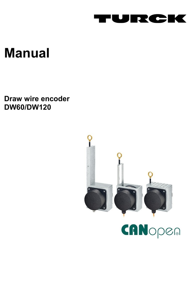
turck FOC1 Series User manual

Your Global Automation Partner
Instructions for Use
FOC1…
Media Converters FO

2Hans Turck GmbH & Co. KG | T +49 208 4952-0 | F +49 208 4952-264 | [email protected] | www.turck.com

V1.01 | 2021/12 3
Contents
1 About these instructions................................................................................................................ 5
1.1 Target groups................................................................................................................ 5
1.2 Explanation of symbols used ..................................................................................... 5
1.3 Other documents ......................................................................................................... 5
1.4 Feedback about these instructions........................................................................... 5
2 Notes on the product...................................................................................................................... 6
2.1 Product identification.................................................................................................. 6
2.2 Scope of delivery .......................................................................................................... 6
2.3 Turck service..................................................................................................................6
3 For your safety ................................................................................................................................. 7
3.1 Intended use.................................................................................................................. 7
3.2 General safety instructions......................................................................................... 7
3.3 Notes on Ex protection................................................................................................ 7
3.4 Requirements for ATEX and IECEx approval ........................................................... 7
4 Product description......................................................................................................................... 8
4.1 Device overview ........................................................................................................... 8
4.2 Properties and features............................................................................................... 9
4.3 Functions and operating modes .............................................................................11
5 Installing..........................................................................................................................................17
6 Connection......................................................................................................................................18
7 Commissioning ..............................................................................................................................25
8 Operation ........................................................................................................................................26
9 Setting .............................................................................................................................................27
9.1 Transfer rate (rotary switch).....................................................................................27
9.2 Bus parameters ...........................................................................................................28
10 Troubleshooting ............................................................................................................................34
11 Maintenance...................................................................................................................................35
12 Repair...............................................................................................................................................35
12.1 Returning devices.......................................................................................................35
13 Disposal ...........................................................................................................................................35
14 Technical data ................................................................................................................................36
14.1 Technical data – FOC1-…-2G ...................................................................................36
14.2 Technical data – FOC1-…-3G ...................................................................................37
15 Approvals and device markings .................................................................................................38
15.1 FOC1…-2G – approvals and device markings ......................................................38
15.2 FOC1…-3G – approvals and device markings ......................................................39
16 Turck subsidiaries - contact information ..................................................................................40
Contents
4Hans Turck GmbH & Co. KG | T +49 208 4952-0 | F +49 208 4952-264 | [email protected] | www.turck.com

V1.01 | 2021/12 5
1 About these instructions
These instructions for use describe the structure, functions and the use of the product and will
help you to operate the product as intended. Read these instructions carefully before using the
product. This is to avoid possible damage to persons, property or the device. Retain the instruc-
tions for future use during the service life of the product. If the product is passed on, pass on
these instructions as well.
1.1 Target groups
These instructions are aimed at qualified personnel with knowledge of explosion protection
(e.g. EN 60079-14 etc.) and must be carefully read by anyone mounting, commissioning, oper-
ating, maintaining, dismantling or disposing of the device.
1.2 Explanation of symbols used
The following symbols are used in these instructions:
DANGER
DANGER indicates a dangerous situation with high risk of death or severe injury if
not avoided.
WARNING
WARNING indicates a dangerous situation with medium risk of death or severe in-
jury if not avoided.
CAUTION
CAUTION indicates a dangerous situation of medium risk which may result in minor
or moderate injury if not avoided.
NOTICE
NOTICE indicates a situation which may lead to property damage if not avoided.
NOTE
NOTE indicates tips, recommendations and useful information on specific actions
and facts. The notes simplify your work and help you to avoid additional work.
uCALL TO ACTION
This symbol denotes actions that the user must carry out.
aRESULTS OF ACTION
This symbol denotes relevant results of actions.
1.3 Other documents
Besides this document the following material can be found on the Internet at www.turck.com:
nData sheet
nQuick Start Guide
nDeclarations of conformity (current versions)
nApprovals
1.4 Feedback about these instructions
We make every effort to ensure that these instructions are as informative and as clear as pos-
sible. If you have any suggestions for improving the design or if some information is missing in
the document, please send your suggestions to [email protected].

Notes on the Product
6Hans Turck GmbH & Co. KG | T +49 208 4952-0 | F +49 208 4952-264 | [email protected] | www.turck.com
2 Notes on the product
2.1 Product identification
These instructions apply to the following devices:
nFOC11-3G
nFOC11EX-2G
nFOC12-3G
nFOC12Ex-2G
2.2 Scope of delivery
The delivery consists of the following:
nFOC media converter
nTerminal block, 2-pin
nQuick Start Guide
2.3 Turck service
Turck supports you with your projects, from initial analysis to the commissioning of your applic-
ation. The Turck product database under www.turck.com contains software tools for program-
ming, configuration or commissioning, data sheets and CAD files in numerous export formats.
The contact details of Turck subsidiaries worldwide can be found on p. [}40].

V1.01 | 2021/12 7
3 For your safety
The product is designed according to state-of-the-art technology. However, residual risks still
exist. Observe the following warnings and safety notices to prevent damage to persons and
property. Turck accepts no liability for damage caused by failure to observe these warning and
safety notices.
3.1 Intended use
These devices are designed solely for use in industrial areas.
The FOC media converters of the FOC1… series convert electrical RS485 and RS485-IS signals
into optical signals and visa versa. The PROFIBUS-DP and Modbus bus signals (as well as other
serial data streams) can be transferred via the FO segments as isolated and interference-free
signals over distances of at least 2500 m. The FOC1...-2G media converters are provided with an
RS485-IS interface and are suitable for use in Zone 1. The FOC1...-3G media converters are
provided with a standard RS485 interface and are suitable for use in Zone 2. The intrinsically
safe FO interfaces (Ex op is) enable all media converters of the FOC series to be connected and
different FO network structures (point-to-point connections, ring topologies) to be set up.
The devices may only be used as described in these instructions. Any other use is not in accord-
ance with the intended use. Turck accepts no liability for any resulting damage.
3.2 General safety instructions
nThe device may only be assembled, installed, operated, parameterized and maintained by
professionally-trained personnel.
nThe device may only be used in accordance with applicable national and international regu-
lations, standards and laws.
nThe device meets the EMC requirements for industrial areas. When used in residential areas,
take measures to avoid radio interference.
nOnly combine devices for which the technical data is suitable for joint use.
3.3 Notes on Ex protection
nWhen using the device in Ex circuits, the user must also have an additional knowledge of ex-
plosion protection (IEC/ EN 60079-14 etc.).
nObserve national and international regulations for explosion protection.
nUse the device only within the permissible operating and ambient conditions (see approval
data and Ex approval specifications).
nOnly operate the device with an enclosed IP30 cover via the connection terminals.
nNever connect equipment to intrinsically safe circuits if this equipment was previously used
once in non-intrinsically safe circuits.
nCables and terminals with intrinsically safe circuits must be indicated (use light blue for
color-coding) and must be separated from non-intrinsically safe circuits or isolated accord-
ingly (IEC/EN 60079-14).
nCarry out a “Proof of intrinsic safety” (IEC/EN 60079-14).
nCombinations of FOC1…-2G and FOC1…-3G: Maintain a distance of 50 mm (thread dis-
tance) between the connection circuits of intrinsically safe and non-intrinsically safe circuits.
3.4 Requirements for ATEX and IECEx approval
nUse in Zones 1 and Zone 2: Install the device in a separately approved housing in accordance
with EN IEC 60079-0 with a protection type of at least IP54 in accordance with IEC/EN60529
and, if necessary, in compliance with IEC/EN 60079-7.
nUse in Zones 21 and Zone 22: Install the device in a separate housing in accordance with
ENIEC 60079-31.

Product description
8Hans Turck GmbH & Co. KG | T +49 208 4952-0 | F +49 208 4952-264 | [email protected] | www.turck.com
4 Product description
The FOC series consists of four FO media converters that differ in the RS485 interfaces, number
of FO ports provided and application areas:
nFOC11-3G: 1 × RS485 and 1 × FO op is, suitable for use in Zone 2
nFOC12-3G: 1 × RS485 and 2 × FO op is, suitable for use in Zone 2
nFOC11EX-2G: 1 × RS485-IS and 1 × FO op is, suitable for use in Zone 1
nFOC12EX- 2G: 1 × RS485-IS and 2 × FO op is, suitable for use in Zone 2
4.1 Device overview
mm [Inch]
91.6 [3.61]
65.1 [2.56] 73.5 [2.89]
10.3
[0.40]
105.4
[4.15]
8.9
[0.35]
Fig.1: FOC1… – Dimensions

V1.01 | 2021/12 9
2
1
4
5
6
7
8
3
9
10
Fig.2: FOC1… – Connections and operating elements
Position Description
1 Power supply connection
2 IP30 cover
3 Rotary switch: Baud rate/operating mode
4 FOC1…-3G: RS485 interface
FOC1…-2G: RS485-IS interface
5 RS485 shield: Screw head connected to M5 × 1 bolt (shield) – capacit-
ively with insulating washer, directly without insulating washer
6 FO interface, BFOC/2,5 (ST) connector
7 RS485 shield: M5 × 1-bolt (shield)
8 Alarm output
9 LED indicators
10 Housing potential: M5 × 1 bolt (case ground)
4.2 Properties and features
General features
nMedia converters for converting electrical RS485 and RS485-IS signals into intrinsically safe
optical signals and visa versa
nTransfer of PROFIBUS-DP telegrams, Modbus-RTU and other byte-oriented serial data tele-
grams
nFull galvanic isolation
nTransfer rates from 9.6 kbps…1.5 Mbps
nTransfer range of the FO segment: at least 2500 m with Multimodefiber OM1, at least 1500 m
with Multimodefiber OM2
nConnection of up to 31 bus stations (e.g. excom I/O systems) per segment
nRouting of the FO segment into Zone 1
nOptical interface with ST connectors for transmitter and receiver terminals
nAutomatic baud rate detection with PROFIBUS-DP
nRotary coding switches for setting the device functions
nAlarm output, connectable in series
nStatus LEDs (power supply, FO segment(s), RS485 and RS485-IS segment)
nAny combination possible with other FOC device variants

Product description
10 Hans Turck GmbH & Co. KG | T +49 208 4952-0 | F +49 208 4952-264 | [email protected] | www.turck.com
FOC11-3G – Properties
nInstallation in the safe area in Zone 2
n1 × RS485 interface
n1 × intrinsically safe FO interface (Ex op is)
n1 × electronic 24 V alarm contact
nApplications: FO point-to-point connection
FOC12-3G – Properties
nInstallation in the safe area in Zone 2
n1 × RS485 interface
n2 × intrinsically safe FO interface (Ex op is)
n1 × electronic 24 V alarm contact
nApplications: FO point-to-point connection, FO ring
FOC11EX-2G – Properties
nInstallation in the safe area as well as in Zone 1 and Zone 2
n1 × intrinsically safe RS485-IS interface
n1 × intrinsically safe FO interface (Ex op is)
n1 × NAMUR alarm output
nApplications: FO point-to-point connection
FOC12EX-2G – Properties
nInstallation in the safe area as well Zone 1 and Zone 2
n1 × intrinsically safe RS485-IS interface
n2 × intrinsically safe FO interface (Ex op is)
n1 × NAMUR alarm output
nApplications: FO point-to-point connection, FO ring

V1.01 | 2021/12 11
4.3 Functions and operating modes
Media converter
The media converter is supplied with 24 VDC in accordance with explosion protection type
Exe.
The RS485 interface enables up to 31 nodes (e.g. excom stations) to be connected. The FO me-
dia converter is a physical station and must be included as a bus device within a PROFIBUS seg-
ment.
The media converter regenerates the signal amplitude, edge steepness and bit width of
PROFIBUS telegrams. PROFIBUS-DP telegrams with a valid start delimiter are forwarded, and
faulty telegrams are discarded. The bit length and signal amplitude are conditioned (byte re-
fresh) with Modbus RTU and other byte-oriented serial data streams. Line faults (wire-break/
short-circuit) are not transmitted between segments. This ensures interference-free and inde-
pendent operation of all segments.
The RS485 connection is designed as a 9-pin SUB-D female connector. BFOC/2,5 (ST) male con-
nectors are available for connecting the FO cables. When using an OM1 62.5/125 μm multi-
modefiber cable the transfer range is at least 2500 m, with a 50/125 μm multimodefiber cable
the transfer range is at least 1500 m.
Transfer rates from 9.6 kbps to 1.5 Mbps are possible and are detected automatically in
PROFIBUS-DP mode. When using the Modus-RTU protocol, the transfer rate is set via a rotary
coding switch.
Diagnostic functions
Status LEDs (power supply, FO segment, RS485 segment and transfer rate detection in the
RS485 segment) and an alarm output are provided for diagnostic tasks. The alarm output is
connected via a two-pin male connector.
The FOC1…Ex-2G device variants are provided with a NAMUR alarm output. The alarm output
switches through during fault-free operation and switches off when a fault occurs. The alarm
output can be connected in series with the alarm output of another FOC…-2G and evaluated
via a NAMUR input module in accordance with IEC/EN 60947-5-6 (e.g. DM80Ex).
The FOC1…-3G device variants are provided with an electronic alarm contact. The alarm out-
put switches through during fault-free operation and switches off when a fault occurs. The
alarm contact can be connected in series with the alarm contact of another FOC…-3G and eval-
uated via a digital input module (e.g. DI80) or a NAMUR input (e.g. DM80). If installed in Zone 2,
the alarm contact must not be plugged in or unplugged under live conditions. The plug con-
nector is provided with locking screws.
The alarm output indicates the following faults:
nFault/malfunction inside the device (self diagnostic)
nOperating voltage too low/missing
nRS485: Communication error
nNo Idle signal/FO segment interrupted
nFO communication error
Setup of FO network structures
The FO media converters enable simple and complex FO network structures to be created. Both
individual stations as well as new segments with up to 31 stations can be connected to the
RS485 interface of the FOC media converters. The FO media converters are connected via the
RS485 interface with the field devices and via the FO interface with additional media convert-
ers. This makes it possible to change between RS485 and FO transmission within a system as re-
quired. The following applications can be implemented:
nFO point-to-point connection
nFO ring
nCombinations of FO ring and FO point-to-point connection

Product description
12 Hans Turck GmbH & Co. KG | T +49 208 4952-0 | F +49 208 4952-264 | [email protected] | www.turck.com
Single FO point-to-point connections
Depending on the application, a single point-to-point is implemented with the following
FOC11 media converters:
nThe FOC11-3G media converters are used to connect to the non-intrinsically safe RS485 in-
terface.
nThe FOC11EX-2G media converters are used to connect to the intrinsically safe RS485-IS in-
terface.
nThe FOC11 media converters are provided with an FO interface.
nFor the point-to-point connection: Set the coding switch of the devices to position 0 (only
applies to PROFIBUS-DP).
The following figure shows a single point-to-point connection in a PROFIBUS-DP network. Equi-
valent Modbus-RTU networks can be created. With Modbus RTU, the baud rate must be set
with the rotary coding switch (see chapter Setting/rotary coding switch):
FO is op
FO is op
PROFIBUS-DP
Nodes (max. 31)
PROFIBUS-DP
Nodes (max. 31)
FOC11-3G
TX RX
RS485
PORT
A
FOC11EX-2G
TX RX
RS485-IS
PORT
A
FOC11-3G
TX RX
RS485
PORT
A
FOC11-3G
TX RX
RS485
PORT
A
PROFIBUS-
DP Master
Fig.3: FOC media converters – single point-to-point connection

V1.01 | 2021/12 13
FO point-to-point connections – cascaded
Several FO media converters can be connected in series (cascaded) in order to lengthen FO seg-
ments. Depending on the application, a cascaded point-to-point connection is implemented
with the following FOC11 and FOC12 media converters:
nThe FOC11-3G and FOC12-3G media converters are used to connect to the non-intrinsically
safe RS485 interface.
nThe FOC11EX-2G and FOC12EX-2G media converters are used to connect to the intrinsically
safe RS485-IS interface.
nThe FOC11 media converters are provided with one FO interface and the FOC12 media con-
verters with two FO interfaces.
nFor the point-to-point connection: Set the coding switch of the devices to position 0 (only
applies to PROFIBUS-DP).
The following figures show two examples of cascaded point-to-point connections in a
PROFIBUS-DP network. Equivalent Modbus-RTU networks can be created. With Modbus RTU,
the baud rate must be set with the rotary coding switch (see chapter Setting/rotary coding
switch):
FO is op
PROFIBUS-
DP Master
PROFIBUS-DP
Nodes (max. 31)
PROFIBUS-DP
Nodes (max. 31)
PROFIBUS-DP
Nodes (max. 31)
FOC11-3G
TX RX
RS485
PORT
A
FOC12EX-2G
TX RX TX RX
PORT
B
RS485-IS
PORT
A
FOC11EX-2G
TX RX
RS485-IS
PORT
A
FOC12-3G
TX RX TX RX
PORT
B
RS485
PORT
A
Fig.4: FOC media converters – cascaded point-to-point connection

Product description
14 Hans Turck GmbH & Co. KG | T +49 208 4952-0 | F +49 208 4952-264 | [email protected] | www.turck.com
PROFIBUS-
DP Master
PROFIBUS-DP
Nodes (max. 31)
PROFIBUS-DP
Nodes (max. 31)
PROFIBUS-DP
Nodes (max. 31)
PROFIBUS-DP
Nodes (max. 31)
PROFIBUS-DP
Nodes (max. 31)
FOC12-3G
TX RX TX RX
PORT
B
RS485
PORT
A
FOC12EX-2G
TX RX TX RX
PORT
B
RS485-IS
PORT
A
FOC12EX-2G
TX RX TX RX
PORT
B
RS485-IS
PORT
A
FOC12-3G
TX RX TX RX
PORT
B
RS485
PORT
A
FOC12-3G
TX RX TX RX
PORT
B
RS485
PORT
A
FOC11-3G
TX RX
RS485
PORT
A
Fig.5: FOC media converters – cascaded point-to-point connection

V1.01 | 2021/12 15
FO ring ─ with PROFIBUS-DP
Depending on the application, an optical ring can be implemented in an FO network with
PROFIBUS-DP – using the following FOC12 media converters:
nThe FOC12-3G media converters are used to connect to the non-intrinsically safe RS485 in-
terface.
nThe FOC12EX-2G media converters are used to connect to the intrinsically safe RS485-IS in-
terface.
nThe FOC12 media converters are provided with two FO interfaces.
nUp to ten FOC media converters can be used for each FO ring.
nSetting the coding switch: first FOC12 media converter (ring master) to position 1, all other
media converters (ring slaves) to position 2.
The following figure shows a single FO ring with FOC12 media converters in a PROFIBUS-DP
network:
FO is op
FO ring primary: FO ring secondary:
PROFIBUS-
DP Master
PROFIBUS-DP
Nodes (max. 31)
PROFIBUS-DP
Nodes (max. 31)
PROFIBUS-DP
Nodes (max. 31)
PROFIBUS-DP
Nodes (max. 31)
FOC12-3G
TX RX TX RX
PORT
B
RS485
PORT
A
FOC12-3G
TX RX TX RX
PORT
B
RS485
PORT
A
FOC12EX-2G
TX RX TX RX
PORT
B
RS485-IS
PORT
A
FOC12EX-2G
TX RX TX RX
PORT
B
RS485-IS
PORT
A
FOC12-3G
TX RX TX RX
PORT
B
RS485
PORT
A
Fig.6: FOC media converters – FO ring with PROFIBUS-DP

Product description
16 Hans Turck GmbH & Co. KG | T +49 208 4952-0 | F +49 208 4952-264 | [email protected] | www.turck.com
Extended FO ring ─ with PROFIBUS-DP
The FOC12 FO media converters make it possible to create an optical ring in an FO network and
extend it via the RS485 interface using FOC11 and FOC12 media converters. The following fig-
ure shows an FO ring with a point-to-point connection in a PROFIBUS-DP network:
PROFIBUS-DP
Nodes (max. 31)
PROFIBUS-DP
Nodes (max. 31)
PROFIBUS-DP
Nodes (max. 31)
PROFIBUS-DP
Nodes (max. 31)
FOC12-3G
TX RX TX RX
PORT
B
RS485
PORT
A
FOC12-3G
TX RX TX RX
PORT
B
RS485
PORT
A
FOC12EX-2G
TX RX TX RX
PORT
B
RS485-IS
PORT
A
FOC12EX-2G
TX RX TX RX
PORT
B
RS485-IS
PORT
A
FOC11-3G
TX RX
RS485
PORT
A
FOC11EX-2G
TX RX
RS485-IS
PORT
A
FOC12-3G
TX RX TX RX
PORT
B
RS485
PORT
A
PROFIBUS-
DP Master
FO is op
FO ring primary: FO ring secondary:
Fig.7: FOC media converters – extended FO ring with PROFIBUS-DP
FO ring ─ with PROFIBUS-DP – operating principle
In normal operation all FOC12 media converters are connected via the FO ring. The physical
layer here consists of two optical rings: one primary ring and one secondary. Only the primary
optical ring is used for the data transfer, the secondary optical ring is only monitored (Idle sig-
nal). Up to ten FOC12 media converters can be used for each FO ring.
The FOC12 media converters detect the failure of an FO segment or another FOC12 media con-
verter in the FO ring and are able to compensate for the failure internally via the FO ring in or-
der to maintain communication. The FOC12 media converters can be replaced during opera-
tion without interrupting communication or added in order to extend the FO ring.

V1.01 | 2021/12 17
5 Installing
The FOC11-3G and FOC12-3G media converters can be installed as equipment in the safe area
and in Zones 2/22. For operation in Zone 2, install the devices in an approved Ex e housing in
accordance with EN 60079-0 with a protection type of at least IP54. Operation in Zone 22 re-
quires installation in a housing in accordance with EN 60079-31. The intrinsically safe optical
outputs can be routed into Zone 1/21.
DANGER
Potentially explosive atmosphere
Risk of explosion through spark ignition
Operation in FOC…-3G in Zone 2:
Only connect the device when it is in a de-energized state.
Installation in Zone 2: Do not connect or disconnect the alarm output under live
conditions.
Install the device in an Ex e housing in accordance with EN 60079-0 with a pro-
tection type of at least IP54.
When mounting the device, ensure that its permissible operating temperature is
not exceeded even in unfavorable ambient conditions.
When connecting different areas via the FO cable: Only use additional lens sys-
tems or light amplifiers if they have been approved for this purpose.
The FOC11EX- 2G and FOC12EX- FOC12Ex media converters can be installed as equipment in
the safe area and in Zones 1/21 or 2/22. For operation in Zone 1 or 2, install the devices in an
approved Ex e housing in accordance with EN 60079-0 with a protection type of at least IP54.
Operation in Zone 21 or 22 requires installation in a housing in accordance with EN 60079-31.
The intrinsically safe optical outputs can be routed into Zone 1/21.
DANGER
Potentially explosive atmosphere
Risk of explosion through spark ignition
Operation of FOC…-2G in Zone 1 or 2:
Only connect the device when it is in a de-energized state.
Install the device in an Ex e housing in accordance with EN 60079-0 with a pro-
tection type of at least IP54.
When mounting the device, ensure that its permissible operating temperature is
not exceeded even in unfavorable ambient conditions.
When connecting different areas via the FO cable: Only use additional lens sys-
tems or light amplifiers if they have been approved for this purpose.
Protect the mounting location from radiated heat, sudden temperature fluctuations,
dust, dirt, humidity and other ambient influences.
Install the device on a DIN rail (TH35).
Maintain a clearance of ≥ 5 mm from the side of the adjacent device.
Combinations of FOC1…-2G and FOC1…-3G: Maintain a distance of 50 mm (thread dis-
tance) between the connection circuits of intrinsically safe and non-intrinsically safe cir-
cuits.

Connection
18 Hans Turck GmbH & Co. KG | T +49 208 4952-0 | F +49 208 4952-264 | [email protected] | www.turck.com
6 Connection
Connections and operating elements
2
1
4
5
6
7
8
3
9
10
Fig.8: FOC1… – Connections and operating elements
Position Description
1 Power supply connection
2 IP30 cover
3 Rotary switch: Baud rate/operating mode
4 FOC1…-3G: RS485 interface
FOC1…-2G: RS485-IS interface
5 RS485 shield: Screw head connected to M5 × 1 bolt (shield) – capacit-
ively with insulating washer, directly without insulating washer
6 FO interface, BFOC/2,5 (ST) connector
7 RS485 shield: M5 × 1-bolt (shield)
8 Alarm output
9 LED indicators
10 Housing potential: M5 × 1 bolt (case ground)

V1.01 | 2021/12 19
Wiring diagrams
GN
Pwr
RS485
Port A
YE/RD
YE/RD
+
–
+
–
019
46
28
37
5
1
5
6
9
case ground
shield
a
RS485
Port A
TX
RX
24 VDC Pwr
GN
Pwr
RS485
Port A
YE/RD
YE/RD
Port B
YE/RD
+
–
019
46
28
37
5
1
5
6
9
+
–
case ground
shield
a
RS485
Port A
TX
TX
RX
RX
Port B
24 VDC Pwr
Fig.9: FOC11-3G – wiring diagram Fig.10: FOC12-3G – wiring diagram
GN
Pwr
RS485-IS
Port A
YE/RD
YE/RD
+
–
+
–
019
46
28
37
5
1
5
6
9
BN
BU
Port A
TX
RX
case ground
shield
a
RS485-IS
24 VDC Pwr
GN
Pwr
RS485-IS
Port A
YE/RD
YE/RD
Port B
YE/RD
+
–
+
–
019
46
28
37
5
1
5
6
9
BN
BU
case ground
shield
a
RS485-IS
Port A
TX
TX
RX
RX
Port B
24 VDC Pwr
Fig.11: FOC11EX-2G – wiring diagram Fig.12: FOC12EX-2G – wiring diagram

Connection
20 Hans Turck GmbH & Co. KG | T +49 208 4952-0 | F +49 208 4952-264 | [email protected] | www.turck.com
Connecting the power supply
DANGER
Potentially explosive atmosphere
Risk of explosion through spark ignition
Operation in Zone 1 or Zone 2: Only connect the device in a de-energized state
or if there is no potentially explosive atmosphere present.
The device is provided with a 2-pin Ex e terminal for connecting the power supply. The max-
imum terminal cross section is:
Single connection Multi-wire connection
Rigid 4 mm20.2…2.5 mm2
Flexible 2.5 mm20.2…1 mm2
Strip the connection cables for the power supply (9 mm).
Stranded wire cables: use ferrules.
„Slightly undo the fixing screws of the IP30 cover and push the cover back.
Connect the power supply to terminal 1 (+) and terminal 2 (-).
Tighten the terminals. The tightening torque is 0.4…0.5 Nm.
Pull the IP30 cover back to the front and fasten the fixing screws.
Connecting the equipotential bonding
Connect the M5 × 1 bolt (case ground) on the device to the equipotential bonding.
Connecting the RS485 shield
Depending on the expected interference and the installation, the user may choose between ca-
pacitive and direct grounding. T The shield is factory fitted with a capacitive connection to the
cable shield. his requires the insertion of an insulating washer between the screw head and the
cable shield.
Choosing direct grounding: unscrew the screw, remove the insulating washer and
retighten the screw.
If the shield is to be connected to the case ground housing potential: Connect the M5 × 1
bolt (shield) with the M5 × 1 bolt (case ground).
Table of contents
Other turck Media Converter manuals

turck
turck Ri-QR24 User manual

turck
turck Ri-QR24 User manual

turck
turck REM Series User manual

turck
turck QR24 User manual

turck
turck RI360P0 IOLX2 3GD Series User manual

turck
turck RES Series User manual

turck
turck REM Series User manual

turck
turck Ri-QR24 User manual

turck
turck RI360P0-EQR24M0-HESG25X3-H1181 User manual

turck
turck RI QR20 Series User manual