Brillion Compaction Commander 03 Series User manual

Page 1
OPERATOR’S MANUAL
C
ompaction
Commander
-03 MODELS:
Single Bar Frames
CCS3303 -5303
Double Bar Frames
CCD3303 -4303 -5243 -5303 -6243
-6303 -7303 -8303 -9243
BRILLION )$50(48,30(17
BRILLION, WISCONSIN 54110 9K308
604rev10-4-05
Brillion
Brillion
www.brillionfarmeq.com

Page 2
9K308
604 Page 1

Page 3
Introduction.......................................................................................................................................... 3
Location Reference ...................................................................................................................... 3
Parts Ordering ............................................................................................................................. 3
Safety Suggestions ............................................................................................................................ 4
Safety Warning Signs ..................................................................................................................... 5-7
Operating Instructions ....................................................................................................................... 8
Attaching Tractors With Category II Hitch.................................................................................... 8
Attaching Tractors With Category III Hitch................................................................................... 8
Level Adjustment.......................................................................................................................... 9
Turning ......................................................................................................................................... 9
Depth Control of Shanks............................................................................................................... 9
Depth Control of Coulter Assembly .............................................................................................. 9
Maintenance...................................................................................................................................... 10
Fasteners.................................................................................................................................... 10
Torque Chart............................................................................................................................... 10
Tires............................................................................................................................................ 11
Lubrication .................................................................................................................................. 11
Assembly Instructions ....................................................................................................................... 12
Basic Machine............................................................................................................................. 12
Stand Mount................................................................................................................................ 12
Couter Assembly ........................................................................................................................ 13
Shank Assembly......................................................................................................................... 14
Shank Mount Replacement....................................................................................................16
Gage Wheels ..............................................................................................................................17
Warning Lamp Assembly ............................................................................................................18
Model Configuration.................................................................................................................... 20
Row Marker Option......................................................................................................................28
Specifications ................................................................................................................................... 30
Model Designation.................................................................................................................... 30
Basic Machine Specifications .................................................................................................... 30
Contents
Contents
9K308
604rev10--05 Page 1

Page 4

Page 5
The Brillion Compaction Commander was
designed as a primary tillage tool imparting
minimum soil disturbance and soil eroison while
providing excellent break-up of compacted soil,
lifting it up enough to promote air and water
absorption.
To obtain maximum benefits, please study this
manual carefully before operating or starting as-
sembly of machine or optional equipment.
If items covered in this manual are not under-
stood, contact your local Brillion dealer.
This safety alert symbol
is used to call your
attention to instructions
concerning personal
safety. This symbol is found throughout this
manual and will be found on safety signs on
your machine. It points out important safety
precautions. It means “ATTENTION! BE
ALERT! YOUR SAFETY IS INVOLVED!”
Read the message that follows and be alert to
the possibility of personal injury or death.
SAFETY ALERT
Location Reference
Right hand, left hand and forward designations
are those related to the operator when sitting in
the operating position.
Be sure to read the warranty form which is
shipped with the machine. Return the proper
portion of the form for recording at the factory.
Parts Ordering
When ordering parts for this machine, include
the complete model number and serial number.
Refer to the name plate on the inside of the
frame’s right hand end plate. Please record
these numbers upon taking delivery of the unit.
Compaction Commander Model
Serial Number
Date Purchased
Figure 1
Nameplate
located here.
Introduction
Introduction
9K308
604 Page 3

Page 6
1. Do not stand between the tractor and
implement when attaching or detaching
implement unless both are not moving.
2. Before applying pressure to the hydraulic
system, be sure all connections are tight
and that hydraulic lines and hoses are not
damaged.
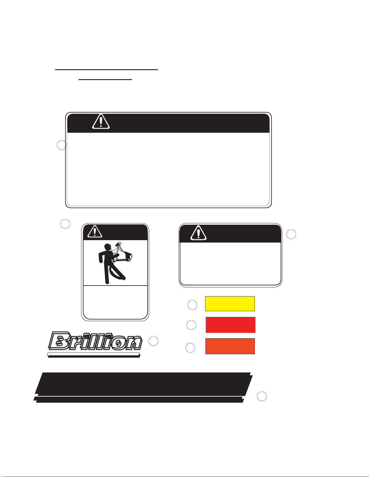
3. Escaping fluid under pressure can be
nearly invisible and have enough force to
penetrate the skin causing serious injury.
Use a piece of cardboard, rather than
hands, to search for suspected leaks. If
injured by fluid, see a doctor at once.
4. Do not make adjustments or lubricate
machine while it is in motion.
5. Do not allow anyone to ride on tractor or
machine.
7. Do not transport at speeds over 15 mph.
8. Avoid sudden stops or turns when trans-
porting because the weight of machine
may cause operator to lose control of
tractor. Use a tractor heavier than the
machine.
9. Use caution when towing behind articu-
lated steering tractors; fast or sharp turns
may cause the machine to shift sideways.
10. When transporting the machine on a road
or highway, use adequate warning sym
bols, reflectors, lights, and slow moving
vehicle signs as required.
11. Block machine so it will not roll when
unhitched from tractor.
12. Relieve pressure in hydraulic lines before
uncoupling hydraulic hoses from tractor.
On most tractors this can be done by
operating valves after engine is stopped.
13. Securely block machine when working on
or under it to prevent injury in case of
hydraulic failure or inadvertent lowering
by another person.
14. Lower machine to ground when not in use.
15. Springs of shank assemblies are under
load Do not remove bolts as improper
removal of spring assembly bolts could
result in serious injury.
Federal law requires that you explain the safety and operating instructions
furnishedwiththismachinetoallemployeesbeforetheyareallowedtooper-
atethe machine. These mustberepeated totheemployeesat thebeginning
of each season. Be sure to observe and follow the instructions for the safety
of anyone operating or near the machine.
Investigationhasshownthatnearlyone-thirdofallfarmaccidentsarecaused
by careless use of machinery. You can do your part in improving safety by
observing the following suggestions. Insist that all people working with you
or for you abide by them.
Safety Suggestions
Safety Suggestions
9K308
604 Page 4

Page 7
Safety Signs
Safety Signs
There are three levels of hazard intensity that ap-
pearwiththesafetyalertsymbolonsafetydecals:
DANGER, WARNING, and CAUTION. The level
of hazard intensity is determined by the following
definitions:
DANGER - Immediate hazards which
WILL result in death or serious
personal injury.
WARNING - Hazards or unsafe practices
which COULD result in death or
serious personal injury.
CAUTION - Indicates potentially hazardous
situations, or directs attention to
unsafe practices which could
result in minor or moderate injury.
•Examine safety decals and be sure you
have the correct safety decals for the
machine.
• Order replacement decals through your
BRILLION dealer.
•Keep these signs clean so they can be
observed readily. It is important to keep
these decals cleaned more frequently
than the machine. Wash with soap and
water or cleaning solution as required.
• Replace decals that become damaged or
lost. Also be sure that any new machine
components installed during repair
include decals which are assigned to
them by the manufacturer.
• When applying decals to the machine,
be sure to clean the surface to remove
any dirt or residue. Where possible, sign
placement should protect the sign from
abrasion, damage, or obstruction from
mud, dirty oil, etc.
• Decals for the Zone Commander, as well
as their locations on the machine, are
pictured on the following two pages.
9K308
604 Page 5

Page 8
Compaction Commander
Safety Signs:
1
1. 8J310 - Caution List
2. 2K762 - Spring Under Load
3. 9K829 - Deep Till Caution
4. 2J431 - Amber Reflective
5. 2J430 - Red Reflective
6. 8K597 - Red-Orange Reflective
7. 4K103 - Brillion
8. 4K067 - Compaction Commander
5
7
2
DEEP TILL OPERATION CAN DAMAGE
UNDERGROUND UTILITIES CAUSING
DANGEROUS CONDITIONS AND
DISRUPTING SERVICES. DETERMINE
THE DEPTH AND LOCATION OF BURIED
CABLES, PIPE LINES, AND DRAIN TILES
BEFORE OPERATION.
CAUTION
4
6
3
8J310
CAUTION
1. DO NOT LUBRICATE, ADJUST OR REPAIR WHEN MACHINE IS IN MOTION.
2. DO NOT TOW OR TRANSPORT FASTER THAN 15 MILES PER HOUR.
3. DO NOT RIDE ORALLOW OTHERS TO RIDE ON THE MACHINE.
4. BLOCK UPALL HYDRAULICALLY OR MECHANICALLY RAISED COMPONENTS TO
PREVENT UNINTENDED LOWERING OR LOWER THE MACHINE TO THE GROUND TO
MAKEADJUSTMENT OR REPAIRS WHEN NOT IN USE.
5. KEEPALL PERSONSAWAY FROM MACHINE DURING HITCHING AND OPERATING.
6. SLOW DOWN BEFORE MAKING SHARP TURNS OR USING THE BRAKES.
DRIVE SLOWLY OVER ROUGH GROUND, SIDE HILLS, AND AROUND CURVES TOAVOID TIPPING.
7. COMPLY WITH ALL LAWS WHEN TRANSPORTING THE MACHINE ON PUBLIC ROADWAYS.
8. INSTRUCTALL OPERATORS IN THE SAFE OPERATION OF THE MACHINE.
REVIEW THE OPERATOR’S MANUAL FOR CORRECT PROCEDURES.
9. BLOCK IMPLEMENT TO PREVENT MOVEMENT WHEN UNHITCHED FROM TRACTOR.
10. KEEPALL GUARDSAND SHIELDS IN PLACE WHILE MACHINE OR PARTS ARE IN MOTION.
Brillion
Brillion
Compaction
Commander
8
9K308
604 Page 6
WARNING
SPRING UNDER LOAD
DO NOT DISASSEMBLE WITHOUT USE OF
SERVICE TOOLAND FOLLOWING PROCEDURE
OUTLINED IN OPERATOR’S MANUAL.
SPRING IS LOADED AND IMPROPER
REMOVAL OF BOLTS COULD RESULT
IN SERIOUS INJURY. 2K762

Page 9
CAUTION
DEEP TILL OPERATION CAN DAMAGE
UNDERGROUND UTILITIES CAUSING
DANGEROUS CONDITIONS AND
DISRUPTING SERVICES. DETERMINE
THE DEPTH AND LOCATION OF BURIED
CABLES, PIPE LINES, AND DRAIN
TILES BEFORE OPERATION.
8K829
Brillion
Brillion
On Rear Frame
Between Shanks
5
1. DO NOT LUBRICATE, ADJUST OR REPAIR WHEN MACHINE IS IN MOTION.
2. DO NOT TOW ORTRANSPORT FASTER THAN 15 MILES PER HOUR.
3. DO NOT RIDE ORALLOW OTHERS TO RIDE ON THE MACHINE.
4. BLOCK UP ALL HYDRAULICALLY OR MECHANICALLYRAISED COMPONENTS TO
PREVENT UNINTENDED LOWERING OR LOWER THE MACHINE TO THE GROUND TO
MAKE ADJUSTMENT OR REPAIRS WHEN NOT IN USE.
5. KEEPALL PERSONSAWAY FROM MACHINE DURING HITCHINGAND OPERATING.
6. SLOW DOWN BEFORE MAKING SHARP TURNS OR USING THE BRAKES.
DRIVE SLOWLY OVER ROUGH GROUND, SIDE HILLS,ANDAROUND CURVES TOAVOID ......
TIPPING.
7. COMPLY WITHALL LAWS WHEN TRANSPORTING THE MACHINE ON PUBLIC ROADWAYS.
8. INSTRUCTALL OPERATORS IN THE SAFE OPERATION OF THE MACHINE.
REVIEW THE OPERATOR’S MANUALFOR CORRECT PROCEDURES.
9. BLOCK IMPLEMENT TO PREVENTMOVEMENT WHEN UNHITCHED FROM TRACTOR.
10. KEEPALL GUARDSAND SHIELDS IN PLACE WHILE MACHINE OR PARTS ARE IN MOTION.
CAUTION
C
ompaction
C
ommander
7
8
4
3
4
2 1
9K308
604 Page 7
SPRING UNDER LOAD
DO NOT DISASSEMBLE WITHOUT USE OF
SERVICE TOOL& FOLLOWING PROCEDURE
OUTLINED IN OPERATOR’S MANUAL.
SPRING IS LOADED AND IMPROPER
REMOVAL OF BOLTS COULD RESULT
IN SERIOUS INJURY.
2K762
WARNING

Page 10
Category II Hitch
Category III Hitch
Install 1 1/8” diamter lower hitch pins with pin
stop toward inside of machine. Secure with 1/2”
capscrew and lock nut.
The 1-1/4” O.D. x 1-15/16” Long sleeve may be
used on smaller framed machines.
Be sure all hitch points seat properly.
Watch for possible interference between
the tool bar and tractor linkages when rais-
ing for the first time.
Install1-7/16” x 6”long lowerhitch pins asshown
with pin stop toward inside of machine.
Secure with 1/2-13 NC x 3” capscrews and lock
nuts.
ATTACHING TO TRACTOR
Operation
Operation
HHCS,
1/2-13 NC X 3”
LOCK NUT,
1/2-13 NC
PIN ASSEMBLY,
1-1/8” DIA.
SLEEVE,
1-5/32 I.D. x 1-7/16” O.D.
x 2-7/8” LONG
HHCS,
1/2-13 NC X 3”
LOCK NUT,
1/2-13 NC
PIN ASSEMBLY,
1-7/16” DIA.
Figure 3a
Figure 3b
9K308
604 Page 8
SLEEVE,
1-1/32 I.D. x 1-7/16” O.D.
x 2-7/8” LONG
HHCS,
3/8-16 NC X 2 1/2”
LOCK NUT,
3/8-16 NC
PIN ASSEMBLY, 1” DIA.
HHCS,
3/8-16 NC X 2 1/2”
LOCK NUT,
3/8-16 NC
PIN ASSEMBLY, 1-1/4” DIA.

Page 11
LEVEL ADJUSTMENT
Adjust the length of the top link so that the
machine is parallel (front to rear) to the ground
surface when operating at the desired depth.
TURNING
The machine should always be raised com-
pletely out of the ground when turning. This
will relieve stress on the shanks, mounting
hardware, and machine frame.
DEPTH CONTROL of SHANKS
Adjust the height of the manual
gauge wheel by removing the
bolts and sliding the gauge wheel
arm to the desired position within
the mount. Replace the bolts and
tighten before operating. See
Figure 4.
Manual Gauge Wheel
DEPTH CONTROL of
COULTER ASSEMBLY
After the desired depth of the shanks have
been set, changes to the working depth of the
coulter blades can be made. Simply lower the
assembly by loosening the locking nuts and set
screws which hold the shaft. Adjust to desired
depth, make sure that the coulter stop is facing
forward to allow the coulter arm to swing side to
side. See Figure 7.
Tighten the set screws and the locking nuts.
LOCKWASHER, 5/8”
LOCK NUT, 5/8-11NC
HHCS, 5/8-11
NC X 9 1/2” MOUNT
GAGE WHEEL
ADJUST HEIGHT
LOCK NUT
5/8-11
ADJUST HEIGHT
SET SCREWS
COULTER ASSEMBLY
Figure 4a Figure 4b
9K308
604 Page 9

Page 12
Fasteners
Before operating your Brillion Zone
Commander, check all hardware
for tightness. Use the Tightening Torque
Chart reproduced below as a guide.
After a few hours use, check entire machine
and tighten any loose nuts or bolts. Daily or
periodic checks should be made thereafter.
1/4-20 5 8 12 5/7 7/10
THREAD
SIZE
BOLT / NUT TIGHTENING TORQUES
BOLT GRADE PLATED, STOVER
LOCK NUTS
grade 2 grade 5 grade 8 grade B grade C
min / max min / max
5/16-18 11 17 24 10/12 11/16
3/8-16 20 30 45 15/20 20/28
7/16-14 30 50 70 23/32 31/43
1/2-13 50 75 105 37/50 45/62
9/16-12 70 110 155 50/70 70/95
5/8-11 100 150 210 70/95 90/122
3/4-10 170 270 375 125/165 155/210
7/8-9 165 430 610 185/250 225/312
1-8 250 645 910 275/375 360/462
1 1/8 - 7 355 795 1290
1 1/4 - 7 500 1120 1820
1 3/8 - 6 745 1670 2710
1 1/2 - 6 870 1950 3160
VALUES GIVEN ARE IN FOOT-POUNDS
FOR FINE THREAD SERIES, MULTIPLY VALUES BY 1.1
USE GRADE B LOCK NUTS WITH GRADE 2 AND GRADE 5BOLTS ONLY.
USE GRADE CLOCK NUTS WITH GRADE 8 BOLTS ONLY.
3/4-16 375 155/210
Maintenance
Maintenance
9K308
604 Page 10

Page 13
NOTE: USE OF SMALLER OR
LIGHTER TIRES WILL CAUSE
PREMATURE TIRE FAILURE
AND MAY CAUSE AN ACCIDENT.
Tires
The wheels furnished with
the ZONE COMMANDER are
designed for use with 9.5L-15 or 11L-15
implement tires. These tires must be
inflated to 30 psi.
Lubrication
Wheel bearings should be
repacked annually.
Coulter assemblies should be
greased after every 20 hours of
use and greased if the machine
is not to be used for some time.
20
HRS.
20
HRS.
Figure 5a
Figure 5b
Repack
Annually.
9K308
604 Page 11

Page 14
ASSEMBLY INSTRUCTIONS
Additional parts identification and location can
be obtained from reviewing parts catalog.
To assemble machine, select a smooth level
area that can be reached by a hoist or lift truck.
NOTE:
6-shank frame unit is shown in figures.
The smaller and larger frame units
are similar but reference to figures may not
always be an exact representation.
STAND
STAND
MOUNT
CLEVIS PIN, 3/4” x 4”
HAIRPIN COTTER
HHCS, 5/8-11NC x 1-3/4”
LOCK NUT, 5/8-11 NC
COTTER PIN,
3/16” x 3”
FRAME
Figure 6
NOTE: Supports not shown. Stands
may not be shown in following
figures in order to make other
parts more identifiable.
Note: Mount stands as far toward
the outsides of the machine
as possible.
Basic Machine
1. Place frame on supports (approx. 38”
high). Be sure supports will hold 1500#
each.
DO NOT WORK UNDER
MACHINE UNLESS IT IS
BLOCKED UP SECURELY.
2. If your model has frame extensions,
mount them to the frame ends with 5/8”
capscrewss and lock nuts, and mount the
stand mounts to the front of frame with
3/4” U-bolts, lock washers, and nuts. See
Figure 6. Install the stand into the stand
mount and fasten with 3/4” dia. x 4” clevis
pin and hairpin cotter.
Assemblyy
Assembly
STAND
NUT, 3/4-10NC
LOCK WASHER, 3/4”
U-BOLT, 3/4”
FRAME EXTENSION
9K308
604 Page 12

Page 15
Figure 7
See Figure 15 for an example of a typical
machine configuration. (CCD6303) Refer
to the diagrams in FIGURES 16a-j for more
specific machine layouts.
Offset Bracket (used in models where
normal placement interferes with mast).
U-BOLT, 3/4”
LOCK WASHER, 3/4”
NUT, 3/4-10 NC
SET SCREW,
5/8-11 x 2” (SQ. HD)
NUT, 5/8-11 NC
COLLAR
3. Coulter Assemblies
Attach 6K678 mounting brackets to the
front tube with 3/4” 7 x 5 U-bolts. Attach
coulter assemblies to each mounting
bracket. Slide the shank into the tube
on the bracket and hold in place with 3 set
screws and nuts as shown in figure 7.
REAR OF
MACHINE
MOUNTING
BRACKET
COLLAR
(2) SET SCREWS,
5/8-11 x 2” (SQ. HD)
(2) NUTS, 5/8-11 NC
9K308
604 Page 13

Page 16
4. Shank Assemblies
PIN ASSEMBLY
HHCS,
5/8-11 NC x 4”
(2) 5/8” FLAT WASHERS
HHCS,
7/8-9 NC x 4 1/2”
CAPSCREW,
7/8-9 NC x 7 1/2”
CAPSCREW,
5/8 NC x 3 1/4”
5/8” lOCK WASHERS
HEX NUTS, 5/8-11 NC
Lock Nut,
7/8-9 NC
Figure 8
END VIEW OF ROLL
PINS OPEN EDGES
MUST NOT BE
ON SAME SIDE.
PARABOLIC
SHANK LEG
CARRIAGE BOLT, 3/4 X4”
3/4-10 NC Lock Nut,
V-WEARSTRIP
V-SHAPED CAST
STEEL POINT
(1) - 5/16” X 2” ROLL PIN
assemble inside
(1) - 1/2” X 2” ROLL PIN
2 ROLL PINS:
9K308
604 Page 14
HHCS, 1/2” x 2 1/2”
LOCK NUT, 1/2-13NC

Page 17
-Assemble shank mount with front shank
clamp to rear tube of machine directly
behind each coulter assembly.
- Attach as shown using (2) 7/8-9 NC x 4 1/2”
capscrews and locknuts over the top of the
frame and (2) 7/8-9 NC x 7 1/2” ” gr. 5
capscrews and locknuts underneath.
•Torque shank mounting clamp bolts to
200 ft. lbs.
FRONT
CLAMP
REAR OF
MACHINE
CAPSCREW,
7/8-9 NC x 4 1/2”
LOCK NUT,
7/8-9 NC
Figure 9
CAPSCREW,
7/8-9 NC x 7 1/2”
9K308
604 Page 15

Page 18
Service of Preloaded Shank Assembly
SPRING IS UNDER LOAD
Do not disassemble without use of service tool and following the procedure.
Spring is loaded and improper removal of bolts could result in serious injury.
Refer to Repair Parts Catalog for additional help in identifying parts of shank
assembly and service kit.
SERVICE INSTRUCTIONS
1. Install service tool as shown in Diagram A.
Plate slides through the back of the rear
bracket and the lug is pinned to the hole in
front bracket casting. Secure pins with
hairpin cotters.
2. Slightly loosen both bottom bolts of rear
bracket.
3. Retract the ratchet assembly of the service
tool to transfer the force of the spring to
the service tool. Continue until the bolt
to be removed, as shown in Diagram B, is loose
and can be removed.
4. Remove bolt shown in Diagram B and extend the
ratchet assembly of the service tool until
the spring is relaxed.
5. Service parts as needed.
PRELOAD INSTRUCTIONS
1. Install service tool as shown in Diagram B.
Plate slides through the back of the rear
bracket. Pin the lug to the hole in the
front bracket casting and secure pins with
hairpin cotters.
2. Retract the ratchet assembly of the service
tool to pivot the rear bracket about the pivot
bolt shown in Diagram B. Retract the assembly
until the 21 1/16” dimension between spring
mount centers is achieved.
3. Tighten carriage bolt firmly against shank and lock
in place with 3/4” hex nut.
Tighten remaining bolts at this time.
4. Install the bolt that had been removed for service.
5. Extend the ratchet assembly of the service tool
until it is relaxed.
Remove the service tool.
BOLT TO BE REMOVED
PIVOT BOLT
(5/8” X 4” CAPSCREW,
FLAT WASHERS, & LOCK NUT)
DIAGRAM B
21 1/16”
SERVICE TOOL
REAR BRACKET
DIAGRAM A
5/8” x 3 1/4” CAPSCREW,
LOCKWASHER, &HEX NUT
3/4” SET SCREW
(or Carriiage Bolt)
& 3/4” HEX NUT
9K308
604 Page 16

Page 19
Figure 10
CAPSCREW,
5/8-11 NC x 9 1/2”
LOCKWASHER, 5/8”
NUT, 5/8-11 NC
MOUNTING PLATE
REAR OF
MACHINE
5. Gage Wheels
Mount the gage wheels to the rear frame
tube of the machine. Mount one gage
wheel and bracket near the left end of the
frame and one near the right end. Their
exact location on the frame is at the discretion
of the owner/operator.
9K308
604 Page 17
CAPSCREW,
5/8-11 NC x 4”

Page 20
1. Assemble the light bar to the angles on their
supportswith 3/8-16U-bolts,and thesupports tothe
rear tube of the frame with 5/8-11NC U-bolts and
locknuts. Theside ofthelightbar withthered decals
goes toward the rear, and the side with amber
only toward the front of the machine.
WARNING LAMP ASSEMBLY
2. Attach an amber lamp to the two plates at
thefar-left and -rightoutside positions onthe light
bar and a red lamp to the two plates toward the
center, with the red-lighted side facing the rear of
themachine. Use (4)1/4-20 NCx 1/4”capscrews
and flanged lock nuts for each lamp.
Assemble Wiring:
4. Connect “wishbone” wiring harness ends to
connectors on lamp assemblies. Run wishbone
harness wires along the light bar to center of ma-
chine.
5. At center of machine,
assemble the connector
to the connector of the light module.
3. Fasten the light module to the front side of the
light bar at the center just under the SMVbracket.
6. Assemble the connector of the light module
to the connector of the straight harness and run it
down the center of the machine and to the front of
the drawbar along the side of the hydraulic hoses.
Light Module
REAR
Wishbone
Harness
Straight
Harness
Red Lamp
3/8-16 U-bolts &
Lock Nuts
5/8-11 U-bolts &
Lock Nuts REAR
Amber Lamp
(4) 1/4-20 NC x 1-1/4” capscrews &
flanged lock nuts for each lamp.
Figure11
Figure 12
9K308
604 Page 18
This manual suits for next models
9
Table of contents
Other Brillion Farm Equipment manuals

Brillion
Brillion SCP-23 Instruction Manual

Brillion
Brillion SOIL BUILDER II User manual

Brillion
Brillion CPP-7 Series User manual

Brillion
Brillion Zone Commander ZSF-8301 User manual

Brillion
Brillion Landcommander II LCS3302 User manual

Brillion
Brillion Zone Commander ZM3302 User manual

Brillion
Brillion HFC Field Commander Series User manual

Brillion
Brillion Zone Commander ZS33O1 User manual

Brillion
Brillion PPF Series Use and care manual

Brillion
Brillion Land Commander III LCS5303-4 User manual