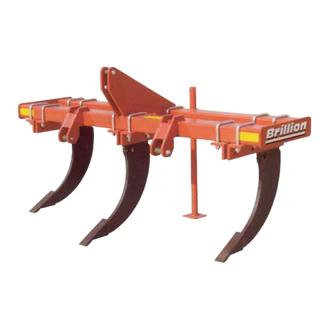
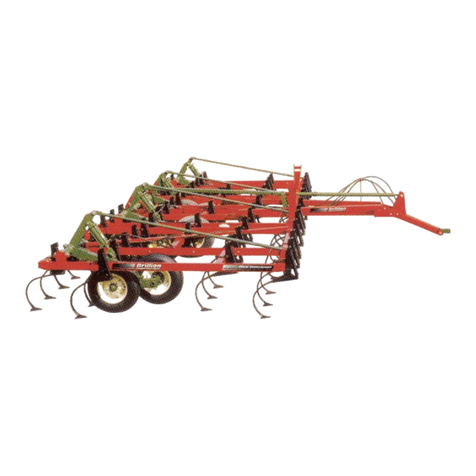
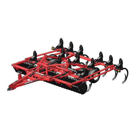
Brillion Zone Commander ZSF-8301 User manual

OPERATOR’S MANUAL
ASSEMBLY INSTRUCTIONS
BRILLION )$50(48,30(17
BRILLION, WISCONSIN 54110 8K974
1103rev3-28-08
DRAWBAR Pull Type
Zone Commander
R
Brillion
Brillion
MODELS:
ZSF -8301;-8302 -10301;-10302 -12301;-12302
ZSF -12302-6 (Hybrid)
ZRF -8301;-8302
ZST -8301;-8302 -6301;-6302
ZRT -6301;-6302 Note: All -01 models have been
updated to -02 specifications
www.brillionfarmeq.com


8K9741103rev10-15-07 Page 1
Introduction.......................................................................................................................................... 3
Location Reference ...................................................................................................................... 3
Parts Ordering .............................................................................................................................. 3
Safety Suggestions ............................................................................................................................ 4
Safety Warning Signs ................................................................................................................... 5-7b
Safety Chain.........................................................................................................................................8
Operating Instructions ....................................................................................................................... 9
Level Adjustment.......................................................................................................................... 9
Turning ......................................................................................................................................... 9
Depth Control of Shanks............................................................................................................... 9
Depth Control of Coulter Assembly............................................................................................... 9
Maintenance................................................................................................................................. 10-11
Fasteners.................................................................................................................................... 10
Torque Chart............................................................................................................................... 10
Tires............................................................................................................................................ 11
Lubrication .................................................................................................................................. 11
Assembly Instructions (excluding Hybrid) ................................................................................... 12-35
Frame & Cylinder Anchors.......................................................................................................... 12
Wheels & Wheel Cylinders ................................................................................................... 13, 14
Hinge Anchor/Wings ..............................................................................................................15, 16
Drawbar .......................................................................................................................................17
Couter Assembly................................................................................................................... 18, 19
Shank Assembly ......................................................................................................................... 20
Auto Reset......................................................................................................................... 20, 21
Shear Bolt.............................................................................................................................. 21a
Shank Mount & Leg Replacement...............................................................................................22
Shear Bolt Replacement..............................................................................................................23
Hydraulics...........................................................................................................................................24
Routing & Hose Clamps...............................................................................................................24
Wing Lift Hydraulics.....................................................................................................................26
Wheel Hydraulics.........................................................................................................................28
Warning Lamp Assembly ............................................................................................................30
ASSEMBLY & HYDRAULICS OF HYBRID MODEL................................................................ 31a-31j
Model Configuration .................................................................................................................... 32-35
Options......................................................................................................................................... 36-41
Support Arm Kits..........................................................................................................................36
Coulter & Disc Kits.................................................................................................................36, 37
Basket Kit; Wheel Kits............................................................................................................38, 39
Row Markers (Unwinged Models)..............................................................................................39a
Wear Strip & Points .................................................................................................................... 40
Cover Board Kit .......................................................................................................................... 40
Rigid Rear Hitch...........................................................................................................................41
Specifications ....................................................................................................................................42
Model Designation..................................................................................................................... 42
Basic Machine Specifications .....................................................................................................42
Contents

8K974Page 2

8K9741103rev11-15-07 Page 3
The Brillion Zone Commander was designed
as a primary tillage tool imparting minimum soil
disturbance and soil eroison while providing
excellent break-up of compacted soil, lifting it
up enough to promote air and water absorp-
tion.
To obtain maximum benefits, please study this
manual carefully before operating or starting
assembly of machine or optional equipment.
If items covered in this manual are not under-
stood, contact your local Brillion dealer
This safety alert symbol
is used to call your
attention to instructions
concerning personal
safety. This symbol is found throughout this
manual and will be found on safety signs on
your machine. It points out important safety
precautions. It means “ATTENTION! BE
ALERT! YOUR SAFETY IS INVOLVED!”
Read the message that follows and be alert to
the possibility of personal injury or death.
SAFETY ALERT
Parts Ordering
When ordering parts for this machine, include
the complete model number and serial num-
ber. Refer to the name plate on the left hand
side of the hitch plate. Please record these
numbers upon taking delivery of the unit.
INTRODUCTION
Location Reference
Right hand, left hand and forward designations
are those related to the operator when sitting
in the operating position.
Be sure to read the warranty form which is
shipped with the machine. Return the proper
portion of the form for recording at the factory.
Figure 1
Zone Commander Model
Serial Number
Date Purchased
Name Plate
Located Here.
Drawbar
Mast
Introduction
Introduction

8K9741103rev4-6-04 Page 4
1. Do not stand between the tractor and
implement when attaching or detaching
implement unless both are not moving.
2. Before applying pressure to the hydraulic
system, be sure all connections are tight
and that hydraulic lines and hoses are not
damaged.
3. Escaping fluid under pressure can be
nearly invisible and have enough force to
penetrate the skin causing serious injury.
Use a piece of cardboard, rather than
hands, to search for suspected leaks. If
injured by fluid, see a doctor at once.
4. Do not make adjustments or lubricate
machine while it is in motion.
5. Do not allow anyone to ride on tractor or
machine.
7. Do not transport at speeds over 15 mph.
8. Avoid sudden stops or turns when trans-
porting because the weight of machine
may cause operator to lose control of
tractor. Use a tractor heavier than the
machine.
9. Use caution when towing behind articu-
lated steering tractors; fast or sharp turns
may cause the machine to shift sideways.
10. When transporting the machine on a road
or highway, use adequate warning
symbols,
reflectors, lights, and slow moving
vehicle signs as required.
11. Block machine so it will not roll when
unhitched from tractor.
12. Relieve pressure in hydraulic lines before
uncoupling hydraulic hoses from tractor.
On most tractors this can be done by
operating valves after engine is stopped.
13. Securely block machine when working on
or under it to prevent injury in case of
hydraulic failure or inadvertent lowering
by another person.
14.
Lower machine to ground when not in use.
15. Springs of shank assemblies are under
load Do not remove bolts as improper
removal of spring assembly bolts could
result in serious injury.
Federal law requires that you explain the safety and operating instructions
furnishedwiththismachinetoallemployees before they are allowed tooper-
atethemachine. These mustberepeatedto theemployeesatthe beginning
of each season. Be sure to observe and follow the instructions for the safety
of anyone operating or near the machine.
Safety Suggestions
Safety Suggestions

8K9741103rev4-6-04 Page 5
There are three levels of hazard intensity that
appear with the safety alert symbol on safety
decals: DANGER, WARNING, and CAUTION.
The level of hazard intensity is determined by
the following definitions:
DANGER - Immediate hazards which
WILL result in death or serious
personal injury.
WARNING - Hazards or unsafe practices
which COULD result in death or
serious personal injury.
CAUTION - Indicates potentially hazardous
situations, or directs attention to
unsafe practices which could
result in minor or moderate injury.
•Examine safety decals and be sure you
have the correct safety decals for the
machine.
• Order replacement decals through your
BRILLION dealer.
•Keep these signs clean so they can be
observed readily. It is important to keep
these decals cleaned more frequently
than the machine. Wash with soap and
water or cleaning solution as required.
• Replace decals that become damaged or
lost. Also be sure that any new machine
components installed during repair
include decals which are assigned to
them by the manufacturer.
• When applying decals to the machine,
be sure to clean the surface to remove
any dirt or residue. Where possible, sign
placement should protect the sign from
abrasion, damage, or obstruction from
mud, dirty oil, etc.
• Decals for the Zone Commander are
pictured below. Their locations on
the machine are shown on the following
page.
Safety Signs
Safety Signs

8K9741103rev4-6-04 Page 6
1. 8J310 - Caution List
2. 3K706 - Hydraulic Leak Hazard
3. 2J431 - Amber Reflective
4. 2J430 - Red Reflective
5. 8K597 - Red-Orange Decal
6. 9J629 - Watch for Electrical Wires
7. 5J333 - Drawbar-Light with Attachments
8. 3J678 - Bleed Air from Cylinders
9. 3J675 - Falling Wings
10. 6K883 - Shank Under Load
11. 8K829 - Deep Till Caution
12. 6K800 - Zone Commander
13. 4K103 - Brillion
13a.
4K036 - Brillion
14. 9K129 - Shear Bolt decal
WARNING
SHANK IS ALWAYS UNDER LOAD
DO NOT USE HANDS OR FEET
TO DISLODGE ANY OBSTRUCTION
HOLDING THE SHANK IN THE
TRIPPED POSITION
SHANK IS SPRING LOADED
AND SERIOUS INJURY COULD
RESULT AS SHANK RESETS
6K883
3J675
FALLING WINGS CAN CAUSE INJURY
OR DEATH. STAND CLEAR WHEN WINGS
ARE BEING RAISED OR LOWERED.
DANGER
IMPORTANT
USE GRADE 2 BOLT
AT THIS LOCATION
9K129
DANGER
HARROWS OR OTHER DEVICES MOUNTED ON THE REAR OF
THIS MACHINE WILL USUALLY MAKE IT DRAWBAR-LIGHT. TO
AVOID PERSONAL INJURY FROM MACHINE TIPPING REARWARD,
ALWAYS
LOWER MACHINE TO GROUND BEFORE DISCONNECTING
TRACTOR.
SEE OPERATOR’S MANUAL FOR DETAILS.
5J333
DEEP TILL OPERATION CAN DAMAGE
UNDERGROUND UTILITIES CAUSING
DANGEROUS CONDITIONS AND
DISRUPTING SERVICES. DETERMINE
THE DEPTH AND LOCATION OF BUR-
IED CABLES, PIPE LINES, AND DRAIN
TILES BEFORE OPERATION.
CAUTION
8J310
CAUTION
1. DO NOT LUBRICATE, ADJUST OR REPAIR WHEN MACHINE IS IN MOTION.
2. DO NOT TOW OR TRANSPORT FASTER THAN 15 MILES PER HOUR.
3. DO NOT RIDE ORALLOW OTHERS TO RIDE ON THE MACHINE.
4. BLOCK UPALL HYDRAULICALLY OR MECHANICALLY RAISED COMPONENTS TO
PREVENT UNINTENDED LOWERING OR LOWER THE MACHINE TO THE GROUND TO
MAKE ADJUSTMENT OR REPAIRS WHEN NOT IN USE.
5. KEEPALL PERSONS AWAY FROM MACHINE DURING HITCHINGAND OPERATING.
6. SLOW DOWN BEFORE MAKING SHARP TURNS OR USING THE BRAKES.
DRIVE SLOWLY OVER ROUGH GROUND, SIDE HILLS, AND AROUND CURVES TO AVOID TIPPING.
7. COMPLY WITHALL LAWS WHEN TRANSPORTING THE MACHINE ON PUBLIC ROADWAYS.
8. INSTRUCTALL OPERATORS IN THE SAFE OPERATION OF THE MACHINE.
REVIEW THE OPERATOR’S MANUAL FOR CORRECT PROCEDURES.
9. BLOCK IMPLEMENT TO PREVENT MOVEMENT WHEN UNHITCHED FROM TRACTOR.
10. KEEPALL GUARDS AND SHIELDS IN PLACE WHILE MACHINE OR PARTS ARE IN MOTION.
3J678
DANGER
BLEED THEAIR FROM WING LIFT CYLINDERS BEFORE
OPERATING. FAILURE TO DO SO WILLALLOW WINGS
TO FREE-FALLAND MAY CAUSE SERIOUS PERSONAL
INJURY. SEE OPERATOR’S MANUAL FOR CORRECT
PROCEDURE.
Brillion
Brillion
z
one
C
ommander
DANGER
9J629
WATCH FOR ELECTRICAL WIRES AND
OTHER OVERHEAD OBSTRUCTIONS
WHEN FOLDING WINGS.
FAILURE TO HEED THESE WARNINGS
MAY RESULT IN PERSONAL INJURY OR
DEATH.
5
1
2
9
7
6
14
10
4
3
8
11
13
12
13a
WARNING
DO NOT GO NEAR LEAKS
LOWER LOAD OR RELIEVE HYDRAULIC
PRESSURE BEFORE LOOSENING
FITTINGS.
10813A
HIGH PRESSURE OIL EASILY PUNCTURES
SKIN CAUSING SERIOUS INJURY,
GANGRENE OR DEATH.
IF INJURED, SEEK EMERGENCY MEDICAL
HELP. IMMEDIATE SURGERY IS
REQUIRED TO REMOVE OIL.
DO NOT USE FINGERS OR SKIN TO
CHECK FOR LEAKS.

B
rillion
B
rillion
z
one
C
ommander
B
rillion
B
rillion
B
rillion
B
rillion
8K9741103rev4-6-04 Page 7
12
Same on Both
Wing Ends
4
Front
Same on Both
Frame Ends
13a
9
3
4
9
4
4
5
5
4 5 4
Rear View of Light Bar
Front Side
3
3
Front Side
14
10
3
Zone Commander Safety Signs:
LOCATIONS
Figure 2B
13
4 3
Both
Sides
3
13
2 8
7
1
11
6

DANGER
!
3J675
FALLING WINGS CAN CAUSE INJURY
OR DEATH. STAND CLEAR WHEN WINGS
ARE BEING RAISED OR LOWERED.
Danger, Falling Wings
P/N 3J675
Amber Reflective
P/N 2J431
Red Reflective
P/N 2J430
Decal Locations - Hybrid
Decal Locations are the
same on both ends and on
front and back of Frame.
8K9741103rev10-15-07 Page 7a

IMPORTANT
USE GRADE 2 BOLT
AT THIS LOCATION
9K129
Shank is Always Under Load
P/N 6K883
(Both sides of shank)
!WARNING
DO NOT USE HANDS OR FEET
TO DISLODGE ANY OBSTRUCTION
HOLDING THE SHANK IN THE
TRIPPED POSITION
SHANK IS SPRING LOADED
AND SERIOUS INJURY COULD
RESULT AS SHANK RESETS
SHANK IS ALWAYS UNDER LOAD
6K883
Grade 2 Bolt Caution
P/N 9K129
WARNING
!
DO NOT GO NEAR LEAKS
•LOWER LOAD OR RELIEVE HYDRAULIC
PRESSURE BEFORE LOOSENING
FITTINGS.
•HIGH PRESSURE OIL EASILY PUNCTURES
SKIN CAUSING SERIOUS INJURY,
GANGRENE OR DEATH.
•IF INJURED, SEEK EMERGENCY MEDICAL
HELP. IMMEDIATE SURGERY IS
REQUIRED TO REMOVE OIL.
•DO NOT USE FINGERS OR SKIN TO
CHECK FOR LEAKS.
10813A
DANGER
!
3J678
BLEED THE AIR FROM WING LIFT CYLINDERS BEFORE
OPERATING. FAILURE TO DO SO WILL ALLOW WINGS TO
FREE-FALL AND MAY CAUSE SERIOUS PERSONAL INJURY.
SEE OPERATOR’S MANUAL FOR CORRECT PROCEDURE.
CAUTION
8J310
1. DO NOT LUBRICATE, ADJUST OR REPAIR WHEN MACHINE IS IN MOTION.
2. DO NOT TOW OR TRANSPORT FASTER THAN 15 MILES PER HOUR.
3. DO NOT RIDE OR ALLOW OTHERS TO RIDE ON THE MACHINE.
4. BLOCK UPALL HYDRAULICALLY OR MECHANICALLY RAISED COMPONENTS TO
PREVENT UNINTENDED LOWERING OR LOWER THE MACHINE TO THE GROUND TO
MAKE ADJUSTMENT OR REPAIRS WHEN NOT IN USE.
5. KEEP ALLPERSONSAWAY FROM MACHINE DURING HITCHINGAND OPERATING.
6. SLOW DOWN BEFORE MAKING SHARP TURNS OR USING THE BRAKES.
DRIVE SLOWLY OVER ROUGH GROUND, SIDE HILLS, ANDAROUND CURVES TOAVOID TIPPING.
7. COMPLY WITHALL LAWS WHEN TRANSPORTING THE MACHINE ON PUBLIC ROADWAYS.
8. INSTRUCT ALLOPERATORS IN THE SAFE OPERATION OF THE MACHINE.
REVIEW THE OPERATOR’S MANUAL FOR CORRECT PROCEDURES.
9. BLOCK IMPLEMENT TO PREVENT MOVEMENT WHEN UNHITCHED FROM TRACTOR.
10. KEEP ALLGUARDSAND SHIELDS IN PLACE WHILE MACHINE OR PARTS ARE IN MOTION.
!
CAUTION
DEEP TILL OPERATION CAN DAMAGE
UNDERGROUND UTILITIES CAUSING
DANGEROUS CONDITIONS AND
DISRUPTING SERVICES. DETERMINE
THE DEPTH AND LOCATION OF BUR-
IED CABLES, PIPE LINES, AND DRAIN
TILES BEFORE OPERATION.
8K829
DANGER
!
HARROWS OR OTHER DEVICES MOUNTED ON THE REAR OF THIS
MACHINE WILL USUALLY MAKE IT DRAWBAR-LIGHT. TO AVOID
PERSONAL INJURY FROM MACHINE TIPPING REARWARD, ALWAYS
LOWER MACHINE TO GROUND BEFORE DISCONNECTING TRACTOR.
SEE OPERATOR’S MANUAL FOR DETAILS.
5J333
!
DANGER
WATCH FOR ELECTRICAL WIRES AND
OTHER OVERHEAD OBSTRUCTIONS
WHEN FOLDING WINGS.
FAILURE TO HEED THESE WARNINGS
MAY RESULT IN PERSONAL INJURY
OR DEATH.
9J629
Decal Locations - Hybrid
8K9741103rev10-15-07 Page 7b

8K9741103rev4-6-04 Page 8
TRACTOR DRAWBAR
STOVER
NUT, 1-8 CHAIN
SPOOL
Use of a 20,200# safety chain is recommended if the machine is towed on a public road or highway.
Total weight of towed machine must not exceed chain capacity as shown on the chain’s identifica-
tion tag. Asafety chain is included with the machine.
Slack in the chain should be only enough to permit turning. Distance from hitch pin to attachment
point or intermediate support should not exceed 9”.
CAUTION If two or more machines are pulled in tandem, a larger chain may be
required. Chain capacity must be greater than the total weight of towed
implements. A second chain should be used between each implement.
CAUTION Replace chain if one or more links are broken, stretched, or otherwise
damaged or deformed.
Keep attaching hardware fastened securely.
If bolts are replaced, be sure to use grade 5 or higher unless otherwise specified (i.e. shear bolts on
shank mounting).
If you have any questions regarding the safety chain call \RXU%ULOOLRQGHDOHU
CAPSCREW,
1/8” x 3 3/4”
Figure 3
9”
MAXIMUM
Safety Chain

8K9741103rev1-28-05 Page 9
Operation
Operation
DEPTH CONTROL of
COULTER ASSEMBLY
LEVEL ADJUSTMENT
Adjust the length of the top link so that the
machine is parallel (front to rear) to the ground
surface when operating at the desired depth.
TURNING
The machine should always be raised com-
pletely out of the ground when turning. This
will relieve stress on the shanks, mounting
hardware, and machine frame.
DEPTH CONTROL of SHANKS
Adjust the depth of the shanks by adding or
subtracting the number of stroke segments on
the wheel cylinders.
STROKE CONTROL
SEGMENTS
After the desired depth of the shanks have been
set, changes to the working depth of the coulter
blades can be made. Lower the assembly by
loosening the locking nuts and set screws which
hold the shaft. Adjust to desired depth, make
sure that the coulter stop is facing forward to al-
low the coulter arm to swing side to side.
Tighten the set screws and the locking nuts.
If your machine is equipped with coulters hav-
ing square shafts and a welded bracket, simply
lower the assembly by loosening the 1/2” cap-
srews, lockwashers and nuts which holds the
shaft. Adjust to desired depth.
Tighten the nuts back down around the shaft.
See Figures 4a and 4b.
Square
Shaft
HHCS, 1/2-13 x 5”
Lock washer, 1/2”
Nut, 1/2-13
ADJUST HEIGHT
ADJUST HEIGHT
Figure 4b
Figure 4a

8K9741103rev4-6-04 Page 10
VALUES GIVEN ARE IN FOOT-POUNDS
FOR FINE THREAD SERIES, MULTIPLY VALUES BY 1.1
USE GRADE B LOCK NUTS WITH GRADE 2 AND GRADE 5BOLTS ONLY.
USE GRADE CLOCK NUTS WITH GRADE 8 BOLTS ONLY.
THREAD
SIZE
BOLT / NUT TIGHTENING TORQUES
BOLT GRADE PLATED, STOVER
LOCK NUTS
grade 2 grade 5 grade 8 grade B grade C
min / max min / max
Fasteners
Before operating your Brillion tillage machine,
check all hardware for tightness. Use the
Tightening Torque Chart reproduced below as
a guide.
After a few hours use, check entire machine
and tighten any loose nuts or bolts. Daily or
periodic checks should be made thereafter.
1 1/4 - 7 500 1120 1820
1/4-20 5 8 12 5/7 7/10
5/16-18 11 17 24 10/12 11/16
3/8-16 20 30 45 15/20 20/28
7/16-14 30 50 70 23/32 31/43
1/2-13 50 75 105 37/50 45/62
9/16-12 70 110 155 50/70 70/95
5/8-11 100 150 210 70/95 90/122
3/4-10 170 270 375 125/165 155/210
7/8-9 165 430 610 185/250 225/312
1-8 250 645 910 275/375 360/462
1 1/8 - 7 355 795 1290
1 3/8 - 6 745 1670 2710
1 1/2 - 6 870 1950 3160
3/4-16 375 155/210
Maintenance
Maintenance

8K9741103rev10-15-07 Page 11
NOTE: USE OF SMALLER OR
LIGHTER TIRES WILL CAUSE
PREMATURE TIRE FAILURE
AND MAY CAUSE AN ACCIDENT.
Tires
The wheels furnished with
the ZONE COMMANDER are
designed for use with 9.5L-15 or 11L-15
implement tires. These tires must be
inflated to 30 psi.
Lubrication
Wheel bearings should be repacked annually.
Spring shanks and attachment supports should
be greased at the points & intervals indicated in
the drawings.
Coulter assemblies should be greased after every 20 hours of use and
greased if the machine is not to be used for some time.
20
HRS.
20
HRS.
Figure 5a
Figure 5b
Figure 5c
20
HRS.
NOTE:
If the machine will be stored outside or for a prolonged period of time, also coat the cylinder rods with
grease to prevent the rods from rusting.

8K9741103rev4-6-04 Page 12
ASSEMBLY INSTRUCTIONS
Additional parts identification and location can
be obtained from reviewing parts catalog.
To assemble machine, select a smooth level
area that can be reached by a hoist or lift truck.
NOTE: Twelve ft. folding unit is shown in
figures. Other units are similar but
reference to figures may not always
be an exact representation.
For the sake of clarity, supports are
not always pictured.
SUPPORT
U-BOLT, 5/8”
FLAT WASHER, 5/8”
LOCK NUT, 5/8”
FRAME
Figure 6
Basic Machine
DO NOT WORK UNDER
MACHINE UNLESS IT IS
BLOCKED UP SECURELY.
1. Place frame on supports about 40” high
and capable of holding the weight of the
machine. The frame weldment weighs
approximately 2500 lbs.
2. Place the Cylinder Anchors on top of
frame 11 3/4” from each end as shown.
Attach each cylinder anchor to the
f
ront tube of the frame with 5/8” U-bolts,
flat washers, and lock nuts.
Do not tighten.
SUPPORT
U-BOLT, 5/8”
FLAT WASHER, 5/8”
LOCK NUT, 5/8”
HHCS, 3/4” x 9 1/2”
LOCK NUT, 3/4-10 NC
HHCS, 3/4” x 9 1/2”
LOCK NUT, 3/4-10 NC
LH Bearing
Weldment
RH Bearing
Weldment
RH Bearing
LH
Bearing
CYLINDER ANCHOR
11 3/4”
Assemblyy
Assembly

8K9741103rev1-28-05 Page 13
Note:
LH Bearing has
hole for a
roll pin
4.
Assemble wheels to wheel arms
directly behind the cylinder anchors.
Roll the entire assembly under
the frame.
3. Loosely attach left- and right- bearing
weldments to each anchor at the rear of
the machine with 3/4” x 9 1/2” long bolts
and lock nuts. See Figures 6 & 6a.
valve stem
to outside
Figure 6a
HHCS, 3/4” x 9 1/2”
LOCK NUT, 3/4-10 NC
LH BEARING RH BEARING
FRONT OF
MACHINE
Figure 7
Roll Pin
Front SHANK CLAMP AT
WHEEL POSITIONS
To make it easier to attach
shank clamp, poistion it to
frame at this time.
CYLINDER ANCHOR

8K9741103rev1-28-05 Page 14
5. Attach the 8K806 cylinder to the lug of
the anchor with the pin supplied with the
cylinder. Use the 4J575 pin, 2 flat washers,
and (2) 1/4” x 2” roll pins on the rod end.
Note: Cylinders may be shipped with
adaptors. These are NOT used.
1 1/2” dia. Pin
(1) Flat Washers
(1) 3/8” x 3” Roll Pin
Cylinder
Anchor Lug
Stroke Control
Segments
FRONT OF
MACHINE
Figure 8
Transport
Lock
9K389 Cylinder

8K9741103rev4-6-04 Page 15
Hinge Anchor
Weldment
Hinge Anchor
Weldment
Figure 9
6. Center a hinge anchor weldment on the
front and rear frame tubes.
Loosely attach the hinge achors to the
frame with 5/8” U-bolts and lock nuts.
Secure these nuts after the wings are
attached and the hinge anchors are
exactly centered.
Note: The tabs which are welded to the
anchors (for attaching hose clamps) are
located toward the inside of the frame.
U-bolts, 5/8”
Lock Nuts, 5/8-11 NC
NOTE: For further Assembly of ZSF12302-6 see “Assembly of Hybrid Model” Addendum
immedidately following this section.

8K9741103rev4-6-04 Page 16
7. Move the supports so that they will support both the center and the wings.
Equal Gap
Equal Gap
Tighten the nuts but do not clamp the hinge
plates too tightly. Use the1/4” x 2 1/2” cotter pins
to lock the nuts.
Attach the 4 wing lift cylinders:
Use 8K819 pins to attach the (2) front cylinder
base ends to the hinge anchors -- front pin is
longer and provides an area for the wing lock
to attach.
Use (2) 6J046 pins to attach cylinders to
rear anchor.
Use 4J575 pins to attach rod
ends to wings.
8. Attach wings to the center frame.
Fasten wings to the hinge anchors with the
threaded pivot bolts and slotted nuts.
9. Now, with wings level to the
frame, and with cylinders fully
extended, center the hinge anchors
so that there is an equal gap between
the wings and center frame (approx. 1/16”).
Tighten nuts on U-bolts.
Supports
Supports
Figure 10
FRONT OF
MACHINE
-Threaded Pivot Bolts
-Slotted Nuts
-Cotter Pin
HHCS, 5/8 x 8”
Lock Nut, 5/8”
This manual suits for next models
15
Table of contents
Other Brillion Farm Equipment manuals

Brillion
Brillion PPF Series Use and care manual

Brillion
Brillion Zone Commander ZM3302 User manual

Brillion
Brillion SOIL BUILDER II User manual

Brillion
Brillion HFC Field Commander Series User manual

Brillion
Brillion Land Commander III LCS5303-4 User manual

Brillion
Brillion CPP-7 Series User manual

Brillion
Brillion Zone Commander ZS33O1 User manual

Brillion
Brillion Compaction Commander 03 Series User manual

Brillion
Brillion Landcommander II LCS3302 User manual

Brillion
Brillion SCP-23 Instruction Manual