PÖTTINGER TOP 722 User manual

Operator‘s manual
Translation of the original Operating Manual
Nr.
TOP 722
(Type SK 2862 : + . . 00001)
TOP 812
(Type SK 2863 : + . . 00001)
Double rotary swather
99+2862.EN.80U.0

1900_GB-PAGE 2
Product liability, information obligation
Product liability obliges manufacturers and dealers to issue operating instructions for the machine at the point of sale and to instruct
the customer on the operation, safety and maintenance regulations governing the machine.
Confirmation is required to prove that the machine and the operating instructions have been properly handed over. For this purpose
you have received a confirmation e-mail from Pöttinger. If you have not received this mail, please contact your local dealer. Your
dealer can fill in the handover declaration online.
For the purposes of product liability law, every farmer is an entrepreneur.
In the terms of product liability law, damage to property is any damage arising due to the machine, but not to the machine, and an
excess (500 euros) exists for this liability.
Corporate damage to property within the terms of the product liability law is excluded from this liability.
Be advised! The operating instructions must also be handed over with any subsequent machine sale or transfer and the transferee
must be instructed in the regulations stated.
Pöttinger - Trust creates Afnity - since 1871
"Quality pays for itself." Therefore we apply the highest quality standards to our products which are constantly monitored by our
in-house quality management and our management board. Because the safety, perfect function, highest quality and absolute
reliability of our machines in operation are the core competencies for which we stand.
There may be deviations between these instructions and the product as we are constantly developing our products. Therefore no
claims may be derived from the data, illustrations and descriptions. Please contact your Specialist Service Centre for any binding
information about specific features of your machine.
We would ask you to please understand that changes to the scope of supply with regard to form, equipment and technical
specifications are possible at any time.
Any form of reprint, translation or reproduction, including excerpts, requires the written approval of Pöttinger Landtechnik GmbH.
All rights according to copyright laws remain expressly reserved by Pöttinger Landtechnik GmbH.
© Pöttinger Landtechnik GmbH – 31st October 2012
Refer to PÖTPRO for additional information about your machine:
Are you looking for suitable accessories for your machine? No problem! All the information you require is here at your disposal.
Scan the QR code on the machine's type plate or look under www.poettinger.at/poetpro
And if we don't have what your looking for, then your Specialist Service Centre is there for you with help and advice.

DE-1901 Dokum D Attachments - 3 -
PÖTTINGER Landtechnik GmbH
Industriegelände 1
4710 Grieskirchen, Austria
Tel. 07248 / 600 -0
Telefax 07248 / 600-2511
Please place a cross where appropriate. X
According to the product liability please check the above mentioned items.
INSTRUCTIONS FOR PRODUCT HANDOVER
Confirmation is required to prove that the machine and the operating instructions have been properly handed over. For this purpose you have
received a confirmation e-mail from Pöttinger. If you have not received this mail, please contact your local dealer. Your dealer can fill in the hand-
over declaration online.
Machine checked according to delivery note. All attached parts removed. All safety equipment, drive shaft and operating
devices at hand.
Operation, commissioning and maintenance of the machine or device discussed and explained to the customer on the basis
of the operating instructions.
Check tyres for correct air pressure.
Check wheel nuts for tight t.
Correct PTO shaft speed indicated.
Adaptation to the tractor carried out: Three point adjustment
Cardan shaft correctly cut to length.
Test run carried out and no defects detected.
Function explanation during test run.
Swivel in transport and working position explained.
Information about optional equipment is given.
Indication of unconditional reading of the operating instructions.
EN

- 4 -
1300_GB-INHALT_2862
EN
Table of conTenTs
Observe
Safety
Hints in the
supplement!
Table of contents
TABLE OF CONTENTS
CE sign ...................................................................... 5
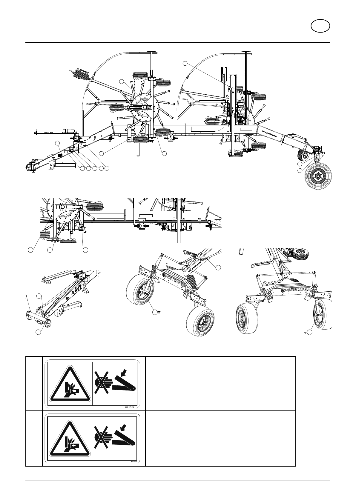
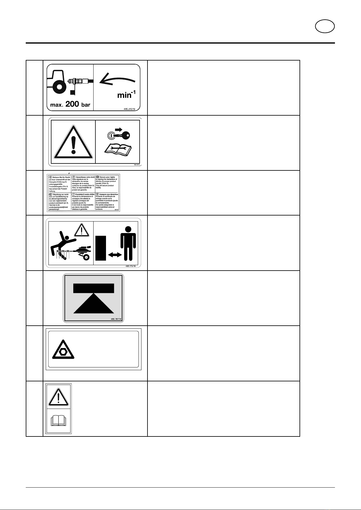
Meaning of warning signs.......................................... 5
SYMBOLS USED
CE mark..................................................................... 6
Safety hints: ............................................................... 6
WARNING SIGNS
GENERAL SAFETY TIPS
Travelling with implement in tow .............................. 10
Coupling and uncoupling the implement ................. 10
Regulations for Use ................................................. 10
Travelling on roads................................................... 10
Before starting work................................................. 10
Checking before operation....................................... 10
DESCRIPTION OF SERVICES
Overview...................................................................11
Tractor...................................................................... 12
Ballast weights......................................................... 12
Lifting unit (three-point linkage) ............................... 12
Necessary hydraulic connections ............................ 13
Power connections required .................................... 13
ATTACHING THE MACHINE
Attach the machine...................................................14
Fold up support stand...............................................14
Make electrical connections......................................14
Hydraulic connections...............................................14
Fit cardan shaft.........................................................14
Securing of unbraked devices by means of a tear-off
chain .........................................................................14
Adjusting the linkage at the transport securing
device ...................................................................... 15
Setting the rotor relief (optional)............................... 15
Parking the machine ................................................ 16
Adjusting the rotor stabilisation.................................17
Safety advice ........................................................... 18
TRANSPORT
Conversion from working position to transport
position .................................................................... 19
Driving on public roads ............................................ 20
Machine dimensions in transport position................ 20
Frame - chassis ....................................................... 21
Reducing the transport height ................................. 22
Operation of the tine holder ..................................... 22
OPERATION
General guidelines on working with the machine .... 23
Conversion from transport to working position......... 23
Settings on rotor chassis.......................................... 24
1. Set the lateral incline............................................ 24
2a Set raking height (mechanically)......................... 24
2b. Set raking height (hydraulic) .............................. 25
3. Align indicators to one another ............................ 26
Adjust feeler wheels................................................. 26
Cardan shaft speed ................................................. 27
Rear swath apron..................................................... 27
Dual-swath function (Optional equipment for TOP
722).......................................................................... 28
Swivelling from working to field transport position ... 29
Step sequence control............................................. 29
Single rotor operation (variant) ................................ 30
Setting the cam track............................................... 31
WORKING ON INCLINES
Take care when turning on inclines!......................... 32
GENERAL MAINTENANCE
Safety advice ........................................................... 33
General maintenance information............................ 33
Cleaning of machine parts....................................... 33
Parking in the open.................................................. 33
Winter storage.......................................................... 33
Articulated shafts..................................................... 34
Hydraulic unit........................................................... 34
General instructions regarding maintenance work... 35
Transmission (1.2).................................................... 35
Chassis.................................................................... 35
Set tyre tracking....................................................... 35
Tyres ........................................................................ 36
Tine arms................................................................. 36
Spring tines.............................................................. 37
Lubrication diagram ................................................. 38
Rotor unit ................................................................. 39
Disposal of old equipment ....................................... 40
Raising the machine ................................................ 40
AIR BRAKE SYSTEM
Coupling the air brake hoses ...................................41
Safety advice ............................................................41
Maintenance .............................................................41
Line filter cleaning ................................................... 42
Adapting to the tyres................................................ 42
HYDRAULIC BRAKE SYSTEM
Safety advice ........................................................... 43
Coupling the brake hose.......................................... 43
Maintenance ............................................................ 43
Adapting to the tyres................................................ 43
HYDRAULIC PLAN
TOP 722 hydraulic plan ........................................... 44
TOP 722 hydraulic plan - single rotor operation....... 45
TOP 722 hydraulic plan - single rotor operation and
hydraulic release...................................................... 46
TOP 722 hydraulic plan - single rotor operation,
hydraulic release and raking height ......................... 47
TOP 722 hydraulic plan - dual swath operation ....... 48
TOP 722 hydraulic plan - flow divider (optional) ...... 49
Hydraulic plan for TOP 812...................................... 50
TOP 812 hydraulic plan - single rotor operation........51
TOP 812 hydraulic plan - flow divider....................... 52
TECHNICAL DATA
Technical data.......................................................... 53
Connections required TOP 722................................ 53
Connections required TOP 812................................ 53
Optional equipment:................................................. 54
Designated use of the swath rotor ........................... 54
Type plate ................................................................ 54
Type plate position................................................... 54
SUPPLEMENT
Lubricants ................................................................ 61
Combination of tractor and mounted implement...... 64

- 5 -
1300_GB-INHALT_2862
Table of conTenTs EN
CE sign
The CE sign, which is affixed by the manufacturer, indicates outwardly that this machine
conforms to the engineering guideline regulations and the other relevant EU guidelines.
EU Declaration of Conformity
By signing the EU Declaration of Conformity, the manufacturer declares that the machine
being brought into service complies with all relevant safety and health requirements.
Meaning of warning signs
Do not enter rotor area while driving motor is running.
Never reach into the crushing danger area as long as
parts may move.
Stay clear of swinging area of implements
495.173

- 6 -
1801_EN-Sicherheit ANSI
EN
symbols used
CE mark
The CE mark, which is affixed by the manufacturer, indicates outwardly that this machine conforms to the engineering
guideline regulations and the other relevant EU guidelines.
EU Declaration of Conformity (see Attachment)
By signing the EU Declaration of Conformity, the manufacturer declares that the machine that
is brought into service complies with all relevant fundamental safety and health requirements.
Safety hints:
These Operating Instructions contain the
following Figures:
DANGER
If you do not follow the instructions in a text section
with this marking, there is a risk of fatal or life-
threatening injury.
• All instructions in such text sections must be
followed!
WARNING
If you do not observe the instructions marked this
way, there is the risk of a severe injury.
• All instructions in such text sections must be
followed!
CAUTION
If you do not observe the instructions marked this
way, there is the risk of an injury.
• All instructions in such text sections must be
followed!
NOTE
If you do not observe the instructions marked this
way, there is the risk of material damage.
• All instructions in such text sections must be
followed!
TIP
The text sections marked in this way provide you with
special recommendations and advise regarding the
economical use of the implement.
ENVIRONMENT
The text sections marked in this way provide practices
and advice on environmental protection.
The features marked as (optional) are only available as
standard with specific implement versions or are only
offered for specific versions as optional equipment or are
only offered in certain countries.
Figures may deviate from your implement in detail and are
to be taken as illustrations of operating principle.
Designations such as right and left always apply as the
direction of travel unless the text or illustrations clearly
show otherwise.

- 7 -
1800_GB-Warning signs_2858
EN
Warning signs
1
(2x)
Never reach into the crushing danger area as long as parts can move
there.
495.171
2
(2x)
Never reach into the crushing danger area as long as parts can move
there.
11 12 12
3
1
1
7
12
7
060-19-002
060-19-001
2
5 4 8 9
12 11
12
6
10
12
13

- 8 -
1800_GB-Warning signs_2858
Warning signs EN
3
(1x)
540
Preferred hydraulic pressure and cardan shaft speed.
495.310
4
(1x)
Farben:
Schrift und Grafik: verkehrsschwarz RAL 9017
Hintergrund: verkehrsgelb RAL 1023
Zuschnittlinie
116 mm
60 mm
05.09.16 5594/0006 donamar
Shut engine off and remove key before carrying out maintenance or
repair work.
495.165
5
(1x)
Secureyourrighttoproductwarrantybysigningthedeliverydeclaration.
495.713
6
(2x)
Do not enter the rotating rotors danger area. Wait until they have come
to a complete standstill.
7
(2x)
Vehicle jack lifting point
495.787
8
(1x)
494.695
Nach den ersten Betriebsstunden
Muttern bzw. Schrauben nachziehen.
Resserer les vis écrous après les 10
premières heures de fonctionnement.
Tighten nuts and screws after the
first 10 hours of operation.
Na de eerste 10 werkuren bouton en
moeren natrekken.
Retighten all screws after the first hours of operation.
494.695
9
(1x)
494.529
Read the operating instructions before putting the machine into
operation.
494.529

- 9 -
1800_GB-Warning signs_2858
Warning signs
EN
10
(2x)
Tyre pressure
495.668
11
(2x)
bsb 449 567
495.166
Do not enter the rotor arms swivel range
495.166
12
(12x)
A grease nipple position
494.646
13
(1x)
Cut cardan shaft to length
495.851

- 10 -
1800_EN-AllgSicherheit_3842
EN
Travelling with implement in tow
The attached implement influences the travelling
characteristics of the towing vehicle.
• Danger of tipping exists when working on slopes.
• The driving must be adapted to the corresponding
terrain and ground conditions.
• The towing vehicle is to
be sufficiently equiped
with weights at thefront
or at the rear in order to
guarantee the steering
and braking capacity (a
minimum of 20% of the
vehicle's tare weight on
the front axle).
• Transporting people on the implement is not
permitted.
Coupling and uncoupling the implement
• Danger of injury exists when coupling the implement
to the tractor!
• When coupling, do not stand between tractor and
implement while tractor is reversing !
• No-one must enter the area between tractor and
implement unless both vehicles have been secured
against rolling with wheel chocks !
• Drive shaft connection or disconnection is only to
be undertaken when the motor has stopped.
Regulations for Use
Regulations for Use: See chapter „Technical Data“.
• The trailer‘s load limits (permitted axle load, support
load, total weight) maynot be exceeded.The relevant
details are located on the right side of the trailer.
• In addition, observe the power limits of the tractor
being used.
Travelling on roads
• Observe the road rules
General safety tips
20%
Kg
Before starting work
a. Before commencing work, the operator must be aware
of all operating devices and functions.The learning
of these is too late after having already commenced
operation!
b. Before commencing any work check that implement
is safe for road travel and operation.
c. The danger of being crushed or cut exists in the Pick-
up, cutting unit, tailgate and upper extension areas.
d. Before driving the vehicle, the driver must ensure that
nobody will be endangered and that no obstructions
are present. If the tractor driver does not have a clear
view of the roadway immediatelybehind the implement,
he must be guided when reversing.
e. Observe the safety information fixed to implement.
An explanation of what the individual graphic warning
symbols mean can be found on page 5.
f. Observe also the tips in the respective chapters and
in the supplement to this operating manual.
Checking before operation
The following tips should make preparing the implement
for operation easier. Detailled information for individual
points can be found in the respective chapters in this
operating manual.
1. Check that all safety equipment (covers, casings, etc.)
is in good condition and fixed in the proper positions
of protection on the implement
2. Grease and oil the implement according to the
lubrication chart. Check the gearing for tightness and
the oil level.
3. Check that tyres have the correct air pressure.
4. Check that wheel nuts are sitting firmly.
5. Ensure the correct p.t.o.-r.p.m.
6. Make the electrical connections to the tractor and
check that they are correct. Take note of the tips in
the operating manual!
7. Carry out the following adaptions:
• Drawbar height
• Cardan shaft length
8. Secure the implement only with the equipment
provided.
9. Cut drive shaft to correct length and checkthat overload
safeguard is functioning (see Supplement)
10.
Check the electronic unit function.
11.
Connect hydraulic lines to tractor.
• Check hydraulic hoses for damage and wear.
• Ensure the correct connection.
12.
All swivelling parts must be secured against dangerous
position changes.
13.
Check parking brake and service brake functions.

- 11 -
1300_GB-ÜBERSICHT_2862
GB
descriPTion of serVices
Overview
Designations:
(1) Chassis
(2) Rotor unit right rear
(3) Swath apron
(4) Rotor unit left front
(5) Lower link attachment with support foot
(6) Inside feeler wheel
(7) Outside feeler wheel (optional)
(8) Spare wheel suspension for rotor chassis
2
3
5
6
4
1
7
8

- 12 -
2000-EN_Schleppervoraussetzungen_2862
EN
TracTor requiremenTs
Tractor
Thefollowingtractorrequirementsarenecessarytooperate
the implement:
- Tractor output: TOP 722: from 44 kW / 60
PS
TOP 812 from 52 kW /70
PS
- Attaching: Lower link Cat. II
- Connections: see"RequiredhydraulicsandElectrical
Connections" table"
Ballast weights
Ballast weights
The front of the tractor must have sufficient ballast weights
to guarantee braking and steering capabilities.
DANGER
Life hazard or material hazard - due to wrong tractor
ballast distribution.
• The front axle of the tractor must always be
loaded with at least 20% of the tractor's tare
weight to guarantee the steering and braking
capacity of the tractor/trailer unit.
20%
Kg
Lifting unit (three-point linkage)
371-08-16
371-08-16
- The tractor’s lifting unit (three-point linkage) must be
designed for the occurring load. (See technical data)
- The lifting struts are to be set at the same length (4)
using the appropriate adjusting device
(See the tractor manufacturer’s operating manual)
- Select the rear position if the lifting rods can be set in
various positions on the lower link. This relieves the
pressure on the tractor’s hydraulic system.
- The limiting chain or lower link stabilisers (5) are to
be set so that the attached machine CANNOT move
sideways. (Safety measure for transportation)

- 13 -
2000-EN_Schleppervoraussetzungen_2862
EN
TracTor requiremenTs
Necessary hydraulic connections
Design Consumer Single-acting
hydraulic connection
Double-acting
hydraulic connection
Standard Raising and lowering the rotor units X
Standard
(only TOP 812)
Moving the rotor units apart X
Optional
(onlyTOP722)
Dual swath device X
*) Floating (Neutral) position required
Power connections required
Design Consumer Pin Volt Power connection
Standard Lighting 7-pin 12 V DC According to DIN-ISO 1724
Optional Single rotor operation 2-pin 12 V DC according to DIN-9680

- 14 -
1900-DE_Anbau_2862
EN
aTTaching The machine
Safety
advice:
see Supplement A1
Point 8a. - h.)
Attach the machine
Attach the rake:
- Attach headstock on the lower linkage of the tractor
- Secure coupling pins correctly
- Position chassis frame horizontally
- The lower linkage limitation chains and/or stabilisers
are to be adjusted so that the attached machine
cannot move sideways.
Fold up support stand
- Fold up support stand after attaching the machine (5b).
- Press support stand down with your foot and fold up
- The bolt engages automatically
Make electrical connections
Lighting
- Attach 7-pin plug at tractor (E3)
- Check that the lighting functions on the machine
Hydraulic connections
Connect hydraulic lines to tractor
- Switch pto off before connecting
- Move lever of tractor's control unit to floating position
(0)
- Ensure clean plug connections
Beware!
Once released, the
support stand
swivels up auto-
matically
- Crushing hazard
- Connect hydraulic hoses
- Lay rope into tractor cabin
Fit cardan shaft
- Turn engine off and remove ignition key.
- Before fitting the cardan shaft, clean and grease the
machine's connection profiles and the pto.
- To start, fit the wide-angle joint with the freewheel
on the machine. Then attach cardan shaft to the
tractor pto.
- Secure the protective tubes of all cardan shafts
against rotating by attaching the securing chains.
Attention!
Check the cardan shaft length prior to
initial operation and adjust if necessary
025-05-04
L2
Shortest operating position possible (L2):
1. Lower hoist completely
2. Steering turned to lock.
(see adjacent illustration)
T rimming procedure
- To adjust the length, hold cardan shaft halfs in the
shortest operating position (L2) next to one another
and mark.
For details see chapter "Adapting the PTO shaft".
Securing of unbraked devices by means
of a tear-off chain
The operator must protect unbraked devices against loss
during travel by means of a tear-off chain. Mounting points
onthedeviceside depend onthetypeof connection. Please
refer to the illustrations below:
Beware!
Turn engine off
before mainte-
nance and repair
work, remove the
key and secure
the tractor against
rolling!

- 15 -
1900-DE_Anbau_2862
EN
AttAching the mAchine
1. Breakaway chain for lower link hitch:
094-18-402
2. Breakaway chain for rigid drawbar:
094-18-403
Adjusting the linkage at the transport
securing device
Adjustthelinkage of thetransport securingdevicecorrectly
before the first putting into operation. Check that the rotor
arms can be lifted hydraulically in locked status.
1. Lift unit to transport position
2. Control device in floating position
3. Loosen lower nut (1).
4. Screw upper nut (2) downwards until the rotor arm
lifts when you set the control device to "Lift".
5. Lock position with bottom nut (1)
1
2
Setting the rotor relief (optional)
- Park the machine on flat, firm ground.
- Bring the rotor to the working position.
- Secure the rotor relief spring using the chain on the
machine frame. The spring travel can be adjusted
by the number of chain links.
- The maximum spring travel in the working position
is 1400 mm. Measured from the inner end of the
spring to the outer end of the bolt.
1400 mm

- 16 -
1900-DE_Anbau_2862
EN
AttAching the mAchine
Parking the machine
The machine can be parked in the working or transport
positions.
Attention!
- Park the machine stably!
- Secure the machine against rolling with
wheel chocks.
- Control unit in floating position
- Release spring-loaded bolts (B)
- Swivel support stand (5a) up and allow to engage
- Pull cardan shaft (GW) off and place on support.
- Uncouple hydraulic lines (DW) from tractor.
- Remove rope from tractor cabin
- Disconnect electric cable (EL) from tractor
- Uncouple machine from tractor.
- Secure machine with anti-theft device
1. Install anti-theft device on the mounting
2. Secure the anti-theft device with a padlock.
Attention!
Only park
the machine on
flat, firm ground!
Attention!
Turn the tractor
engine off and
remove the key
before parking the
machine.

- 17 -
1900-DE_Anbau_2862
EN
AttAching the mAchine
Adjusting the rotor stabilisation
Attention!
Risk of injury due to crushing
Carry outadjustmentonlywhen the tractor
engine is switched off.
Remove ignition key and keep safe.
Adjust gyro stabilization:
After adjustment, the gyro units should hang horizontally
or slightly outwards.
Requirements:
1. Feeler wheels (option) are in working position
2. Fit tines to unused shaft stubs on both rotor units.
3. Set the desired rake height.
4. Switch on hydraulic supply
Setting:
5. Raise the gyro units until the wheels no longer touch
the ground.
6. Switch off hydraulic supply, remove ignition key and
store.
7. Adjust the spring via the threaded rod (1) until the
gyro units hang slightly outwards.
1
8. Switch on hydraulic supply
9. Raise and lower the rotors several times. The tines
should not penetrate the ground when the rotors are
lowered.
10.Repeat the procedure from point 5, if necessary.

EN
TransporT
2000_DE_TRANSPORT_2862 - 18 -
Safety advice
DANGER
Life-threateningdangerthroughmachinetippingover.
• Carry out the change from working position
to transport position, and vice versa, only on
level, firm ground!
DANGER
Life-threatening danger exists through moving parts
when changing from transport to working position.
• Make sure that the swivel range is clear and
that no-one is standing in the danger area.
• Do not enter the danger zone yourself.
DANGER
Life-threateningdangerexiststhroughrotatingrotors
when reducing the transport height.
• Switch off the pto shaft.
• Remove the tractor key!
• Wait until rotors comes to a complete stand-
still.
DANGER
Life-threatening danger exists through unsecured
rotor arms.
• Check the transport safety device before
each transport run! The gyro arms must be
locked with the hook. The locking hooks of
the transport lock (7) must be fully engaged
in the pivot of the outriggers.
• Check the position of the transport safety
device before each transport run. The cylin-
ders must be in the narrowest position!

EN
2000_DE_TRANSPORT_2862 - 19 -
TransPorT
Conversion from working position to
transport position
075-09-07
1. Raising the rotors at TOP 722
- Lift the rotors into field transport position using the
dual-action control unit (1).
- Completely retract the extendable rotor arms using
control unit (2) (only with the optionally available dual-
swath function)
- Pull rope (6) and lift the rotors completely with the dual-
action control unit (1).
- Release the rope.
- Check the correct locking of the transport securing
device (7).
TIP
If the lock does not hook in, reduce the gap between the
lifting hydraulic cylinders.
1. To do so, loosen the locknut at the outer hydraulic
cylinder and then reduce the gap.
2. Make sure that you do not exceed the adjusting range
(1) (91.5 mm ±5 mm).
ø35.5
H12
62.5
91.5
ø74
28
M36x1,5
±5
060-19-005
1
3. Retighten the lock nuts.
WARNING
Risk of an injury resulting in death or other serious
injury due to exceeding the adjusting range on the
hydraulic cylinder by the cylinder sheering.
• Make sure that you do not exceed the ad-
justing range (1) (91.5 mm
±5 mm
).
• Check the number of lprotruding screw
threads.
2. Raising the rotors at TOP 812
- Lift the rotors into field transport position using the
dual-action control unit (1).
- Completely extend the extendable rotor arms using
control unit (2)
- Pull rope (6) and lift the rotors completely with the dual-
action control unit (1).
- Release the rope.
- Check the correct locking of the transport securing
device (7).
6
7
- Completely retract the extended rotor arms with control
unit (2) to not exceed the statutory transport height.

EN
TransporT
2000_DE_TRANSPORT_2862 - 20 -
Driving on public roads
• Onlytransportthemachineinthetransportposition!
• Observethestatutoryregulationsforyourcountry.
• Driving on public roads may only be carried out as
described in chapter “Transport position”.
• Protective devices must be installed and in proper
condition.
• Before driving off, bring swivelling parts to correct
positionandsecureagainstdangerouspositionchanges.
• Checkthatthelightingfunctionsbeforedrivingoff.
WARNING
Risk of serious injury from protruding tines in
transport position.
• Put the protective strips (1) onto the tines
before lifting the rotor arms into transport
position.
Machine dimensions in transport
position
The following dimensions will not be exceeded if the trans-
port position is established correctly:
Type Height
(m)
Width(m) Length
(m)
TOP 722 3.99 2.54 8.90
TOP 722 with
wide driving
frame
3.99 2.80 8.90
TOP 812 3.99 2.80 9.70
This manual suits for next models
3
Table of contents
Other PÖTTINGER Farm Equipment manuals
Popular Farm Equipment manuals by other brands

Degelman
Degelman Tri-Plex Landroller 7645 manual

H&S
H&S TWIN MERGER Operator's manual and parts list

Tarter
Tarter CBFG Assembly and installation guide

MECHANICAL TRANSPLANTER
MECHANICAL TRANSPLANTER 1000 Operator's manual

MASSEY FERGUSON
MASSEY FERGUSON 8792 Service manual

Priefert
Priefert 04 Owner's/operator's manual

Moore Unidrill
Moore Unidrill 300G Instruction book

Raven
Raven SmarTrax installation manual

Raven
Raven SmarTrax John Deere 8R 2009 Series installation manual

Grouser
Grouser AG PRO PLUS HD Owner's manual & parts book

Standen
Standen POWAVATOR 400 Operator's handbook

Landoll
Landoll 2510 Series Operator's manual