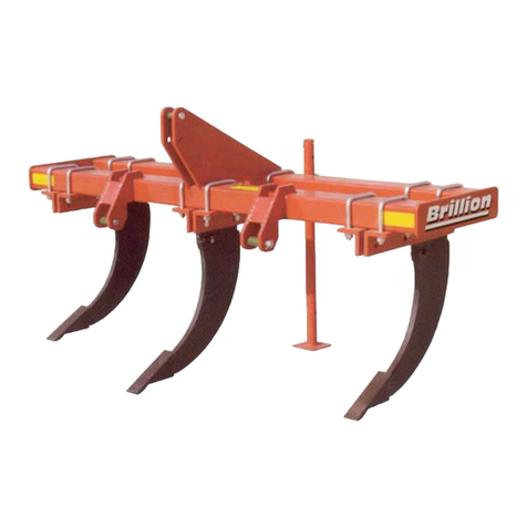
Brillion HFC Field Commander Series User manual

2K314
OPERATOR’S MANUAL
ASSEMBLY INSTRUCTIONS
BRILLION )$50(48,30(17
BRILLION, WISCONSIN 54110 2K314
1103rev3-31-05
MODELS: HFC16
THROUGH
HFC31
HFCT20
THROUGH
HFCT31
HFK16
THROUGH
HFK31
HFKT16
THROUGH
HFKT31
HFC Field Commander
Brillion
Brillion
www.brillionfarmeq.com

2K314

2K314
Introduction . .. .. .. .. .. .. .. .. .. .. .. .. .. .. .. .. .. .. .. .. .. .. .. .. .. .. .. .. .. .. .. .. .. .. .. .. .. 3
Location reference.. .. .. .. .. .. .. .. .. .. .. .. .. .. .. .. .. .. .. .. .. .. .. .. .. .. .. .. .. .. .. .. 3
Parts ordering .. .. .. .. .. .. .. .. .. .. .. .. .. .. .. .. .. .. .. .. .. .. .. .. .. .. .. .. .. .. .. .. .. .. 3
Safety Suggestions. .. .. .. .. .. .. .. .. .. .. .. .. .. .. .. .. .. .. .. .. .. .. .. .. .. .. .. .. .. .. .. .. .. 4
Safety Warning Signs. .. .. .. .. .. .. .. .. .. .. .. .. .. .. .. .. .. .. .. .. .. .. .. .. .. .. .. .. .. .. .. .. 5
Pre-operating Checks .. .. .. .. .. .. .. .. .. .. .. .. .. .. .. .. .. .. .. .. .. .. .. .. .. .. .. .. .. .. .. .. 7
Operating Instructions .. .. .. .. .. .. .. .. .. .. .. .. .. .. .. .. .. .. .. .. .. .. .. .. .. .. .. .. .. .. .. .. 10
Safety chain .. .. .. .. .. .. .. .. .. .. .. .. .. .. .. .. .. .. .. .. .. .. .. .. .. .. .. .. .. .. .. .. .. .. 10
Prepare for transport. .. .. .. .. .. .. .. .. .. .. .. .. .. .. .. .. .. .. .. .. .. .. .. .. .. .. .. .. .. .. 10
Prepare for field operation.. .. .. .. .. .. .. .. .. .. .. .. .. .. .. .. .. .. .. .. .. .. .. .. .. .. .. .. 11
Operating depth adjustment.. .. .. .. .. .. .. .. .. .. .. .. .. .. .. .. .. .. .. .. .. .. .. .. .. .. .. 11
Maintenance . .. .. .. .. .. .. .. .. .. .. .. .. .. .. .. .. .. .. .. .. .. .. .. .. .. .. .. .. .. .. .. .. .. .. .. .. 13
Fasteners .. .. .. .. .. .. .. .. .. .. .. .. .. .. .. .. .. .. .. .. .. .. .. .. .. .. .. .. .. .. .. .. .. .. .. .. 13
Shanks .. .. .. .. .. .. .. .. .. .. .. .. .. .. .. .. .. .. .. .. .. .. .. .. .. .. .. .. .. .. .. .. .. .. .. .. .. 13
Tires . .. .. .. .. .. .. .. .. .. .. .. .. .. .. .. .. .. .. .. .. .. .. .. .. .. .. .. .. .. .. .. .. .. .. .. .. .. 13
Lubrication.. .. .. .. .. .. .. .. .. .. .. .. .. .. .. .. .. .. .. .. .. .. .. .. .. .. .. .. .. .. .. .. .. .. .. .. 13
Assembly Instructions .. .. .. .. .. .. .. .. .. .. .. .. .. .. .. .. .. .. .. .. .. .. .. .. .. .. .. .. .. .. .. .. 16
Frame halves. .. .. .. .. .. .. .. .. .. .. .. .. .. .. .. .. .. .. .. .. .. .. .. .. .. .. .. .. .. .. .. .. .. .. 16
Tongue and clevis .. .. .. .. .. .. .. .. .. .. .. .. .. .. .. .. .. .. .. .. .. .. .. .. .. .. .. .. .. .. .. .. 16
Center rockshaft and wheels. .. .. .. .. .. .. .. .. .. .. .. .. .. .. .. .. .. .. .. .. .. .. .. .. .. .. 16
Cylinder anchor and braces .. .. .. .. .. .. .. .. .. .. .. .. .. .. .. .. .. .. .. .. .. .. .. .. .. .. .. 18
Center section wheel cylinders. .. .. .. .. .. .. .. .. .. .. .. .. .. .. .. .. .. .. .. .. .. .. .. .. .. 18
Leveling linkage .. .. .. .. .. .. .. .. .. .. .. .. .. .. .. .. .. .. .. .. .. .. .. .. .. .. .. .. .. .. .. .. .. 20
Wings and extensions.. .. .. .. .. .. .. .. .. .. .. .. .. .. .. .. .. .. .. .. .. .. .. .. .. .. .. .. .. .. 21
Wing rockshafts and wheels.. .. .. .. .. .. .. .. .. .. .. .. .. .. .. .. .. .. .. .. .. .. .. .. .. .. .. 22
Wing cylinder anchors and braces. .. .. .. .. .. .. .. .. .. .. .. .. .. .. .. .. .. .. .. .. .. .. .. 22
Wing wheel cylinders. .. .. .. .. .. .. .. .. .. .. .. .. .. .. .. .. .. .. .. .. .. .. .. .. .. .. .. .. .. .. 24
Gage Wheels for 16 ft to 19 ft wide machines.. .. .. .. .. .. .. .. .. .. .. .. .. .. .. .. .. .. 24
Wing lift cylinders .. .. .. .. .. .. .. .. .. .. .. .. .. .. .. .. .. .. .. .. .. .. .. .. .. .. .. .. .. .. .. .. 24
Wing support. .. .. .. .. .. .. .. .. .. .. .. .. .. .. .. .. .. .. .. .. .. .. .. .. .. .. .. .. .. .. .. .. .. .. 26
Hydraulic hoses .. .. .. .. .. .. .. .. .. .. .. .. .. .. .. .. .. .. .. .. .. .. .. .. .. .. .. .. .. .. .. .. .. 26
Shanks . .. .. .. .. .. .. .. .. .. .. .. .. .. .. .. .. .. .. .. .. .. .. .. .. .. .. .. .. .. .. .. .. .. .. .. .. .. 31
Shank locations .. .. .. .. .. .. .. .. .. .. .. .. .. .. .. .. .. .. .. .. .. .. .. .. .. .. .. .. .. .. .. .. .. 32
Light Kit .. .. .. .. .. .. .. .. .. .. .. .. .. .. .. .. .. .. .. .. .. .. .. .. .. .. .. .. .. .. .. .. .. .. .. .. .. 35a
Options.. .. .. .. .. .. .. .. .. .. .. .. .. .. .. .. .. .. .. .. .. .. .. .. .. .. .. .. .. .. .. .. .. .. .. .. .. .. .. .. 36
Spike Tooth Drags .. .. .. .. .. .. .. .. .. .. .. .. .. .. .. .. .. .. .. .. .. .. .. .. .. .. .. .. .. .. .. .. .. .. 37
Coil Tine Drags.. .. .. .. .. .. .. .. .. .. .. .. .. .. .. .. .. .. .. .. .. .. .. .. .. .. .. .. .. .. .. .. .. .. .. .. 41
Trouble Shooting.. .. .. .. .. .. .. .. .. .. .. .. .. .. .. .. .. .. .. .. .. .. .. .. .. .. .. .. .. .. .. .. .. .. .. 46
Specifications. .. .. .. .. .. .. .. .. .. .. .. .. .. .. .. .. .. .. .. .. .. .. .. .. .. .. .. .. .. .. .. .. .. .. .. .. 48
Contents
Contents
194rev3-4-05 Page 1
2K314

2K314
INTRODUCTION
To obtain maximum benefits from the BRILLION FIELD CULTIVATOR, please study this manual care-
fully before starting assembly or operation. A special section, “Assembly Instructions”, is included. If
items in this manual are not understood, contact your local Brillion dealer.
The Symbol Shown Is Used To Call Your Attention To Instructions
Concerning Your Personal Safety. This Symbol Is Found On Your
Machine - It Points Out Important Safety Precautions. It Means
“ATTENTION! - Become Alert! Your Personal Safety Is Involved!”
Read The Message That Follows And Be Alert To The Possibility Of
Personal Injury Or Death.
Location Reference
Right hand, left hand, and forward designations are determined by standing behind the machine and
facing the direction it will travel during field operation.
Parts Ordering
When ordering parts for this machine, include the complete model number and serial number. Refer to
the name plate on the tongue as shown in Figure 1. Please read and record this number upon taking
delivery of this machine.
FIELD CULTIVATOR Model ________________________
Serial Number __________________________________
Date Purchased _________________________________
Be sure to read the warranty card which is shipped
with the machine. Return the proper portion of the
card for recording at the factory.
BE ALERT!
Your Safety Is Involved.
194rev3-4-05 Page 3

2K314
Federal law requires you to explain the safety and operating instructions furnished with this machine to
all employees before they are allowed to operate the machine. These must be repeated to the employ-
ees at the beginning of each season. Be sure to observe and follow the instructions for the safety of
anyone operating or near the machine.
Investigation has shown that nearly 1/3 of all farm accidents are caused by careless use of machinery.
You can do your part in improving safety by observing the following suggestions. Insist that all people
working with you or for you abide by them.
1. Do not stand between the tractor and implement when attaching or detaching implement
unless both are not moving.
2. Before applying pressure to the system, be sure all connections are tight and that
hydraulic lines and hoses are not damaged.
3. Escaping fluid under pressure can be nearly invisible and have enough force to penetrate
the skin causing serious injury. Use a piece of cardboard or wood, rather than hands, to
search for suspected leaks. If injured by fluid, see a doctor at once.
4. Do not make adjustments or lubricate machine while it is in motion.
5. Do not allow anyone to ride on tractor or machine.
6. Always use transport locks while transporting the machine.
7. Do not transport at speeds over 15 mph. Use a tractor or towing machine heavier than the
machine.
8. Avoid sudden stops or turns when transporting because the weight of machine may cause
operator to lose control of tractor. Do not allow tractor drawbar to swing when in transport.
9. Use caution when towing behind articulated steering tractors; fast or sharp turns may
cause the machine to shift sideways.
10. When transporting the machine on a road or highway, use adequate warning symbols,
reflectors, lights, and slow moving vehicle signs as required. Use a safety chain.
11. Block machine so it will not roll when unhitched from tractor.
12. Relieve pressure in hydraulic lines before uncoupling hydraulic hoses from tractor. On
most tractors this can be done by operating valves after engine is stopped.
13. Securely block machine when working on or under it to prevent injury in case of hydraulic
failure or inadvertent lowering by another person.
14. Lower machine to ground when not in use.
15. Do not fold or unfold wings without first bleeding all air from the hydraulic circuit.
16. Know the height of your machine in the folded position, do not fold the wings under low
power lines or other obstructions.
17. Fold wings on as level a surface as possible.
Safety Suggestions
Safety Suggestions
194rev3-4-05 Page 4

2K314194rev3-4-05 Page 4A
The wings of the HFC Cultivator must not be raised by any other method than
using properly bled hydraulic cylinders provided with the machine.
If the wings have been raised by another method, and the cylinders are not filled with
oil, the unfolding sequence becomes extremely dangerous. Also, wings raised
by other methods could fall when transporting a machine over uneven terrain.
Do not remove the cylinder pins or service the cylinders unless the wings are un-
folded and supported.
DANGER
3J675
FALLING WINGS CAN CAUSE INJURY
OR DEATH. STAND CLEAR
WHEN WINGS
ARE BEING RAISED OR LOWERED.
USE COTTER PINS TO SECURE THE
CYLINDER PINS. DON NOT USE
THE HAIRPINS THAT MAY BE PACK-
AGE WITH YOU CYLINDERS--THEY
COULD POSSIBLY
COME LOOSE
EXTEND THE COTTER
PINS THROUGH THE
CYLINDER PINS AS
SHOWN --
DO NOT WRAP THE COTTER
PINS TIGHTLY AROUND THE
CYLINDER PINS
We have received reports that the hairpin that
holds the cylinder pin in place can come out.

2K314
Safety Signs
Safety Signs
194rev3-4-05 Page 5
The “WARNING” signs illustrated on this page and the next are placed on the machine to warn of
hazards. “The warnings found on the signs are for your personal safety and those around you.”
OBSERVE THESE WARNINGS!
There are three levels of hazard intensity that appear with the safety alert symbol on safety decals:
DANGER, WARNING, and CAUTION. The level of hazard intensity is defined as follows:
DANGER - Immediate hazards which WILL result in severe personal injury or death.
WARNING - Hazards or unsafe practices which COULD resutl in severe personal injury or death.
CAUTION - Areminder of safety practices, or an alert to unsafe practices which could result
in personal injury.
Keep these signs clean so they can be observed
readily. Wash with soap and water or cleaning
solution as required.
Replace “WARNING” signs should they become
damaged, painted over or if they are missing.
When replacing decals, clean the machine
surface thoroughly using soap and water
or cleaning solution to remove all
dirt and grease.
1. 5J333 Danger, Bleed air from wing cylinders
2. 3J675 Danger, Falling Wings Hazard
3. 9J629 Danger, Electrical Wires Hazard
4. 3K706 Warning, Hydraulic Leak Hazard
5. 8J310 Caution List
6. 5J333 Harrows... Drawbar Light
7. 4J230 Red Reflective
8. 4J231 Amber Reflective
9. 4K037 Brillion Logo
10. 4K038 Field Commander Decal
9
10
9
2
5
6
13
4
Both Wings Both Sides
Front & Rear
2
Both Wings
7
Both Wings
8

2K314
DANGER
BLEED THE AIR FROM WING LIFT CYLINDERS BEFORE
OPERATING. FAILURE TO DO SO WILL ALLOW WINGS TO
FREE FALL AND MAY CAUSE SERIOUS PERSONAL INJURY.
SEE OPERATOR’S MANUAL FOR CORRECT PROCEDURE.
3J678
CAUTION
HARROWS OR OTHER DEVICES MOUNTED ON THE REAR OF THIS
MACHINE WILL USUALLY MAKE IT DRAWBAR-LIGHT. TO AVOID
PERSONAL INJURY FROM MACHINE TIPPING REARWARD, ALWAYS
LOWER MACHINE TO GROUND BEFORE DISCONNECTING TRACTOR.
SEE OPERATOR’S MANUAL FOR DETAILS. 5J333
8J310
CAUTION
1. DO NOT LUBRICATE, ADJUST OR REPAIR WHEN MACHINE IS IN MOTION.
2. DO NOT TOW OR TRANSPORT FASTER THAN 15 MILES PER HOUR.
3. DO NOT RIDE OR ALLOW OTHERS TO RIDE ON THE MACHINE.
4. BLOCK UPALL HYDRAULICALLY OR MECHANICALLY RAISED COMPONENTS TO
PREVENT UNINTENDED LOWERING OR LOWER THE MACHINE TO THE GROUND TO
MAKE ADJUSTMENT OR REPAIRS WHEN NOT IN USE.
5. KEEP ALL PERSONSAWAY FROM MACHINE DURING HITCHING AND OPERATING.
6. SLOW DOWN BEFORE MAKING SHARP TURNS OR USING THE BRAKES.
DRIVE SLOWLY OVER ROUGH GROUND, SIDE HILLS, AND AROUND CURVES TO AVOID TIPPING.
7. COMPLY WITHALL LAWS WHEN TRANSPORTING THE MACHINE ON PUBLIC ROADWAYS.
8. INSTRUCT ALL OPERATORS IN THE SAFE OPERATION OF THE MACHINE.
REVIEW THE OPERATOR’S MANUAL FOR CORRECT PROCEDURES.
9. BLOCK IMPLEMENT TO PREVENT MOVEMENT WHEN UNHITCHED FROM TRACTOR.
10. KEEP ALL GUARDSAND SHIELDS IN PLACE WHILE MACHINE OR PARTSARE IN MOTION.
DANGER
WATCH FOR ELECTRICAL WIRES AND
OTHER OVERHEAD OBSTRUCTIONS
WHEN FOLDING WINGS.
FAILURE TO HEED THESE WARNINGS
MAY RESULT IN PERSONAL INJURY
OR DEATH. 9J629
10813A
WARNING
DO NOT GO NEAR LEAKS
•LOWER LOAD OR RELIEVE HYDRAULIC
PRESSURE BEFORE LOOSENING
FITTINGS.
•HIGH PRESSURE OIL EASILY PUNCTURES
SKIN CAUSING SERIOUS INJURY, GANGRENE
OR DEATH.
•IF INJURED, SEEK EMERGENCY MEDICAL
HELP. IMMEDIATE SURGERY IS
REQUIRED TO REMOVE OIL.
•DO NOT USE FINGERS OR SKIN TO
CHECK FOR LEAKS.
DANGER
3J675
FALLING WINGS CAN CAUSE INJURY
OR DEATH. STAND CLEAR
WHEN WINGS
ARE BEING RAISED OR LOWERED.
Field
Commander
4K038
Brillion
Brillion
4K037
5J333
Yellow & Black
3J675
Red & White
9J629
Red & White
3K706
Orange, Black & White
8J310
Yellow & Black
5J333
Yellow & Black
4K038
Wings Only
4K037
Wings Only
194rev3-4-05 Page 6a
1. 5J333 Danger, Bleed air from wing cylinders
2. 3J675 Danger, Falling Wings Hazard
3. 9J629 Danger, Electrical Wires Hazard
4. 3K706 Warning, Hydraulic Leak Hazard
5. 8J310 Caution List
6. 5J333 Harrows... Drawbar Light
7. 4K037 Brillion Logo
8. 4K038 Field Commander Decal

2K314
PRE-OPERATING CHECKS
Hydraulic cylinders
Before raising or lowering the wings, be sure that the wing lift cylinders are properly
bled (all air is removed from the hydraulic circuit). Improperly bled cylinders will
permit the wings to free-fall, possibly causing injury to the operator and damage
to the machine.
Bleed the system by removing the rod end pins which connect the cylinder to the wing and fully ex-
tend and fully retract the cylinders three or four times. Reconnect the cylinder rod ends to the wings.
Check to make sure that flow restrictors have been installed in the wing lift circuits. These are
screwed into the elbows in the wing lift hydraulic circuit as shown in figure 17. These restrictors
control the passage of oil to and from the wing lift cylinders and prevent the wings from falling too
rapidly.
Tractor hydraulic level
The wing lift and depth control cylinders are shipped from the factory without oil in them. If all 6
cylinders must be charged with oil, they will use approximately 5 gallons of oil. Check your tractor
hydraulic level to avoid any damage to the system.
Three point hitch position
Before moving the implement, be sure the three point lift arms of the tractor have been raised to
avoid damaging the tongue on the cultivator when making sharp turns.
Jack
Make sure the jack has been moved to the storage position on the drawbar and pinned in place.
Level adjust
1. With the tractor and the field cultivator on a level surface, check to make sure that the
machine is level from side to side.
a. Make sure that all cylinder anchor adjust rods are adjusted to the same length.
Check the indicator on the adjust tube to verify that all the anchors are adjusted equally.
b. With the tractor running, operate the hydraulic control lever for the wheel cylinders
to the extend position and hold it there until there is no movement in any of the wheel
cylinders.
c. Measure the pin center distances of the wheel cylinders, if they are all the same, (ap
proximately 28 1/4”), proceed to step 2, if the pin centers differ, retract the cylinders and
measure the pin centers if they are not all the same length (approximately 20 1/4”), adjust
the rod end clevis as necessary so that all cylinders are the same length. Make sure
that the rod end thread engages the clevis completely, and that the locking bolt on the
cylinder clevis is tightened.
194rev3-4-05 Page 7

2K314
d. Extend the cylinders and hold the control lever in the extend position until there is no
motion in any of the cylinders, check the pin center distances, if they are not all approxi
mately 28 1/4”, retract the cylinders, disconnect the pins from the wheel arms, and bleed
the air from the hydraulic circuit by extending and retracting the cylinders at least
3 times. At the end of each extend stroke, hold the hydraulic control lever at least 30
seconds, or until there is no movement in any of the cylinder rods.
e. Reconnect the cylinders to the wheel arms, and raise the machine by extending the
cylinders.
If your machine is less than 20 feet wide, proceed to step 3.
2. Measure to see that the wings are the same height from the ground as the center section.
a. If the heights are equal, proceed to step 4.
b. If the heights of either or both wings are different than the center section, adjust the
wing cylinder anchor brace rods until the wing is the same height as the center.
1. The wing cylinder anchor braces can be adjusted independently of each
other and independently from the center section.
2. Turn the adjust tube clockwise to raise the wing; counter-clockwise to lower
the wing.
3. 1 turn of the adjust tube will equal about 5/16 inch of height difference.
Note: You will have to lower the machine onto the shanks to be able to turn the adjust tubes.
Wing Cylinder Anchor Brace Rod
Adjust Tube
& Handle
Cylinder
Anchor
Depth Adjust
Depth Indicator
Cylinder
Lock
194rev3-4-05 Page 8

2K314
CENTER
ROCKSHAFT
GAGE WHEEL
ADJUST BAR
16’ WING
LEVELING
LINK
LEVLING
LINKAGE
ADJUST
TONGUE
WALKING
BEAM
3. If your machine is 16 feet through 19 feet wide, the wing gage wheels are used only to
control the operating depth. Check to make sure that the machine is level in the
operating position. If it is not, set the wing gage wheel to a higher or lower position by
using different holes in the gage wheel adjust bar. See Figure 3A.
4. Measure to see if the machine is level from front to rear.
a. If the front of the machine is higher than the rear, shorten the leveling linkage between
the tongue and leveling link by using the handle on the brace tube to turn the
leveling link clockwise.
b. If the rear is higher than the front, lengthen the leveling linkage (turn counter-clockwise).
194rev3-4-05 Page 9

2K314
OPERATING INSTRUCTIONS
DO NOT allow others on or near the tractor and the machine when operating or
preparing to operate the machine.
Prepare the machine for transport
1. Extend the transport wheel cylinders completely. These are series cylinders and are
designed to raise the machine evenly. The cylinders will rephase or equalize at the end
of their stroke. Simply continue to hold the hydraulic control lever of the tractor in the
extend position until all cylinders in the system are completely extended. Do this occasion-
ally during operation at the end of the rows to make sure that the cylinders remain in phase.
2. With the machine in the up or transport position, raise the wings to folded position.
Know the folded height of your field cultivator and any attachments. Be sure that
you are not under any electrical lines or any other obstruction that could cause
injury to the operator or damage to the equipment.
3. Use the transport locks to lock the machine in the transport position. See figure 3.
Maximum road speed is 15 MPH under good conditions. Do not tow the machine
at a speed at which the operator loses control of his vehicle.
It is the responsibility of the owner/operator to comply with all applicable laws regarding slow moving
vehicle signs, warning lights, reflectors, and safety chains.
Safety Chain
Use of a safety chain is recommended if the machine is towed on a public road or highway. Total
weight of towed machine must not exceed chain capacity as shown on the chain’s identification tag.
Such a chain, along with hardware to attach to the Field cultivator is available as Kit #1K822.
See illustration below and install as shown (not all of the hardware will be used). Slack in the chain
should be only enough to permit turning. Distance from hitch pin to attachment point or intermediate
support should not exceed 9”.
CAUTION If two or more machines are pulled in tandem, a larger chain may be
required. Chain capacity must be greater than the total weight of towed
implements. A second chain should be used between each implement.
CAUTION Replace chain if one or more links are broken, stretched, or otherwise
damaged or deformed.
Keep attaching hardware fastened securely.
If bolts are replaced, be sure to use grade 5 or higher.
If you have any questions regarding the safety chain call your Brillion dealer.
194rev3-4-05 Page 10

2K314
Prepare the machine for field operation
1. Raise the machine fully on its transport wheels.
2. Remove the transport locks on both center axle lift cylinders and place them in their stor
age position. See figure 3.
3. Lower the wings by extending the wing lift cylinders. Make sure that the cylinders are
extended completely, this will allow the wings to float down to follow the contour of the
ground.
Operating depth adjustment
1. With the machine leveled, the transport locks removed, and the wings unfolded, set the
approximate working depth by adjusting the cylinder anchor brace rods. See figure 6.
The scales on the anchor adjust rods are used to make sure that the brace rods are set
equally. The wing operating depth can be adjusted independently of the center section
by changing the anchor rod length as required. Shortening the brace tube raises the wing,
decreasing the operating depth. Lengthening the brace tube increases operating depth.
Note: The wing operating depth of 16 through 19 foot wide machines is controlled by
pinning the gage wheel adjust bar where required.
Note: Lower the machine onto the shanks to turn the adjust tubes.
Important: Adjust both anchor braces on the center section equally. Unequal length
braces will put a strain on the center axle, center frames, and on hydraulic cylinders.
FIGURE 5
194rev3-4-05 Page 11

2K314
Figure 6
2. Level the machine front to rear by adjusting the leveling linkage as required. Lengthening
the linkage raises the front, shortening the linkage lowers the front.
NOTE: In operation, the adjustment of wing gage wheels will probably be different than
the center section. This is due to the difference in tires and also because the wheels of
the center section are probably following in the tractor tire tracks. The best way to check
if the machine is level, is to make all the adjustments, lower the machine into the operat
ing position, then drive forward several feet. Now, stop, slowly raise the machine and watch
as the sweeps of the field cultivator come out of the ground. They should all come out at
the same time. If the front of the machine comes out of the ground before the rear, lower
the front of the cultivator. If the wings come out of the ground before the center, set the
wings to operate deeper and vice versa.
3. After the machine has been leveled in the operating position, operate a few feet and verify
the operating depth. The depth can now be changed by adjusting all brace rod tubes
equally.
194rev3-4-05 Page 12

2K314
MAINTENANCE
Fasteners
After a few hours use, check entire machine and tighten any loose nuts or bolts. Daily or periodic
checks should be made thereafter.
Shanks
After 5 hours of operation, and every 50 hours thereafter, check to make sure that the shank pivot
bolts are tight. Loose pivot bolts will permit the bushing to rotate in the spring holder causing the
holes to wear, resulting in sloppy shank support.
Tires
The wheels furnished with the FIELD CULTIVATOR are designed for use with 9.5L-15, 8 ply rib
implement tires on the center section, 7.60-15, 6 ply rib implement tires are used on the wings when
they are equipped with walking beams. When single tires are used on the wings, 9.5L-15, 8 ply tires
are used. Wing gage wheels on the 16 through 19 foot wide models are designed for use with 6.70-
15, 4 ply or 7.60-15 4 ply tires. These tires must be inflated to 44 psi.
NOTE: USE OF SMALLER OR LIGHTER TIRES WILL CAUSE PREMATURE TIRE
FAILURE AND MAY CAUSE AN ACCIDENT.
Lubrication
Lubricate your field cultivator at the locations shown in figure 7. The number in the lubrication sym-
bol indicates the hourly interval between greasing.
Always lubricate your field cultivator before taking it to the field for the first time.
Lower the implement unto the shanks before greasing.
Replace any missing fittings and clean all fittings before greasing.
Wheel bearings and walking beam bearings should be repacked annually. Follow the disassembly
and reassembly procedures on page 15 figure 8 when repacking these bearings.
When the machine is not to be used for some time, exposed portions of the cylinder rods should
be cleaned and covered with a thick coat of grease. This will prevent corrosion which will damage
seals.
194rev3-4-05 Page 13

2K314
FIGURE 7
194rev3-4-05 Page 14

2K314194rev3-31-05 Page 15
FIGURE 9
Hose
Clamps
Manual
Cannister

2K314
ASSEMBLY INSTRUCTIONS
1. Frame halves.
A. Support the two frame halves on supports of equal height. Position the frame
halves as shown in figure 9 on page 15.
B. Loosely bolt the halves together with (4) 5/8 x 1 1/2” long capscrews, lockwashers,
and nuts on the rear side plate, and (3) 3/4 x 2” long capscrews, lockwashers, and
nuts at the front plates. The heads of the bolts must be to the inside of the drawbar
as shown.
C. Attach the plates of the left frame with (6) 5/8 x 4 11/16 x 5 1/2” deep U-bolts,
lockwashers, and nuts. DO NOT TIGHTEN UNTIL AXLE IS IN PLACE.
D. Using the 1 1/4” diameter pivot pin that will be used to attach the tongue to the
drawbar, make sure that the holes for this pin align. Tighten the 3/4” bolts on the
hitch plates. Make sure that the pivot pin holes remain in alignment while
tightening the bolts.
2. Tongue to the drawbar and the clevis to the tongue.
A. Install a grease zerk into the tongue. This is a self-tapping fitting (found in the box
with the pivot pin) and should be turned into the hole.
B. Attach the tongue to the drawbar with the pivot pin. Loosen one of the nuts
connecting the drawbar brace to the drawbar and use this bolt to lock the pivot
pin in place. Turn a 1 1/4” locknut on to the pivot pin. Do not over-tighten, (tongue
must be able to pivot). Attach the hitch to the tongue with a 1 1/4” x 9 1/2” long
capscrew and locknut.
3. Center rockshaft and wheels.
A. Mount (4) 9.5L-15,8 ply tires on the 15 x 8LB rims and attach to the hubs of the
center rockshaft.
Note: If your FIELD CULTIVATOR is equipped with S-tines, the spindle should be
bolted in the hole in the sleeve (of the walking beam) which will position the wheel
farthest from the wheel arm. This will prevent the tire from contacting the tine in the
transport position.
C. Apply some grease to the bearing saddles on the frames, and lower the center
rockshaft and wheels into the bearings. The cylinder anchors must be in the “up”
position shown in figure 10 when positioning the rockshaft.
D. Apply some grease to (4) bearing caps and use them to trap the rockshaft in
place. Secure with (8) 3/4 x 2” long capscrews, lockwashers, and nuts. TIGHTEN
THESE BOLTS THEN TIGHTEN ALL FRAME HARDWARE.
194rev3-4-05 Page 16

2K314
FIGURE 10
194rev3-4-05 Page 17
This manual suits for next models
8
Table of contents
Other Brillion Farm Equipment manuals

Brillion
Brillion SOIL BUILDER II User manual

Brillion
Brillion Zone Commander ZS33O1 User manual

Brillion
Brillion Land Commander III LCS5303-4 User manual

Brillion
Brillion SCP-23 Instruction Manual

Brillion
Brillion CPP-7 Series User manual

Brillion
Brillion Compaction Commander 03 Series User manual

Brillion
Brillion Zone Commander ZSF-8301 User manual

Brillion
Brillion Landcommander II LCS3302 User manual

Brillion
Brillion Zone Commander ZM3302 User manual

Brillion
Brillion PPF Series Use and care manual