Brillion OVERSEEDER User manual

7K116
OPERATOR’S MANUAL
ASSEMBLY INSTRUCTIONS
700rev7-11-03
BRILLION FARM EQUIPMENT
BRILLION,WISCONSIN 54110
7K116
MODELS: BOS6S BOS6F BOSB6S BOSB6F
BOS4S BOS4F BOSB4S BOSB4F
OVERSEEDER
GRASS SEEDER
www.brillionfarmeq.com

7K116

7K116
Introduction ............................................................................................................................................... 3
Location Reference........................................................................................................................... 3
Parts Ordering................................................................................................................................... 3
Safety Suggestions................................................................................................................................... 4
Safety Warning Decals .................................................................................................................... 6
Safety Decal Location ....................................................................................................................... 7
Pre-Operating Instructions ....................................................................................................................... 8
Hardware/Tightening Torques .......................................................................................................... 8
Chain Tension ................................................................................................................................... 9
Lubrication....................................................................................................................................... 11
Seed Rate Alighnment .................................................................................................................... 13
Drive Shaft Clutch ........................................................................................................................... 14
Rear Roller Alignment ..................................................................................................................... 15
Storage............................................................................................................................................ 16
Operation................................................................................................................................................ 17
Attaching to Tractor ........................................................................................................................ 17
Transport......................................................................................................................................... 19
Seed Rate Adjustment .................................................................................................................... 20
Seed Rate Calibration & Seed Charts ............................................................................................21
Operating Depth.............................................................................................................................. 23
Seeding ........................................................................................................................................... 24
Troubleshooting .............................................................................................................................. 25
Maintenance ........................................................................................................................................... 26
Lubrication....................................................................................................................................... 26
Chain Tension ................................................................................................................................. 28
Rotor Tines...................................................................................................................................... 30
Acre Meter....................................................................................................................................... 31
Options ................................................................................................................................................... 32
Gage Wheels .................................................................................................................................. 32
Second Seed Box............................................................................................................................ 33
SlowDownKit .................................................................................................................................. 34
Speed Up Kit ................................................................................................................................... 35
Acre Meter Kit.................................................................................................................................. 36
Seed Placement Kit......................................................................................................................... 37
Rear Coil Tine Kit ............................................................................................................................ 42
Warning Light Kit............................................................................................................................. 43
Machine Specifications........................................................................................................................... 44
CONTENTS
PageI
900rev601

7K116

7K116
The Brillion Turfmaker Overseeder was
designed to be used primarily for seeding for
new growth in existing stands of grass, turf, etc.
To obtain maximum benefits, please study this
manual carefully before operating or starting
assembly of optional equipment .
If items covered in this manual are not under-
stood, contact your local Brillion dealer.
This safety alert symbol
is used to call your
attention to instructions
concerning personal
safety. This symbol is found throughout this
manual and will be found on your machine. It
points out important safety precautions. It
means “ATTENTION! BECOME ALERT!
YOUR SAFETY IS INVOLVED!” Read the
message that follows and be alert to the possi-
bility of personal injury or death.
SAFETY ALERT
Parts Ordering
When ordering parts for this machine, include
the complete model number and serial number.
Refer to the name plate on the inside of the
frame’s right hand end plate. Please record
these numbers upon taking delivery of the unit.
INTRODUCTION
Location Reference
Right hand, left hand and forward designations
are those related to the operator when sitting in
theoperatingposition.
Be sure to read the warranty form which is
shipped with the machine. Return the proper
portion of the form for recording at the factory.
Figure 1
NamePlate
LocatedHere.
SeederModel
Serial Number
Date Purchased
INTRODUCTION
Page3
900rev601

7K116
Federal law requires that you explain the safety and operating instructions
furnishedwiththismachinetoallemployeesbeforetheyareallowedtooperate
the machine. These must be repeated to the employees at the beginning of
each season. Be sure to observe and follow the instructions for the safety of
anyone operating or near the machine.
Investigationhasshownthatnearlyone-thirdofallfarmaccidentsarecaused
by careless use of machinery. You can do your part in improving safety by
observingthefollowingsuggestions. Insistthatallpeopleworkingwithyouor
for you abide by them.
1. Do notstandbetweentractorandimplement
when attaching or detaching implement
unless both are not moving.
2. Do not make adjustments or lubricate or
clean knives while machine is in motion.
3. Do not allow anyone to ride on tractor or
machine.
4. Donotallowanyonetoremaininthevicinityof
the machine when starting or operating.
5. Remain on the tractor when Power-take off
is in motion.
6. Do not operate in excess of standard
Power-take-off speed.
7. Keepyourself,clothing,hands, andallothers
well clear of rotating drive line, PTO and all
moving parts.
8. Keep all guards in place. Replace any that
become damaged.
9. Do not transport at speeds over 20 mph.
10. Avoid sudden stops or turns when trans
porting because weight of machine may
causeoperatortolosecontroloftractor. Use
a tractor or towing vehicle heavier than the
machine.
11. It is best not to transport a seeder with a
full box. Always be sure the front of the
tractorhasenoughweighttomaintaincontrol
iftransporting aseederwhenthereisseedin
the seedbox.
12. When transporting the machine on a road or
highway, use adequate warning symbols,
reflectors, lights, and slow moving vehicle
signs as required.
13. We recommend the installation of safety
lights on this machine. Due to its bulk and
size, the safety ligts on your tractor may be
hidden during transportation. See page 43 -
Optional Equipment.
14. Escaping hydraulic fluid under pressure can
have sufficient force to penetrate the skin,
causing serious personal injury. Before
applying pressure to the system, be sure all
connections are tight and that the lines and
hoses are not damaged.
15. Hydraulic fluid escaping from a very small
hole can be almost invisible. Use a piece of
cardboard or a piece of wood, rather than
hands, to search for suspected leaks.
16. Securely block machine when working on or
under it to prevent injury in case of hydraulic
failure or inadvertent lowering by another
person.
17. Lower machine to ground when not in use.
18. Block machine so it will not roll when
unhitched from tractor.
SAFETY SUGGESTIONS
Page 4
900rev601

7K116
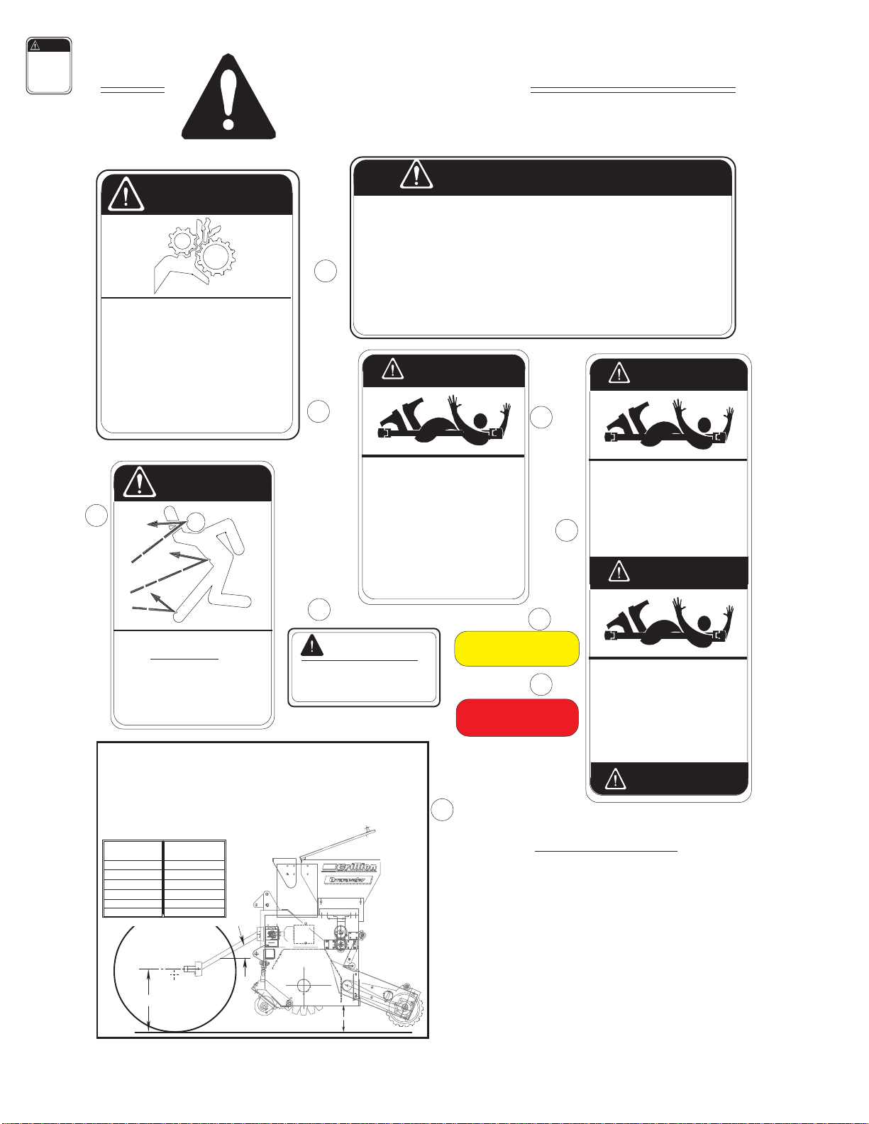
There are three levels of hazard intensity that
appear with the safety alert symbol on safety
decals: DANGER, WARNING, and CAUTION.
The level of hazard intensity is determined by the
followingdefinitions:
DANGER - Immediate hazards which
WILL result in death or serious
personal injury.
WARNING - Hazards or unsafe practices
which COULD result in death or
serious personal injury.
CAUTION - Indicates potentially hazardous
situations, or directs attention to
unsafe practices which could
result in minor or moderate injury.
•Examinesafety decalsandbesureyou have
the correct safety decals for the machine.
•Order replacement decals through your
BRILLIONdealer.
•Keep these signs clean so they can be
observedreadily. Itisimportanttokeepthese
decals cleaned more frequently than the
machine. Wash with soap and water or
cleaning solution as required.
•Replace decals that become damaged or
lost. Also be sure that any new machine
components installed during repair include
decals which are assigned to them by the
manufacturer.
•When applying decals to the machine, be
sure to clean the surface to remove any dirt
or residue. Wherepossible, sign placement
should protect the sign from abrasion, damage,
or obstruction from mud, dirty oil, etc.
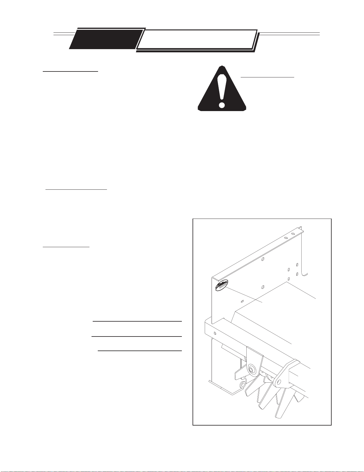
•Information and identification decals are
shown below. Safety decals for the
Overseeder and their locations on the
machine are pictured onthe following
twopages.
PLANTING RATES FOR SEED BOX
CALIBRATION OF SEED BOX
1. Rates arefor13-ToothDriver. Doubletheserates for26-ToothDriver.
2. Rates areintendedasa guide only. Variationin size andcleanlinesswill
affectrates. Checkacreage & Lbs.ofseedused for bestresults.
13-Tooth
Driver
(Usingthe26-toothSprocket
doublestheseedrateshown.)
Large Seed Box May Be Calibrated as Follows:
1. Raisemachine&lockin transport position.
2. Closetheseedboxonthesmallseedbox (if one ispresent.)
2. Placeatarpundermachineto collect seed.
3. Turnthe 37Toothsprocket clockwise as follows:
-82revolutionsfor6 Foot Seeder
-122revolutionsfor4Foot Seeder
4. Weighseedandmultiplyby10(20for
26-ToothDriver)
forapproximate
plantingrate
inlbs/acre.
7K218
37-Tooth
Driven
PoundsPer Acre Pounds Per 1000Sq. Ft.
123456 78 12 34 5 6 7 8
24 45 85 155 207 259 338 389
24 45 95 161 254 309 380 462 .52 1.03 1.94 3.55 4.76 5.95 7.76 8.92
.52 1.03 2.18 3.70 5.83 7.10 8.74 10.61
Indicator Setting
KENTUCKYBLUEGRASS
TALLFESCUE
*Willcracksome seeds at
thesesettings. Not
recommended: Lentils,
Sorgum.SidanGrass
12
10
11
SAFETY DECALS
SAFETY DECALS
Page 5
INFORMATION & IDENTIFICATION DECALS
10. 7K218-SeedChart,Large Seedbox
[7K217 - Seed Chart, optional Small Seedbox]
11. 7K240-Decal,“BRILLION”
12. 6K402-Decal,“OVERSEEDER”
900rev601

7K116
Figure 2A
SAFETY DECALS
1. 2K123-MovingPartsWarning
2. 8J310-CautionDecal
3. 4K031-ThrownObjectWarning
4. 5D019-540TransmissionCaution
5. 2J431-ReflectiveAmber
6. 2J430-ReflectiveRed
7. 7K010 - Lifting Instructions
8. 3K696-DangerRotatingDriveline
9. 7K009-DangerGurardMissing
MOVINGPARTHAZARD
TO PREVENT SERIOUS INJURY
FROMMOVINGPARTS:
•KEEP COVERS CLOSED DURING
OPERATION.
•DO NOT ALLOW ANYONE TO RIDE
OR CLIMB ON MACHINE DURING
OPERATION.
•KEEP OBSERVERS AWAY.
CAUTION
2K123
THROWNOBJECTHAZARD
TO PREVENT SERIOUS INJURY OR DEATH
FROM THROWN OBJECTS, KEEP AWAY
FROM DISCHARGE AREA DURING
OPERATION.
KEEP OTHERS OUT OF VICINITY WHILE
OPERATING. 4K031
KEEPAWAY!
WARNING
3
2
1
OVERSEEDER DECALS
45
THIS TRANSMISSION BOX
FOR540 RPM ONLY!
CAUTION
5D019
3K696
DONOTOPERATEWITHOUT-
DANGER
•ALL DRIVELINE, TRACTOR, AND
EQUIPMENT SHIELDS IN PLACE.
•DRIVELINES SECURELY ATTACHED
AT BOTH ENDS
•DRIVELINE SHIELDS THAT TURN
FREELY ON DRIVELINE
DANGER-ROTATINGDRIVELINE
CONTACT CAN CAUSE DEATH
KEEPAWAY!
9
8
GUARD MISSING
DO NOT OPERATE
DANGER
7k009
GUARD MISSING
DO NOT OPERATE
DANGER
DANGER
CAUTION
1. DO NOT LUBRICATE, ADJUST OR REPAIR WHEN MACHINE IS IN MOTION.
2. DO NOT TOW OR TRANSPORT FASTER THAN 15 MILES PER HOUR.
3. DO NOT RIDE OR ALLOW OTHERS TO RIDE ON THE MACHINE.
4. BLOCK UP ALL HYDRAULICALLY OR MECHANICALLY RAISED COMPONENTS TO
PREVENT UNINTENDED LOWERING OR LOWER THE MACHINE TO THE GROUND TO
MAKE ADJUSTMENT OR REPAIRS WHEN NOT IN USE.
5. KEEP ALL PERSONS AWAY FROM MACHINE DURING HITCHING AND OPERATING.
6. SLOW DOWN BEFORE MAKING SHARP TURNS OR USING THE BRAKES.
DRIVE SLOWLY OVER ROUGH GROUND, SIDE HILLS, AND AROUND CURVES TO AVOID TIPPING.
7. COMPLY WITH ALL LAWS WHEN TRANSPORTING THE MACHINE ON PUBLIC ROADWAYS.
8. INSTRUCT ALL OPERATORS IN THE SAFE OPERATION OF THE MACHINE.
REVIEW THE OPERATOR’S MANUAL FOR CORRECT PROCEDURES.
9. BLOCK IMPLEMENT TO PREVENT MOVEMENT WHEN UNHITCHED FROM TRACTOR.
10. KEEP ALL GUARDS AND SHIELDS IN PLACE WHILE MACHINE OR PARTS ARE IN MOTION.
8J310
CAUTION
Page 6
900rev7-11-03
MAXLIFT HEIGHT
TOAVOIDDAMAGETOPOWERTAKEOFFSHAFTJOINTS
THEOPERATINGANGLE OFTHEPTO SHAFTSHOULDNOTBESTEEPERTHAN
30DEGREES WHENTHE SHAFTIS TURNING. SET LIFTSTOPSONTHETHREE
POINTLIFT ACCORDINGTO THECHART BELOW. THE OVERSEEDERCAN BE
TRANSPORTEDIN A HIGHERPOSITIONWITH THE POTDISENGAGED. DONOT
ENGAGETHE PTOBEFORELOWERING THEMACHINE.
TRACTOR PTO
SHAFT HEIGHT
TRACTOR PTO
SHAFT HEIGHT MAXIMUM LIFT
HEIGHT
21” 9”
22” 10”
23” 11”
24” 12”
25” 13”
26” or Greater 14”
30O
7
6

7K116
Avoid Damage to PTO Joints
DECAL LOCATIONS
Figure 2B
PLANTING RATES
CALIBRATIONOF SEED
Indicator PoundsPer PoundsPer
7K218
1. Rates arefor13-Tooth Driver. Doublethese
SeedBox MayBeCalibrated for
UnlistedSeed asFollows:
1. Raise machine &lock in
transportposition.
2. Place a tarpunder machineto
(Usingthe 26-tooth
MOVING PART HAZARD
TOPREVENTSERIOUSINJURY
FROMMOVINGPARTS:
•KEEPCOVERSCLOSED DURING
OPERATION.
•DONOTALLOW ANYONETORIDE
ORCLIMBON MACHINEDURING
OPERATION.
•KEEPOBSERVERSAWAY.
CAUTION
2K123
1. 2K123-MovingPartsWarning
2. 8J310-CautionDecal
3. 4K031-ThrownObjectWarning
4. 5D019-540TransmissionCaution
5. 2J431-ReflectiveAmber
6. 2J430-ReflectiveRed
7. 7K010 - Lifting Instructions
8. 3K696-DangerRotatingDriveline
9. 7K009-DangerGuardMissing
10
2
3
35
12
11
5
11
12
6(BothEnds)
(Under
Cover)
1
10. 7K218-SeedChart
11. 7K240-Decal,“BRILLION”
12. 6K402-Decal,“OVERSEEDER”
DANGER
CAUTION
1 (under cover &
near gears:
Rt. Side)
900rev7-11-03 Page 7
4
8,
9
7

7K116
Your Brillion Turfmaker Overseeder will come to
you fully assembled from the the factory. Before
operating, thereare anumber ofitemsthat should
be checked to insure safety and smooth running.
PRE-OPERATING INSTRUCTIONS
1. Check all hardware for tightness
UsetheTightening TorqueChartreproduced
below as a guide.
1/4-20 5 8 12 5/7 7/10
THREAD
SIZE
BOLT/ NUTTIGHTENING TORQUES
BOLT GRADE PLATED, STOVER
LOCK NUTS
grade 2 grade 5 grade 8 grade B grade C
min/max min /max
5/16-18 11 17 24 10/12 11/16
3/8-16 20 30 45 15/20 20/28
7/16-14 30 50 70 23/32 31/43
1/2-13 50 75 105 37/50 45/62
9/16-12 70 110 155 50/70 70/95
5/8-11 100 150 210 70/95 90/122
3/4-10 170 270 375 125/165 155/210
7/8-9 165 430 610 185/250 225/312
1-8 250 645 910 275/375 360/462
1 1/8 - 7 355 795 1290
1 1/4 - 7 500 1120 1820
1 3/8 - 6 745 1670 2710
1 1/2 - 6 870 1950 3160
VALUESGIVEN AREINFOOT-POUNDS
FORFINETHREADSERIES,MULTIPLYVALUESBY1.1
USE GRADE BLOCKNUTSWITHGRADE 2AND GRADE5BOLTSONLY.
USEGRADECLOCKNUTSWITHGRADE8 BOLTSONLY.
PRE-OPERATING INSTRUCTIONS
Page 8
900rev601

7K116
Figure 3a
(1-BoxMachine)
2. Chain Tension
2a. Seedmeter Drive Chains -
Note:These chains operate best with a slight
amount of looseness. A brand new
chain should be tight, but as the machine
is broken in, chain stretch will result in
looseness.
Figure 3b
(2-BoxMachine)
ADJUSTSEEDMETER
DRIVECHAINSHERE ADJUST
SEEDMETER
DRIVECHAINS
HERE
If chains do need to be adjusted,
Thediagrams below show thepointsatwhich
the tension adjustment can be made.
Loosen nuts at points indicated and adjust
desired amount -- retighten nuts.
If any guards are removed for
lubricating, they must be replaced
before operating.
Page 9
900rev601

7K116
2. Chain Tension
2b. Rotor Drive Chains -
•With drive disengaged:
1. Loosen jam nut and tighten set screw
until slight load is felt against set screw.
2. Back off 1/2 turn and lock jam nut.
With drive operating at 540 RPM:
1. Loosen jam nut and tighten set screw
until drive becomes noisy, then back off
until noise is reduced.
2. Lock in place with jam nut.
JAM NUT
JAM NUT
Figure 4
FRONT
of Machine
Page 10
900rev7-11-03
CARRIAGE
BOLT

7K116
To check oil level:
1. Remove mast tie plate.
2. Clean the area around the top pipe plug.
3. Remove pipe plug from gear box.
4. Usingaflashlight,checkto see that the oil
level is visible in the gear box. If needed,
dip a CLEAN wooden stick into the box to
check the oil level and the cleanliness of
theoil.
•Lubricant level should be checked before
the unit is placed in service and periodically
thereafter.
•Lubricant should be changed after the first
100 hrs. or 30 days of operation. Then,
normal change intervals of 1000 hrs. or 12
months should be observed.
•If installed on seasonal equipment, it is
recommended that lube be changed at the
end of each season to remove moisture and
corrosive contaminants.
• Oildrainaccess is throughahole in therotor
shrouddirectly under thegear box. (See
figure5)
Figure 5
3. Lubrication
If any guards are removed for
lubricating, they must be replaced
before operating.
Lubricate at locations and intervals shown below
in figure 5 and on the following page in figure 6.
Rotor Drive Gear Box:
Lubricant level should be
checked before the unit is
placed in service for the first time.
•In the Superior Gear box used on this
Overseeder, EP 80-90 wt. gear lube is
recommended.
Note:
PIPE PLUG
OILDRAIN
HOLE
SHROUD
MASTTIE
PLATE
Page 11
900rev601

7K116
Rotor Drive Chain:
Use SAE 90 wt. oil & fill to level indicator drain
plug.
Agitator Gears:
Place a light coat of grease on the agitator
gears. Too much grease, however, will
collect dirt and hinder operation.
Grease Fittings:
Use multi-purpose grease (lithium
soap base E.P. grease meeting N.L.G.I.
#2 specifications.
12
12
12
Figure 6
OIL
CHAIN
FRONT OF
MACHINE
FRONT OF
MACHINE
25
HRS.
50
HRS.
12
12
10
HRS.
25
HRS.
8
HRS.
25
HRS. LEVEL TO THIS PIPE PLUG
CHECKPERIODICALLY
DRAINANNUALLY
FILL ANNUALLY
25
HRS.
10
HRS.
12
12
REPLACE
GUARDS
REPLACE
GUARDS Seedmeter Drive Chain:
Clean and lube with
multi-purplse spray
lubricant.
Page 12
900rev601

7K116
4. Seed Meters:
Alignment -
1. Loosenappropriateadjusting nut.
2. Usingthe opposite shaftadjusting
nut,pulltheshafts sothatthemeters
are closed. Do not overload the
meters against the seed cups by
pulling the shaft too far.
3. Checktomake surethat allthe meters
are closed. If not, Loosen the bolts,
that mount seed cups to the box and
reposition the seed cup so that it is
closed.
4. Checkto makesure thatthe spring
pointer indicates “0” on the seed
shaft decal. Reposition pointer if
needed.
5. Usingtheappropriate seedshaftnut,
adjust the seed shaft so that the
indicator points to “2”. Make sure
that all seed meters are open the
same amount. If not, repeat the
steps above.
6. Thisprocedure isused on bothseed
boxes if your overseeder is equipped
withtwoboxes.
Page 13
OUTER
ADJUSTING
NUT POINTER
Decrease:
shaft moves this
direction
Increase:
shaft moves this
direction
Figure 7
FRONT
of Machine
INNER
ADJUSTING
NUT
345678
0
1
2
3
4
56
7
8
900rev7-11-03

7K116
5. Drive Shaft Clutch:
5a. Run In : (This procedure is necessary
forallnewclutchesand anyclutchwhichhas
notbeen usedforapproximately 60days.)
1. Mak sure tractor is off and PTO is
disengaged.
2. Disconnectthedrivline fromthe
tractor.
3. Ifnecessary, disconnectthedriveline
fromtheoverseeder.
4. Loosenthebolts onthe outside
diameterofthe clutchuntilall bolts
arejustloose, thentightenall bolts
onehalfturn.
5. Attachthedriveline tothe seederand
tothe tractor(the seederthreepoint
linkagesmust alsobe attachedto the
tractor).
6. Stand Clear of the PTO shaft, turn the
tractoron,and engagethe PTO shaft.
Runfora fewseconds,or untilthe
clutchvisiblysmokes, thendisengage
thePTO.
7. Turnoffthetractor, anddisengagethe
drivelinefrom the tractorand fromthe
seeder, ifnecessary.
8. Tightenall thebolts ontheoutside
diameteroftheclutch equallyuntilthe
compressionplate istight againstthe
housing.
9. Reconnectdriveshaftto seeder.
5b.Adjustment:
Thefrictionclutch doesnotrequire any
adjustment- the boltsare tobe tightat all
times.
Loosen these bolts
on the outside
diameter.
CLUTCH
Figure 8
Page 14
900rev601

7K116
6. Rear RollerAlignment:
Do not move end clamps to
adjust wheels that have become
worn fromuse. Thiswilldisrupt alignment
between rotor tines and wheel crowns.
6a. Seeding in Grooves Cut by Rotor:
1. Loosenendclamps
2. Sliderollersto alignrollers wheels
withrotortines.
3. Re-tightenendclamps.
Note:
6b. Broadcasting Seeds:
1. Loosenendclamps
2. Sliderollersto alignrear wheel
crownswith rotor tinesor offset from
rotortines.
3. Re-tightenendclamps.
Figure 9
Rear wheel crowns
aligned with rotor tines Rear wheel crowns
offset from rotor tines
Page15
900rev601

7K116
7. Storage:
Position so that the weight of
the seeder is not supported by
the rotor tines.
1. Frontrollerturnbuckleadjusted topin
centerdistanceof 11 1/2”minimum.
2. Rearrollerturnbuckleadjusted topin
centerdistance of18 1/2”minimum.
Whenadjustingtheturnbuckles,leave
equalamounts of threadexposed on
eachend of bothturn buckles. This
willpreventthe machinefromresting
onits tinesduring storage.
3. Block infront ofand behindfront and
rearrollers.
Note:
11 1/2” min.
18 1/2” min.
Figure 10
FRONT
of Machine
Page `16
900rev601

7K116
1. Attaching toTractor
1. Top Float Link -
•Be sure to position the top
float link as shown in
figures 11 & 12.
•Use a pin or pin and bushing
at the top float link.
•The top link should be secured
if the machine is being transported
a great distance; it shoud be free
to float while seeding.
FLOAT LINK
Category I & II
Category I & II
CategoryI&II
Quick Coupler 18 7/32”
14 31/32”
FLOAT LINK
Category I & II
Quick Coupler
Figure 12
Position of Float Link
Allow Link to float
while seeding
CLEVIS PIN
BUSHING
Figure 11
FRONT
of Machine
FRONT
of Machine
OPERATION
Page 17
900rev601

7K116
Figure 13
2. Use the proper sleeves
in the lower links for your
hitch.
Category I
Category I
Quick Coupler
Category II
Category II
Quick Coupler
26.81”
29.69”
2.25”
.88”
1.44”
26.81”
32.56”
2.88”
1.12”
38.31” 32.56”
1.44”
2.25”
Page 18
900rev601
This manual suits for next models
8
Table of contents
Other Brillion Seeder manuals
Popular Seeder manuals by other brands

Botanicare
Botanicare POWER CLONER 180 instructions

Land Pride
Land Pride 313-308M Operator's manual

Landoll
Landoll Brillion SS16 Operator's manual

Sulky Burel
Sulky Burel EASYDRILL Series Original instructions

Prodana Seeds
Prodana Seeds Proseeder HP600 operating instructions

GREAT PLAINS
GREAT PLAINS 2020P Operator's manual