Brillion TURFMAKER Junior SLP2041 User manual

1P128
OPERATOR’S MANUAL
BRILLION IRON WORKS, INC.
BRILLION, WISCONSIN 54110 1P128
706rev7-14-08
MODELS: SLP2041 SLP2061
SLPB2041 SLPB2061
Brillion
Brillion
GRASS SEEDER
TURFMAKER
Junior
BRILLION FARM EQUIPMENT
www.brillionfarmeq.com

1P128

1P128
Introduction..............................................................................................................................3
Location Reference............................................................................................................3
Parts Ordering....................................................................................................................3
SECTION I - MACHINES WITH FRONT BOX ONLY
Safety Suggestions ...................................................................................................................4
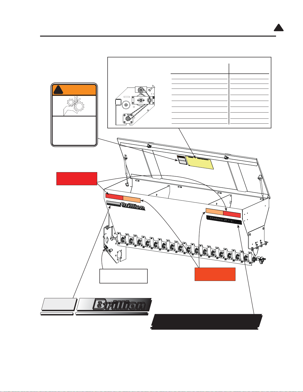
Safety Warning Decals.......................................................................................................5
Safety Decal Location- Front Seedbox ..........................................................................6, 7
Assembly/Set-up .......................................................................................................................8
Unhitching & Parking Pin ...................................................................................................8
Assembly of Options .................................................................................................................9
Lift Sling Kit........................................................................................................................9
Acre Meter Kit .............................................................................................................10-11
Operating Instructions .............................................................................................................12
Acre Meter ..................................................................................................................12-13
Seeding Rate Adjustment ...........................................................................................14-15
Seed Rate Calibration & Seed Charts .............................................................................16
Adjustment of Wheel Track Remover ..............................................................................17
Maintenance............................................................................................................................18
Lubrication .......................................................................................................................18
Roller Wheels...................................................................................................................18
Chain Tension ..................................................................................................................19
Acre Meter .......................................................................................................................19
Feed Cup Adjustment ......................................................................................................20
Adjustment Wrenches......................................................................................................21
SECTION II - ADDITION OF OPTIONAL REAR SEEDBOX
Decal Locations - Rear Seedbox ....................................................................................25
Assembly Instructions .............................................................................................................26
Rear Box End Plates........................................................................................................26
Deflector...........................................................................................................................27
Seed Box .........................................................................................................................28
Right End Seed Shaft & Bearing......................................................................................29
Transmission..............................................................................................................30, 31
Operating Instructions .............................................................................................................32
Seed Rate, Feed Cup Adjustment .............................................................................32, 33
Seed Rate Calibration & Seed Charts .............................................................................34
Chain Tension ..................................................................................................................35
Specifications ..........................................................................................................................36
Model Designations .........................................................................................................36
Dimensions ......................................................................................................................36
Optional Equipment List w/ Weights........................................................................................36
Contents
806 Page 1

1P128

1P128
To obtain maximum benefits from the Brillion Turfmaker Junior Grass Seeder, please study this manual
carefully before operating or starting assembly of optional equipment . If items covered in this manual
are not understood, contact your local Brillion dealer.
This safety alert symbol is used to call your attention to instructions concern-
ing personal safety. This symbol is found throughout this manual and will be
found on your machine. It points out important safety precautions. It means
“ATTENTION! BECOME ALERT! YOUR SAFETY IS INVOLVED!” Read the
message that follows and be alert to the possibility of personal injury or death.
!
Parts Ordering
When ordering parts for this machine, include the complete model number and serial number. Refer to
the name plate on the seedbox at the right front. Please record these numbers upon taking delivery of
the unit.
Be sure to read the warranty card which is
shipped with the machine. Return the proper
portion of the card for recording at the factory.
Location Reference
Right hand, left hand and forward designations are those related to the operator when sitting in the
operating position.
Seeder Model
Serial Number
Date Purchased
NAMEPLATE
Introduction
806 Page 3

1P128
Federal law requires that you explain the safety and operating instructions
furnished with this machine to all employees before they are allowed to op-
erate the machine. These must be repeated to the employees at the begin-
ning of each season. Be sure to observe and follow the instructions for the
safety of anyone operating or near the machine.
Investigation has shown that nearly one-third of all farm accidents are
caused by careless use of machinery. You can do your part in improving
safety by observing the following suggestions. Insist that all people working
with you or for you abide by them.
1. Do not stand between the tractor and implement when attaching or detaching implement
unless both are not moving.
2. Do not make adjustments or lubricate machine while it is in motion.
3. Do not allow anyone to ride on tractor or machine.
4. Always use transport lock when transporting machine.
5. Do not transport at speeds over 20 mph.
6. Avoid sudden stops or turns when transporting because weight of machine may cause op-
erator to lose control of tractor. Make sure tractor or towing vehicle is heavier than seeder;
be sure the front of the tractor has enough weight to maintain control when transporting a
seeder with a fully loaded seed box.
8. When transporting the machine on a road or highway, use adequate warning symbols,
reflectors, lights, and slow moving vehicle signs as required.
9. Lower machine to ground when not in use. See page 8 if unhitching tractor with machine
on the ground.
10. Block machine so it will not roll when unhitched from tractor.
12. Securely block machine when working on or under it to prevent injury in case of hydraulic
failure or inadvertent lowering by another person.
13. Be sure to engage parking pin on left side of machine before disconnecting tractor. Other-
wise machine may tip backward on frame.
14. Escaping hydraulic fluid under pressure can have sufficient force to penetrate the skin,
causing serious personal injury. Before applying pressure to the system, be sure all con-
nections are tight and that the lines and hoses are not damaged.
15. Hydraulic fluid escaping from a very small hole can be almost invisible. Use a piece of
cardboard or a piece of wood, rather than hands, to search for suspected leaks.
!
!
Safety
Safety Suggestions
806 Page 4

1P128
16. To prevent machine from tipping backward on frame, disengage parking pin only when
seeder is fully attached to tractor.
17. Keep all guards in place. Replace any that become damaged.
18. Stay clear of machine when using the lift sling to lift or move it. Do not work under ma-
chine using only the sling to support it. Keep observers away.
!
Safety
There are three levels of hazard intensity that appear with the safety alert symbol on safety decals:
DANGER, WARNING, and CAUTION. The level of hazard intensity is determined by the following
definitions:
DANGER - Immediate hazards which WILL result in severe personal injury or death.
WARNING - Hazards or unsafe practices which COULD result in severe personal
injury or death.
CAUTION - A reminder of safety practices, or directs attention to unsafe practices
which could result in personal injury.
Examine safety decals and be sure you have the correct safety decals for the machine. Keep these
signs clean so they can be observed readily. It is important to keep these decals cleaned more fre-
quently than the machine. Wash with soap and water or cleaning solution as required.
Replace decals that become damaged or lost.
Order decals through your BRILLION dealer.
When applying decals to the machine, be sure to clean the surface to remove any dirt or residue.
Where possible, sign placement should protect the sign from abrasion, damage, or obstruction from
mud, dirty oil, etc.
The safety decals for the Turfmaker Junior Seeder and their locations on the machine are pictured on
the following two pages.
!
!
!
Safety Signs
!
806 Page 5

1P128
OPEN
CLOSED
9K788
Brillion
Brillion
Turfmaker
Junior
Amber Reflective, 2” x 9”
P/N 2J431
“Brillion” Decal
P/N 4K036
“Turfmaker Junior” Decal - P/N 6K040
BE SURE TO ENGAGE
PARKING PIN ON LEFT END OF
FRAME BEFORE UNHITCHING
TRACTOR. OTHERWISE
FRAME WILL TIP BACKWARDS
ABOUT FRONT AXLE.
9J302
CAUTION
!
MOVING MACHINES CAN CAUSE INJURY. KEEP AWAY!
1. KEEP AWAY FROM MOVING TRACTORS OR IMPLEMENTS.
KEEP OTHERS AWAY.
2. DO NOT RIDE OR ALLOW OTHERS TO RIDE ON TRACTOR
OR IMPLEMENT.
3. BLOCK IMPLEMENT TO PREVENT MOVEMENT WHEN
UNHITCHED FROM TRACTOR.
4. KEEP ALL GUARDSAND SHIELDS IN PLACE WHILE MACHINE
OR PARTS ARE IN MOTION.
8J309
!CAUTION
!
Safety
Engage Parking Pin
P/N 9J302
Caution List
P/N 8J309
Cover Latch Decal
P/N 9K788
Safety Signs
806 Page 6

1P128
PARKING PIN
9J301
Seed Box May Be Calibrated for Unlisted Seed as Follows:
1. Raise machine & lock in transport position.
2. Place a tarp under machine to collect seed.
3. Turn the idler shaft counterclockwise:
232 revolutions - 6’
348 revolutions - 4’
4. Weigh seed and multiply by 10 (20 for 26-Tooth
Driver) for approximate planting rate in lbs/acre.
PLANTING RATES FOR SEED BOX
INDICATOR SETTING
POUNDS PER ACRE POUNDS PER 1000 SQ. FT.
1 2 3 4 5 6 7 8 1 2 3 4 5 6 7 8
WARNING
!
MOVING PART HAZARD
TO PREVENT SERIOUS INJURY
FROM MOVING PARTS:
• KEEP COVERS CLOSED DURING
OPERATION.
• DO NOTALLOW ANYONE TO RIDE
OR CLIMB ON MACHINE DURING
OPERATION.
•KEEP OBSERVERS AWAY. 2K123
Brillion
Brillion
Turfmaker
Junior
“Brillion” Decal
P/N 4K036
Red-Orange
P/N 8K597
Red
P/N 2J430
“Parking Pin” Decal
P/N 9J301
“Turfmaker Junior” Decal
P/N 6K040
!
Safety
Moving Parts Warning
P/N 2K123
Seed Chart
P/N 6K028
Safety Signs
806 Page 7

1P128
Assembly / Set Up
A 3-point hitch is built into the seeder frame. After attaching to the tractor, move the Parking pin to its
outside position.
CAUTION!
1. Do Not Disengage Parking Pin Unless Seeder Is Fully Attached
To Tractor. Seeder may be rear-heavy and tip backward on frame.
2. Be sure front of tractor has enough weight to maintain control when
Transporting a seeder with a fully loaded seed box.
ATTACHING TO TRACTOR
!
!
HITCH PIN
KLIK PIN
FRONT
FRONT
(USE THIS HOLE WHEN
DISCONNECTED FROM TRACTOR)
(USE THIS HOLE WHEN
CONNECTED TO TRACTOR)
PARKING PIN
KLIK PIN
Your Turfmaker Junior Seeder is preassembled at the factory. Instructions for the addition of optional
equipment can be found on the following pages.
806 Page 8

1P128
Assembly / Lift Sling & Stabilizer (Optional)
Stay clear of machine when using the lift sling to lift or move it.
Do not work under machine using only the sling to support it.
Keep observers away.
Lift Sling Kit (Optional)
1. Locate the mounting bracket on the left side of machine and mounting bracket and strap on the
right side of machine. They are attached at the center holes of the right and left end plates.
2. Attach lift sling to mounting brackets with 5/8” x 1 1/2” capscrews and stover nuts provided in kit.
3. Slide stablizer into frame tube and secure with clevis pin and hairpin cotter.
HHCS, 5/8 x 1 1/2”
HHCS, 5/8 x 1 1/2”
LOCK NUT, 5/8
MOUNT
BRACKET
LOCK NUT, 5/8
MOUNT
BRACKET
STRAP LEFT END PLATE
HAIRPIN
CLEVIS
PIN
STABILIZER
806 Page 9

1P128
for models:
SLP204, -206; SLP2041, -2061;
LSP5, -6; LSS6
Installation:
The acre meter consists
of three main parts; the
acre meter, the pick-up,
and the magnet wheel.
1. Use the acre meter
bracket as a guide
and drill two 13/32”
holes into seedbox at
location shown in
illustration. Then
attach the acre meter
bracket as shown with
two 3/8-16 x 1”
capscrews,
lock washers
and nuts.
2. Unlatch and swing open the
transmission guard shield on the left side of
the machine. (Be sure to re-close and latch
securely when you have finished acre meter
installation).
Remove the bottom rear capscrew from the
transmission bracket and use this hardware
(5/16 x 1” capscrews, lock washers and nuts)
to attach the 6K447 pick up switch bracket.
Install it on the rear inside surface of the left
side frame end plate. Do not tighten screws
at this time.
ACRE METER
BRACKET
HHCS, 3/8-16 X 1”
LOCK WASHER, 3/8
NUT, 3/8-16
ACRE METER
ASSEMBLY
6K447 PICK UP
SWITCH BRACKET
PICK UP
SWITCH
TRANSMISSION
GUARD SHIELD
TRANSMISSION
BRACKET
HHCS, 5/16-18 X 1”
LOCK WASHER, 5/16
NUT, 5/16-18
Assembly / Acre Meter Kit 6K036
(Optional)
806 Page 10

1P128
5. Adjust the pick up switch and bracket so
the center line of magnet wheel and pick
up switch are horizontally and vertically
aligned with a maximum 1/8” between mag-
net wheel and pick up switch. Now firmly
tighten all screws.
6. Attach the short pick up switch ground wire
to the small hole in the 6K447 bracket with
a #6-32 x 1/2” machine screw, removing
paint under the wire connector to assure a
good electrical ground connection.
7. Route the wire from the acre meter down the front of the seed box and
around the outsideof the end bracket to the pick up switch and connect
the mating plugs.
8. Securely fasten the wire to seed box and end bracket using the adhesive
mounting bases and wire ties to prevent wire from becoming entangled or
rubbing moving parts.
9. Program acre counter following the instructions on the next page.
Note: Alignment of pickup switch
and magnet wheel is critical.
Improper alignment will
cause the acre counter to
record acres erratically or
not at all.
Side View
Top View
3. Attach the pick up switch to the top of the
6K447 bracket with two #8-32 x 1 1/4”
machine screws, flat washers, lock wash-
ers, and nuts. Do not tighten screws at this
time.
1/8”
Maximum
MAGNET WHEEL
PICK UP
SWITCH
MACHINE SCREW,
#8-32 X 1 1/4”
FLAT WASHER, #8
LOCK WASHER, #8
NUT, #8-32
HHCS, 5/16-18 X 1”
LOCK WASHER, 5/16
NUT, 5/16-18
4. Press the magnet wheel onto the idler
shaft until it is vertically centered with
pick up switch.
PICK UP
SWITCH
6K447PICK UP
SWITCH BRACKET
MACHINE SCREW,
#6-32 x 1/2”
NUT, #6-32
GROUND
WIRE
Assembly / Acre Meter Kit
806 Page 11

1P128
ELECTRONIC ACRE METER
- QUICK-START SETTINGS
SPECIAL NOTES
• When meter is set to “count” mode in pulses screen, meter will register only magnetic wheel
revolutions.
• Meter must be in sleep mode (blank screen) to calculate acres or to count pulses.
• Count screen must have a value other than zero (0000) to scroll to other modes or screens.
• To reset FIELD ACRES screen to zero (0000), press the up and down buttons simultaneously.
MODEL PULSES PULSES
PER ACRE PER1000 sq.’ WIDTH
SSPT604 293 67 5
SSP8 SS8 764 18 8
SSP10 SS10 764 18 10
SSP12 SS12 764 18 12
SSP108 SS108 760 17 8
SSP110 SS110 760 17 10
SSP112 SS112 760 17 12
SSP208 SSP2081 SS208 SS2081 764 18 8
SSP210 SSP2101 SS210 SS2101 764 18 10
SSP212 SSP2121 SS212 SS2121 764 18 12
SSP308 SS308 764 18 8
SSP310 SS310 764 18 10
SSP312 SS312 764 18 12
GLP643 SSLP643 917 21 5
SLP10 SL10 4147 95 10
SLP12 SL12 4147 95 12
SLP204 1690 39 4
SLP206 1690 39 6
SLP304 845 19 4
SLP306 845 19 6
LSP5 1690 39 5
LSP6 1690 39 6
LSS6 1690 39 6
SLP208 SL208 1528 35 8
SLP210 SL210 1528 35 10
SLP212 SL212 1528 35 12
SLP308 SL308 1528 35 8
SLP310 SL310 1528 35 10
SLP312 SL312 1528 35 12
BOS4S BOS4F BOSB4S BOSB4F 600 14 4
BOS6S BOS6F BOSB6S BOSB6F 600 14 6
Operating Instructions/ Acre Meter
806 Page 12

1P128
TO PROGRAM METER
1. Press function button to scroll to pulses screen.
2. Enter the number of pulses for the model as listed on page 2 using the up or down but-
tons.
3. Press function button to set pulses. (If screen goes blank before you press the function
button, repeat steps 1 & 2).
4. Press function button to scroll to width screen.
5. Enter the width of seeder for the model as listed on page 2 using the up or down buttons.
6. Press the function button to set width. (If screen goes blank before you press the function
button, repeat steps 4 & 5).
7. Press function to scroll through screens to check that the correct pulses and width have
been entered.
TO ENTER PASSWORD
1. Press function button to scroll to pass screen.
2. Pick a number and enter it by using the up or down buttons.
3. Press function button to set password; number screen will show (set): Record number - it
is required if you need to disable password.
4. Let screen go blank - password is now entered.
TO DISABLE PASSWORD
1. Press function button to scroll to pass screen - will show (ent).
2. Use up or down button to enter password (number).
3. Press function button to scroll around to pass screen again. Number entered in step 2 will
appear.
4. Press up or down button to enter 0.
5. Press function button; (dis) will appear. Password is now disabled.
Operating Instructions/ Acre Meter
806 Page 13

1P128
To increase the rate of seeding, loosen the nut on inside of
the bearing and turn the outer nut to move the seed shaft to
the desired higher number setting, then re-tighten the
inner nut.
To decrease the rate of seeding, loosen the outer nut
and turn the inner nut to move the seed shaft to the
desired lower number position; then re-tighten the
outer nut.
Seed cups discharge to the front of the
machine to aid the tractor driver in
determining proper operation.
Seed Rate Adjustment
Note: Wrenches for adjustment are stored on a rivet on the right-side end plate. (See Figure11)
IMPORTANT: To prevent damage to seed meters, do not apply excessive force to adjusting
nuts. This is especially important when closing meters as seed in flutes can be
pinched between cut -off and washer in seed cup. Do not attempt to open meters
more than 1”. (Feed rolls could become disengaged from washer in seed cup.)
Seed rate is set by adjusting the micro-meter on the right side of the machine.
Note: Before you begin, be sure pointer
reads “0” when cups are complety closed .
Increase:
shaft moves this direction
Decrease:
shaft moves this direction
VIEW FROM
FRONT
FRONT OF
MACHINE
Adjust pointer
position here.
OUTER
ADJUSTING
NUT
INNER
ADJUSTING
NUT
POINTER
Operating Instructions/ Seeding Rate
806 Page 14

1P128
DRIVE CHAIN SET FOR
13-TOOTH SEED RATE
REMOVE
26-TOOTH
SPROCKET
ADD EXTRA
LINKS
REMOVE 1/4”
ROLL PIN
CHANGE
SPROCKET &
REPLACE 1/4”
ROLL PIN
STORE
13-TOOTH
SPROCKET
3/4” NUT
3/4” NUT
Seed rates can be doubled by using the 26-tooth sprocket and extra chain links included with the
seeder.
Procedure is as follows:
1. Loosen drive chain as shown on page 19 (Chain Tension)
2. Open chain at connector.
3. Remove 1/4” roll pin in 13- tooth sprocket and 3/4” nut on 26-tooth sprocket.
4. Exchange sprockets to new positions and replace roll pin and nut.
5. Add extra chain links as provided with this seeder.
6. Adjust chain tension as shown on page 19.
Operating Instructions/ Seeding Rate
DRIVE CHAIN SET FOR
26-TOOTH SEED RATE
806 Page 15

1P128
Operating Instructions/ Seeding Rate
Seed Rate Calibration
•Seed rate charts are located inside the seed box covers of both the front and rear seed boxes. They should be used
as general guides only. Because of seed variation, a more accurate rate can be found by calibrating the seeder as
shown in steps 1-6.
•The provided charts were determined by laboratory tests on various samples. To find rates for specific seed lots or
to calibrate for unlisted seeds, proceed as shown on the seed charts reproduced below and on the next page.
Calibration of Front Seed Box
Front Seed Box May be calibrated for unlisted seed as follows:
1. Raise Machine and Lock in transport position.
2. Place a tarp under machine to collect seed.
3. Turn 1/2-13 Capscrew on the Idler 13-Tooth Sprocket Counter-clockwise as follows:
•232 revolutions for 6-foot seeder
•348 revolutions for 4-foot seeder
4. Weigh seed and multiply by 10 (20 for 26 tooth driver) for approximate planting rate in pounds/acre.
1. Rates are for 13 tooth driver. Double these values for 26 tooth driver.
2. Rates are intended as a guide only. Variation in size and cleanliness will affect rates.
Check acreage and pounds of seed used for best results.
PLANTING RATES FOR FRONT SEED BOX
IDLER WITH
3/4” HEX
37 TOOTH
DRIVEN
13 TOOTH
DRIVER (USING THE 26 TOOTH
SPROCKET DOUBLES THE
SEED RATES SHOWN)
6K028
806rev6-25-08 Page 16
INDICATOR SETTING 12345678 1 2345678
ALFALFA 32 78 164 259 361 486 595 699 0.73 1.79 3.77 5.95 8.29 11.15 13.67 16.04
BAHIA 24 70 157 251 322 384 486 549 0.55 1.61 3.61 5.77 7.38 8.81 11.15 12.61
BARLEY 8 78 180 274 376 463 557 659 0.18 1.79 4.13 6.29 8.63 10.63 12.79 15.13
BENT 16 40 78 142 228 282 329 415 0.36 0.91 1.79 3.25 5.22 6.47 7.56 9.54
BERMUDA 32 94 157 233 376 533 635 785 0.73 2.16 3.61 5.35 8.63 12.24 14.58 18.01
BIRDSFOOT TREFOIL 32 86 164 282 384 501 635 745 0.73 1.97 3.77 6.47 8.81 11.51 14.58 17.10
BLUE GRASS (KENTUCKY) 24 45 85 155 208 259 339 389 0.55 1.03 1.94 3.55 4.77 5.95 7.78 8.93
BUFFALO GRASS - 8 40 78 110 134 150 188 - 0.18 0.91 1.79 2.52 3.07 3.43 4.31
CANOLA 32 94 180 274 384 471 557 619 0.73 2.16 4.13 6.29 8.81 10.81 12.79 14.22
CENTIPEDE 32 78 150 282 447 565 699 777 0.73 1.79 3.43 6.47 10.27 12.97 16.04 17.83
CHICKORY 28 66 122 189 262 335 405 475 0.64 1.52 2.79 4.34 6.01 7.68 9.29 10.90
CLOVER, ALSIKE 32 78 180 314 439 565 699 785 0.73 1.79 4.13 7.20 10.08 12.97 16.04 18.01
CLOVER, RED 48 102 172 243 306 392 463 517 1.09 2.34 3.95 5.59 7.02 8.99 10.63 11.88
FESCUE (CREEPING RED) 8 24 62 126 164 204 243 259 0.18 0.55 1.43 2.89 3.77 4.68 5.59 5.95
FESCUE (TALL) 24 45 95 161 254 310 381 463 0.55 1.03 2.19 3.71 5.83 7.11 8.75 10.63
LESPEDEZA (HULLED) 40 110 228 369 557 667 785 910 0.91 2.52 5.22 8.47 12.79 15.31 18.01 20.90
LESPEDEZA (UNHULLED) 16 54 102 188 259 314 376 447 0.36 1.25 2.34 4.31 5.95 7.20 8.63 10.27
LOVE GRASS 48 110 251 392 525 635 769 894 1.09 2.52 5.77 8.99 12.06 14.58 17.65 20.53
MILLET 24 48 157 259 353 439 517 603 0.55 1.09 3.61 5.95 8.11 10.08 11.88 13.85
MILO 62 150 236 329 447 541 603 721 1.43 3.43 5.41 7.56 10.27 112.42 13.85 16.55
NEEDLE GRASS 8 40 118 204 298 384 494 557 0.18 0.91 2.70 4.68 6.83 8.81 11.33 12.79
OATS 40 78 134 180 259 306 345 400 0.91 1.79 3.07 4.13 5.95 7.02 7.93 9.17
ORCHARD GRASS 8 16 32 70 118 134 157 172 0.18 0.36 0.73 1.61 2.70 3.07 3.61 3.95
RYE GRASS 16 48 110 172 236 298 353 408 0.36 1.09 2.52 3.95 5.41 6.83 8.11 9.36
SUDAN 16 86 188 298 408 533 659 769 0.36 1.97 4.31 6.83 9.36 12.24 15.13 17.65
SWITCH GRASS 48 120 210 306 402 500 597 695 1.09 2.76 4.83 7.02 9.23 11.48 13.70 15.95
TIMOTHY 24 62 172 282 376 494 557 651 0.55 1.43 3.95 6.47 8.63 11.33 12.79 14.94
TURNIP 42 107 193 286 378 471 565 695 0.97 2.46 4.43 6.56 8.69 10.81 12.97 15.95
VETCH 16 94 196 290 392 486 589 675 0.36 2.16 4.50 6.65 8.99 11.15 13.52 15.49
WESTERN WHEAT GRASS 1 16 54 110 157 204 228 274 0.03 0.36 1.25 2.52 3.61 4.68 5.22 6.29
WINTER WHEAT 70 142 243 345 439 541 627 705 1.61 3.25 5.59 7.93 10.08 12.42 14.40 16.19
Pounds per Acre Pounds per Sq. Feet

1P128
Adjustment of Wheel Track Remover
The depth of the wheel track removers can be
adjusted as shown. Loosen the (4) 1/2” capscrews
and nuts that secure the clamps to the coil tine
supports. Adjust the supports up or down to the
desired depth and then retighten the nuts on the
screws. Do this for each pipe and tine assembly.
CAPSCREW
1/2-13 NC x 1 1/2”
Operating Instructions/ Depth Adjustment
806 Page 17

1P128
Roller Wheels
Occasionally it is necessary to loosen clamp
bands and tighten roller wheel assemblies.
As nearly as possible, peaks on rear wheels
should line up with valleys on front wheels.
This requires adjusting both end clamps on
the rear axle drum.
Maintenance
Lubrication
Grease all fittings every 20 hours.
Each of the four flangette bearings
supporting the rollers has a grease
fitting.
FRONT
ROLLERS
AXLE CLAMPS
REAR
ROLLERS
Oil roller chains periodically.
20
HRS.
(both R & L
sides)
806 Page 18
This manual suits for next models
3
Table of contents
Other Brillion Seeder manuals
Popular Seeder manuals by other brands

Maschio
Maschio Gaspardo SP Series Use and maintenance

Earth Way
Earth Way 1001-B PRECISION Assembly and operating instructions

Gearmore
Gearmore PTB560 Assembly manual

Seederman
Seederman GS2 Owners Manual and Operating Guide

Land Pride
Land Pride 313-308M Operator's manual

LELY
LELY LOTUS 460 Stabilo Operator's manual