Brillion SS-10 Operation and maintenance manual

ASSEMBLY
INSTRUCTIONS
OPERATOR'S
MANUAL
SURE
STAND
GRASS
SEEDER
qqs
l\JJ
.....
FEMA
MODEL
SS-10
BRILLION
IRON
WORKS,
INC.
BRILLION, WISCONSIN 54110 9J467

CONTENTS
Introduction . . . . . . . . . . . . . . . . . . . . . . . . . . . . . . . . . . . . . . . . . . . . . . . . . . . . . . . . . 3
Location Reference . . . . . . . . . . . . . . . . . . . . . . . . . . . . . . . . . . . . . . . . . . . . . . . . . 3
Parts Ordering . . . . . . . . . . . . . . . . . . . . . . . . . . . . . . . . . . . . . . . . . . . . . . . . . . . . 3
Safety Suggestions . . . . . . . . . . . . . . . . . . . . . . . . . . . . . . . . . . . . . . . . . . . . . . . . . . . . 4
Safety Decals . . . . . . . . . . . . . . . . . . . . . . . . . . . . . . . . . . . . . . . . . . . . . . . . . . . .
4A
Operating Instructions . . . . . . . . . . . . . . . . . . . . . . . . . . . . . . . . . . . . . . . . . . . . . . . . . . 5
Transport Lock . . . . . . . . . . . . . . . . . . . . . . . . . . . . . . . . . . . . . . . . . . . . . . . . . . . 5
Parking Pin . . . . . . . . . . . . . . . . . . . . . . . . . . . . . . . . . . . . . . . . . . . . . . . . . . . . . . 5
Meter
Box
Seed Rate . . . . . . . . . . . . . . . . . . . . . . . . . . . . . . . . . . . . . . . . . . . . . . . 6
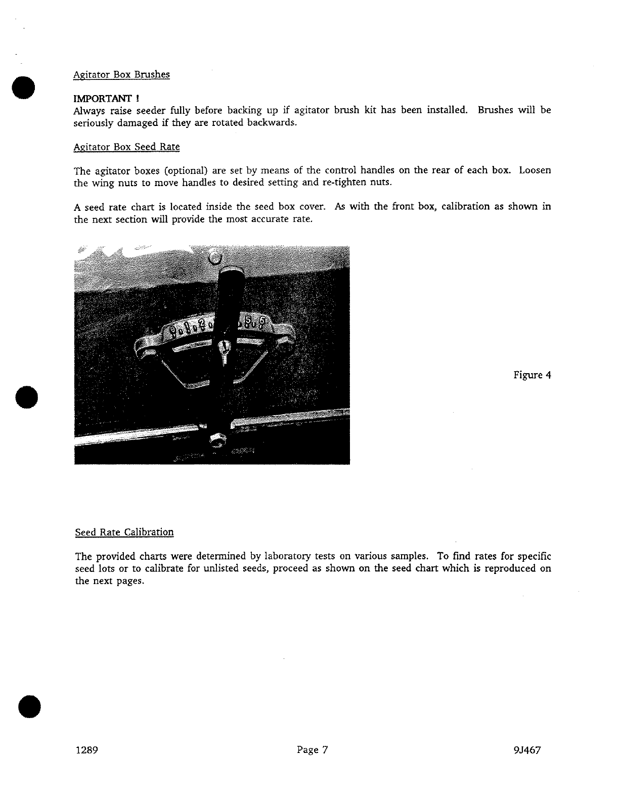
Agitator
Box
Brushes . . . . . . . . . . . . . . . . . . . . . . . . . . . . . . . . . . . . . . . . . . . . . . . 7
Agitator
Box
Seed Rate . . . . . . . . . . . . . . . . . . . . . . . . . . . . . . . . . . . . . . . . . . . . . . 7
Seed Rate Calibration . . . . . . . . . . . . . . . . . . . . . . . . . . . . . . . . . . . . . . . . . . . . . . . 7
Seed Chart for Meter
Box
. . . . . . . . . . . . . . . . . . . . . . . . . . . . . . . . . . . . . . . . . . . . 9
Seed Chart for Agitator
Box
. . . . . . . . . . . . . . . . . . . . . . . . . . . . . . . . . . . . . . . . .
10
Transmission Drive Bolt . . . . . . . . . . . . . . . . . . . . . . . . . . . . . . . . . . . . . . . . . . . .
11
S-Tine Tire Track Remover (optional) . . . . . . . . . . . . . . . . . . . . . . . . . . . . . . . . . . .
11
Coil Tine Track Remover (optional) . . . . . . . . . . . . . . . . . . . . . . . . . . . . . . . . . . . . 11
Maintenance . . . . . . . . . . . . . . . . . . . . . . . . . . . . . . . . . . . . . . . . . . . . . . . . . . . . . . .
12
Acre Meter . . . . . . . . . . . . . . . . . . . . . . . . . . . . . . . . . . . . . . . . . . . . . . . . . . . . . 12
Fasteners . . . . . . . . . . . . . . . . . . . . . . . . . . . . . . . . . . . . . . . . . . . . . . . . . . . . . . 12
Lubrication . . . . . . . . . . . . . . . . . . . . . . . . . . . . . . . . . . . . . . . . . . . . . . . . . . . . .
12
Tires
.........................................................
12
Chain Tension . . . . . . . . . . . . . . . . . . . . . . . . . . . . . . . . . . . . . . . . . . . . . . . . . . . 13
Roller Wheels . . . . . . . . . . . . . . . . . . . . . . . . . . . . . . . . . . . . . . . . . . . . . . . . . . .
14
Feed Cup Adjustment . . . . . . . . . . . . . . . . . . . . . . . . . . . . . . . . . . . . . . . . . . . . . . 14
Agitator
Box
Slide . . . . . . . . . . . . . . . . . . . . . . . . . . . . . . . . . . . . . . . . . . . . . . . . 15
Assembly Instructions . . . . . . . . . . . . . . . . . . . . . . . . . . . . . . . . . . . . . . . . . . . . . . . . .
16
Pull Type Seeder . . . . . . . . . . . . . . . . . . . . . . . . . . . . . . . . . . . . . . . . . . . . . . . . . 16
Pick-Up Seeder . . . . . . . . . . . . . . . . . . . . . . . . . . . . . . . . . . . . . . . . . . . . . . . . . .
16
Agitator
Box
(optional)
...........................................
17,18'
Tire Track Remover (optional) . . . . . . . . . . . . . . . . . . . . . . . . . . . . . . . . . . . . . . . .
19
Acre Meter (optional) . . . . . . . . . . . . . . . . . . . . . . . . . . . . . . . . . . . . . . . . . . . . . .
19
Meter
Box
Dividers (optional) . . . . . . . . . . . . . . . . . . . . . . . . . . . . . . . . . . . . . . . .
20
Speed-Up
Kit
(optional) . . . . . . . . . . . . . . . . . . . . . . . . . . . . . . . . . . . . . . . . . . . .
21
Brush Agitator Kit (optional) . . . . . . . . . . . . . . . . . . . . . . . . . . . . . . . . . . . . . . . . .
21
Coil Tine Tire Track Remover (optional) . . . . . . . . . . . . . . . . . . . . . . . . . . . . . . . . . 22
Scraper
Kit
(optional) . . . . . . . . . . . . . . . . . . . . . . . . . . . . . . . . . . . . . . . . . . . . . . 23
Safety Chain
Kit
-
10,100#
(optional)
...................................•
24
Specifications . . . . . . . . . . . . . . . . . . . . . . . . . . . . . . . . . . . . . . . . . . . . . . . . . . . . . . . 25
Model Designations . . . . . . . . . . . . . . . . . . . . . . . . . . . . . . . . . . . . . . . . . . . . . . . 25
Weights and Dimensions . . . . . . . . . . . . . . . . . . . . . . . . . . . . . . . . . . . . . . . . . . . . 25
Optional Equipment
.............................
.".
. . . . . . . . . . . . . . . . . . . 26
1292 Page 2 9J467

INTRODUCTION
To obtain maximum benefits from the Brillion Grass Seeder, please study this manual carefully before
starting assembly or operation. A special section, "Assembly Instructions",
is
included. If items covered
in this manual are not understood, contact your local Brillion dealer
or
call Brillion Iron Works, Inc.
at
414/756-2121.
This safety alert symbol
is
used to call your attention to instructions concerning personal
safety. This symbol
is
found throughout this manual and will be found on your machine.
It points out important safety precautions. It means 'ATTENTION!
BECOME
ALERT!
YOUR
SAFETY
IS
INVOLVED!'
Read the message
that
follows
and
be alert to the
possibility of personal injury
or
death.
Location Reference
Right hand, left hand and forward designations are those related to the operator
when
sitting in the
operating position.
Parts Ordering
When ordering parts for this machine, include the complete model number and serial number. Refer to
the name plate on the right end, front surface, of the seed
box.
Please record these numbers upon taking
delivery of the unit.
Seeder Model
Serial Number
Date Purchased
Be
sure to read the warranty card which
is
shipped with the machine. Return the proper portion
of
the
card for recording
at
the factory.
1292.
NAME
PLATE
LOCATION
Page 3 9J467

•
SAFETY
SUGGESTIONS
Federal law requires you to explain the safety
and
operating instructions furnished with this machine to
all employees before they are allowed to operate the machine. These must
be
repeated to the employees
at
the
beginning
of
each season.
Be
sure to observe
and
follow the instructions for the safety of anyone
operating
or
near
the machine.
Investigation has
shown
that
nearly one-third of all farm accidents are caused by careless use of
machinery. You
can
do your
part
in improving safety by observing the following suggestions. Insist
that
all people working with you or for you abide by them.
1.
Do
not
stand
berween the tractor and implement when attaching or detaching implement unless both
are not moving.
2.
Do
not make adjustments
or
lubricate machine while
it
is
in motion.
3.
Do
not
allow anyone to ride on tractor or machine.
4. Always use
transport
lock when transporting machine.
5.
Do
not
transport
at
speeds over 20 mph.
6.
Avoid
sudden
stops
or
turns when transporting because weight of machine may cause operator to Jose
control of tractor. Use a tractor heavier
than
machine.
Do
not
allow tractor drawbar to swing
when
transporting.
7.
Use
caution when towing behind articulated steering tractors; fast or sharp turns may cause the
machine to slip sideways.
8. When transporting the machine on a road or highway, use adequate warning symbols, reflectors,
lights, and slow moving vehicle signs
as
required.
9.
Lower machine to ground when not
in
use.
10. Block machine so it will
not
roll when unhitched from tractor.
11. Relieve pressure in hydraulic lines before uncoupling hydraulic hoses from tractor. On most tractors
this can be done by operating valves after engine
is
stopped.
12. Securely block machine when working on or
under
it to prevent injury in case of hydraulic failure
or inadvertent lowering by another person.
13.
Be
sure to engage parking pin on left side of pick-up models
bet"ore
disconnecting tractor. Otherwise
machine may tip backward on frame. ·
14. Install safety chain berween the pull type seeder and the tractor. See page
24
of this manual,
and/or
see tractor manual.
15. Escaping hydraulic fluid under pressure can have sufficient force to penetrate the skin, causing serious
personal injury. Before applying pressure to the system, be sure all connections are tight
and
that
lines
and
hoses are not damaged.
16. Hydraulic fluid escaping from a very small hole can be almost invisible. Use a piece
of
cardboard
or
a piece
of
wood, rather than hands, to search for suspected leaks.
1292 Page 4 9J467 •

Safety Decals
There are three levels
of
hazard intensity that appear with the safety alert symbol on safety decals:
DANGER,
WARNING, and CAUTION. The level
of
hazard intensity is determined by the following definitions:
DANGER -Immediate hazards which
Will
result in severe personal injury
or
death.
WARt<ING
-Jii\zards
or
unsafe practices which COULD result in severe personal injury
or
death.
·,
,,
~
·7
~~-.'
. '
CAOTION
-A~i{niinder
of
safety practices,
or
directs attention
to
unsafe practices which could result
in
personal
" injury.
Examine safety decals.
and
be
sure
you
have the correct safety decals for the mafhine. Keep these signs clean so
they can
be
observed readily. It is iniportant to keep these ·decals cleaned more frequently than the machine.
. . Wash with soap and water
or
cleaning solution
as
required.
Replace decals
that
become damaged
or
lost.
1
9}aer
decals through
y~~r
BRIILION dealer.
:.
'.::,'t,
.
\Ir
-....,
.
'When
applying decals to the machine, be sure to clean the surface to remove any dirt
or
residue. Where possible,
.'Sign
placement should protect the sign from abrasion, damage,
or
obstruction from mud, dirty oil, etc.
These are the safety decals provided for the seeder. (Refer to repair parts catalog for more information on the
location
of
each safety sign on the equipment).
~~
3K706-DRAWBAR
HOVlNG
PART
HAZARD
2Kl23-1NSJOE
SEEDBOXES
10
Pfl£VlN1
S,ElllOUS
IHJUl!l
FROl1
I
nOVIMG
PAR1S1
•!CUP
COY~
d115£D-
DURING
llPutAlJON.
l
l!I
MQ1
Al.Liii
Mi'flflll
10 IUDt
111
Cllnl
IH
llACMlNl
WIUNG
OP£AATtOH.
9J302-TOP
OF
THREE
POINT
HITCH
(PICK-UP
MODELS
ONLYl
lllf
DBSlRVUlS
AVAl.
·
.
211"12'3
·-
BJ309-LEFT
FRONT
SEEDBOX
&
CAUTION
JMOVING
MACHINES
CAN
CAUSE
INJURY.
KEEP
AWAYI
I
l.
DO
NOT
STAND
OR
WALK
IN
FRONT
OF
TRACTOR
WHEN
I l1
1S
MOVING
FORWARI).
. 2.
DO
~D1
STAND
OR
WALK
BETWEEN
TRACTOR
l
IMPLEMENT
995
WHEN-~lTHER
OR
BOTH
ARE
MOVING.
3.
DO
NOT.,:l'lJAND
OR
WALK
BEHIND
JMPLEMENT
WHEN
IT
JS
BEING
8)\CKED
UP.
4.
DP
NOT
RJOE
OR
ALLOW
OTHERS
TO
RlDE
ON
TRACTOR.
OR
JMPLEMENT.
5.
BLOCK
IMPLEMENT
TO
PREVENT
MOVEMENT
WHEN
UNHITCH
ED
FR
OM
TRACTOR._
e.no•
Page 4A
DO
NOT
GO
NEAR
LEAKS
M19h
prli•••r•
111 111117
f'V••l•r••
1•11
lllll"f
lltlMI
UJllrJ•
•..
,,
...
··~·
.......
.
u
l•J•t••·
.........
,
....
,
....
1
••
1
~
•.
1,. 1
.........
....
,...
,.
h
r•41•lrelll
f1
re••"•
•I
I.
Io•
•••••••••
,.,
••
,
·•1•
t.
........
,
'·····
t
•••
, 1
.....
, ...
11.,
•
..
,
..
,
••
,
••
,,
••••
,.
~.1
....
1
......
,
..
,
''"'"''
.
1001~
~
CAUTION
BE
SURE
TO
ENGAGE
PARK·
ING
PlN
ON
LEFT
ENO
OF
FRAHE
BEFORE
UNHITCH·
lNG
TRACTOR.
OTHER·
WlSE
FRAHE
Wlll
TlP
BACKWARDS
ABOUT
FRONT
AXLE.
'lJ302
9J467

DECAL
LOCATIONS
FOR
MODELS
WITH
BRUSH
AGITATOR
FRONT
VIEW
0
NJ.JIM!.
A$5£11.,tl0.
,,uiti.).
,,,.,_.
~·-
I
2
3
4
5
6
7
8
9
10
NOTE:
2J430
DECAL.
RED
2J431
OE
CAL.
AMBER
8J309
DECAL.
CAUTION
IKl74
DECAL.
BRILLION
9J429
DECAL.
AMBER
CSHAFTSl
9J432
DECAL.
SEED
CHART
2Kl23
DECAL.
WARNING
9J424
DECAL.
SEED
CHART
50505
DECAL.
"IMPORT
ANT"
3K706
·
DECAL.
HYDRAULIC
LEAKS
ITEMS
I 6 4 I
IN
REAR
VIEWJ
ARE
USED
ONLY
ON
REAR
BOX
WHEN
MACHINE
JS
ASSEMBLED
4
2
I
3
2
I
4
I
! ,
AT
FACTORY.
EXTRA
DECALS
ARE
PROV
I
OED
JN
DECAL
PACKAGE
FOR
ALL
FOUR
BOXES
REAR
BOX
COVERS
.(
I
NS
IDE)
L
<REAR
VIEWl.
IF
NEEDED.
ITEMS
8 6
'l
ARE
. . .
_·
_1_N_c_Lu_o_E_D~ON~M-OD_E_L_s_w_I_T_H_B_R_u_sH~A-G_1T_A_T_o~R~K-l-TS~O-N_L_Y·~~~~~~~~~~~~~~
995
Page
4B
91467

•
•
•
OPERATING
INSTRUCTIONS
Transport Lock (Pull Type Seeders Only)
To prepare machine for transport, raise it fully and pin transport lock
in
place on each lift cylinder. For
field operation, disengage each transport lock
and
replace pin.
(If
pin
is
not
installed,
transport
lock
may
bounce
up
and
break
hydraulic fittings).
Figure 1
GREASE
ZERKS
Parking Pin (Pick-Up Seeders Only)
A To prevent machine from tipping backward on frame, disengage parking
pin
only
when
seeder is fully attached to tractor.
Be
sure to observe the following sequence:
When hooking
up
seeders:
1. Attach tractor.
2. Remove klik pin, pull parking
pin
in outer position, replace klik pin.
When unhooking seeder:
1.
Remove klik pin, push in parking pin, replace klik pin.
2. Disconnect tractor.
1289 Page 5 9J467

Figure 2
Meter Box Seed Rate
Seed rate for the front or meter box
is
set by adjusting the micro-meter on the right side. To increase the
rate of seeding, loosen the large locknut on inside of the bearing and turn the seed rate adjusting
nut
to
•
the desired setting. To decrease the rate of seeding, loosen the seed rate adjusting
nut
and
set it to the •
new desired position; then tighten the large locknut.
Figure 3
A seed rate chart
is
located inside the seed box cover. It should be used as a general guide only. Because
of seed variation, a more accurate rate can be found by calibrating the seeder as shown on the
chan
and
in later pages of this manual.
Seed cups discharge to the front of the machine to aid the tractor driver in determining proper operation. •
In addition, reflective amber decals are placed on the seed shaft to indicate rotation.
1289 Page 6 9J467

•
•
•
Agitator Box Brushes
IMPORTANT!
Always raise
seeder
fully before backing
up
if
agitator brush kit has been installed. Brushes will
be
seriously
damaged
if
they are rotated backwards.
Agitator Box Seed Rate
The agitator boxes (optional) are set by
means
of
the
control handles on the
rear
of
each
box. Loosen
the
wing
nuts
to move handles to desired setting
and
re-tighten nuts.
A seed
rate
chart
is
located inside the seed box cover. As with
the
front box, calibration as
shown
in
the
next
section will provide the most accurate rate.
Figure 4
Seed Rate Calibration
The provided charts were determined by laboratory tests
on
various samples. To find rates for specific
seed lots
or
to calibrate for unlisted seeds, proceed as
shown
on
the seed
chart
which
is
reproduced
on
the next pages.
1289
Page 7
9J467

Figure 5
Using
the
standard
13
tooth
driver
sprocket,
the
seed
shaft
on
the
feed
cups
makes 200
revolutions
per
acre.
This
is
also
the
speed
of
the
15/16
11
hex on
the
outside
of
the
transmission.
(A 26
tooth
driver
sprocket
will
double
the
speed).
If
you do
not
want
to
turn
the
shaft
200
times
for
calibration,
divide
200
by
some
convenient
number and
then
multiply
the
weighed
seed
by
that
same number.
For
example,
if
you make
20
turns,
multiply
weight
by
10.
1090
Page 8 9J467
•
•
•

• • •
°'
'e.
CALIBRATION
PLANTING
RATES
FOR
SEED
METER
(FRONT
BOX
l
lWPOUNDS
PER
ACRE
MACHINE
MAY
BE
CALIBRATED
FOR
UNLISTED
SEED
AS
FOLLOWS1
I,
RATES
ARE
FOR
13
TOOTH
DRIVER.
DOUBLE
THESE
VALUES
FOR
26
TOOTH
DRIVER.
I.
REMOVE
DRIVE
BOLT
NEAR
13
TOOTH
COR
OPTIONAL
26
TOOTH)
2.
RATES
ARE
INTEN!ll'D
AS
A
GUiDE
ONLY.
VARIATIONS
IN
SIZE
AND
CLEANLINESS
WILL
AFFECT
RATES.
DRIVER
SPROCKET.
Cl!ECK
ACREAGE
AND
POUNDS
OF
SEEO
USEO
FOR
BEST
RESULTS.
2.
RAISE
MACHINE
AND
LOCK
IN
TRANSPORT
POSITION.
INDICATOR
SETTING
IA
2A
3A
..
'4-A
SA
6A
7A
a"
3.
PLACE
A
CANVAS
OR
TARP
TO
CATCH
SEED.
ALFALFA
CUNCOATEOl
2 s 9
13
I6
20
2+
27
f.
TURN
15/16
HEX
ON
TRANSMISSION
SHAFT
200
RtVOLUTIONS
BAHJA
I ' 7
10 13 16 19
21
CLOCKWISE
C<OO
IF
26
TOOTH
DRIVER
IS
USEDl.
FORTY
TURNS
BERMUDA
(HULLED)
2 5 9 If
17
21
2•
28
MAY
BE
USED
lF
RESULTS
_ARE
ADJUSTED
AS
SHOWN
IN
STEP
5.
BIRDSFOOT
TREFOIL
CBROADLEAFJ
2 6
10
I+
21
2S
31
36
5.
WEIGH
SEED
FOR
APPROXIMATE
PLANTING
RATE;
MULTIPLY
BLUE
GRASS
(
KENTUCKYl
I 2 3 s 6 B 9
10
lJElGHT
BY
5 {
10
FOR
26
TOOTH
·DRIVER)
IF
ONLY
'40
TURNS
BLUE
GRASS
CPARK
KENTUCKY)
I 3 5 B
10
13
15
17
WERE
USED.
BLUE
GRASS
(SHERMAN
BIG) I 3 ' 5 6 7 B
CAN
DLA
I•
S•
B
12
15
18
21
25
TIGHTN£R
CENTIPEDE
2 5 6 9
12
1+
16 18
CLOVER
(ALSlKE.
LA01NO,
SWEET.
RED>
2 6 9
13
17
21
2<
28
CLOVER
CALYCE.
CALIF.
BUR
.•
CRIMSON,
HUBAM)
2 5 B
12 17
20
2<
30
~
I
~
CRESTED
WHEAT
I 2 3 + 5 6 7
"'
°"
CROWN
VETCH
2 7
II
15
20
2<
29
3+
"'
FLAX
2 5 B
10 13 16 19
21
'D
HARDING
GRASS
I • b 9
11
I+
16 18
ORI
VEN
KLEIN
GRASS
2 5
10
13
18
23 28
31
f/
LESPEDE1A
(KOREAN
UNHULLED)
I + 7
10
I+
17
21
2•
LESPEOEZA
(KOREAN
HULLED)
2 5 9
13 16
21
25
28
13
TOOTH
37
TOOTH
LESPEDEZA
<SERICEA
UNHULLEDl
I 3 5 B
11
13 15
17
DRIVER
ORI
VEN
LESPEDEZA
{SER1C£A
HULLED)
2 6
10 15 19
2+
29
32
(
26
TOOTH
OPTIONAL)
LOVE
GRASS
(WEEPING)
I 6
10 13
17
22
26
31
LOVE
GRASS
<SAND)
2 5 8
II
15
19
23
27
MILLET
2 6
10
14
18
22 26
31
•
Will
CRACK
SOME
SEEDS
AT
THESE
SETTINGS
RED
TOP
I 2 ' s 6 7 8 9
NOT
RECOMMENDED,
LENTILS.
SORGUM.
SUDAN
GRASS
REED
CANARY
GRASS
I 2 • 6 7 9
10 13
SWITCH
GRASS
<CLEANED
ANO
HULLED)
2
••
s J 9
II
13
9J+32B
FOR
10
FOOT
SUR£
STANO
SEEDER
TIMOTHY
2 • 7
II
I+
18
22 25
~
FIGURE
6

•
PLANTING
RATES
FOR
AGITATOR
CREAR>
BOX
IN
POUNDS
PER
ACRE
I.
RATES
ARE
FOR
13
TOOTH
DRIVER.
DOUBLE
THESE
VALUES
FOR
2'
TOOTH
DRIVER.
2.
RATES
ARE
INTENDED
AS
A
GUIDE
ONLY.
VARIATIONS
IN
SEED
Sl1E
AND
CLEANLINESS
I/ILL
AFFECT
RATES.
CHECK
ACREAGE
AND
POUNDS
OF
SEEO
USED
FOR
8£ST
RESlH.TS.
3.
CALIBRATION
PROCEDURE
IS
THE
SAltE
AS
FOR
HETER
BOX.
IEGUllll
-
INDICATOR
SETT!)!&
2 3 + s '
MJTAT•
BENT
C
HIGHLAND
l 68
118
YES
BLUE
GRASS
CSllERl1AN
BlGl
2
13
38
NO
BLUESTE11
C
PAWNEE
Bl!i
X
11/!IEARDS
l I 2 " 5 9
11
YES
BLUESTE11
C
BONILLA
SIG
X
11/0
BEARDS
l - I " 9
18
27
YES
BR011E
<ERECT
llEADOlll 2 6 I
'I
25
36
NO
BR011E
C
NORTHERN
l 2 " 8
I+
18
ND
BROl1E
C
SOUTHERN
l I 2 7
11
13
ND
BUFF
ALO
GRASS
2
19
50
128
ND
DALIA
GRASS
2
10
30
NO
DALLIS
GRASS
2
II
29
61
ND
FESCUE
2 8
27
82
li2
NO
GRA11A
C
SIDE
OATS
l 2 5 7
12 17
ND
INDIAN
GRASS
I 2 3 " 6
YES
JOHNSON
GRASS
I 2 " B
NO
ORCHARD
GRASS
C
UNHULLED
l 6
18
'13
ND
•
RESCUE
GRASS
2 " 9
16
21
NO
RYE
GRASS
a
28
69
NO
TRITICALE
113
NO
TRI
TI
CALE
77
1+3
350
YES
9J424A
NOT
REC01111ENDED1
i11-UESTEl1S
OTHER
THAN
SHOllll.
10RO
FESCUE
Figure
7
•
1090 Page 10 9J467

•
•
•
Transmission Drive Bolt
A 3/8" x 1-1/4"
gr~de
5 bolt connects the front transmission sprocket
and
drive flange. This bolt
must
be removed for cahbranon
and
can also be removed
if
it
is
desired to use
the
seeder
as a roller only.
Figure 8
S-Tine Tire Track Remover (Optional)
This kit must be used with standard 9J442 long three point hitch on pick-up machines.
Wheel track remover
is
furnished with 6 s-tines. More or less tines may be used as required.
S-tines should not be operated any deeper
than
necessary
to
remove tractor tire tracks. Otherwise, wet
soil
is
brought up which will stick to rollers, draft load
is
increased,
and
under
some situations, tines may
deflect back to rollers and break.
Suggested placement of tines
is
one on center
and
one in line with each edge
of
tractor tire.
Coil
Tine Track Remover (Optional)
Vertical position can be changed by removing the clevis pins and lock screws
and
moving the adjusting
angles up or down.
To
inactivate the tines, remove the 1/2" clevis pins and loosen the lock screws. Then swing the bar and
tine assemblies upward and sideways.
To
hold in place, wrap the chain under
the
bar
and place the chain
into the slot in the adjusting angle. Re-tighten the lock screws. (See assembly instructions on page 22
for illustrations).
1292 Page
11
9J467

MAINTENANCE
Acre Meter
If seeder. is equ.ipped with
an
acre meter, precautions must be
taken
to protect
meter
bearings from
damage due to shock loads. If blows from a hammer or heavy object will be applied to transmission
or
transmission area, first remove acre meter.
Fasteners
After a few hours' use, check entire machine and tighten any loose
nuts
or
bolts. Daily
or
periodic checks
should be made thereafter.
Recommended inflation pressure is as follows:
7.00/7.60-15
9.5 L - 15
Lubrication
6 ply rating
.....
28
psi
6 ply rating
.....
24 psi
Grease zerks daily.
All
machin~s
have rwo fittings on the front roller bearings, one on each end.
Pull type machines also have a zerk on each wheel arm pivot.
GREASE
ZERKS
1289 Page 12
Figure 9
9J467
•
•
•

•
•
•
Oil roller chains periodically.
Repack wheel bearings annually.
When machine is not used for some time, exposed portions
of
hydraulic cylinder rods should be cleaned
and
covered with a thick coat
of
grease. This will prevent corrosion which will damage seals.
Chain Tension
Adjust the chain between the front roller and transmission to have approximately
2"
of
total deflection.
MOVEABLE
IDLER
Figure
10
I
To
adjust the transmission chain, first loosen the
5/8"
idler axle bolt and then use the clevis draw bolt
to
obtain
about
3/8"
-
1/2"
of
sag. Re-tighten axle bolt.
Be
careful not
to
over tighten this chain.
STRA
l
GHT
EDGE
3/8
..
- 1
/2
::_
J,
694
Page
13
CLEVIS
ORA~
BOLT
IDLER
AXLE
BOLT
Figure
11
9J467

Roller Wheels
Occasionally it is necessary to loosen clamp bands and tighten rolJer wheel assemblies.
As
nearly as
possible, peaks on
rear
wheels should line up with valleys on front wheels. This requires adjusting both
end clamps on the
rear
axle drum.
Figure
12
Feed Cup Adjustment
All
cups
must
be set the same to seed uniformly. To check, set the adjusting
nut
to 0-A
All
cups should
be closed. If not, there are three adjustments to make as needed:
1. Jam nuts on both ends
of
the micro-meter are used to adjust all cups the same amount.
•
2. Feed roll coupling which connects left and right shafts changes cups
on
left box compared to •
cups on right box.
1289
3.
Individual cups can be adjusted by loosening their mounting bolts, moving cups, and
then
re-
tightening.
Figure
13
Page 14 9J467 •

MOUNT!
NG
SOLT
Figure
14
FEED
ROLL
COUPLING
.
--,
Agitator Box Slide
When properly adjusted,
tb.e
holes
in
the
slide should line
up
with
the
holes
in
the box with
the
control
handle set
at
"6".
To make
an
adjustment:
1.
Loosen
the
control ·handle wing
nut
and move
the
slide until the holes line up.
2. Move
the
handle
to
"O".
Holes
in
the box should
be
completely covered.
If
not, continue.
3. Loosen the three bolts holding the shift plate casting
and
move
it
slightly so
that
the
"O"
mark
is
farther from the control handle.
4. Re-tighten bolts.
S.
Check
that
holes
in
box are fully covered
at
"O"
position.
Figure
15
1289 Page
15
9J467

ASSEMBLY
INSTRUCTIONS
Pull Type Seeder
1. Loosen hydraulic hoses from frame in area where drawbar
is
to be attached.
2. Position drawbar on center of frame and secure with four 5/8" x 6-11/16" x 5.1/2" U·bolts, lock
washers, and nuts from bag in seed
box.
3. Fasten hoses to drawbar with straps provided.
4. Remove 5/8" shipping bolts which lock rear roller arms down.
One
bolt
is
used
on
each side
of
machine. Bolt location
is
similar to parking pin of Figure 2
Figure
16
Pick·Up Seeder
1. Position three-point hitch weldment on center
of
frame and secure with four 5/8" x 6-11/16" x
5-1/2" u-bolts, lock washers, and nuts from bag in seed
box.
2. Remove 5/8" shipping bolt
from
right side of frame which locks rear roller down. Bolt
is
located in
a position similar to parking pin of Figure 2
A
1289
CAlmON !
Do
not disengage pin unless seeder
is
fully attached to a tractor. Seeder
may be rear-heavy and tip backward on frame.
Page 16 9J467

Figure
17
·:
SHIPPING
BOLT
LOCATION
Agitator
Box
(Optional)
Loose parts are shipped
in
a
bag
assembly placed in the left seed box.
1. Remove bolts holding
rear
panel to deflector shield assembly and reverse
rear
panels so
that
upper
lips flare rearward instead of forward.
2. Install coupling on transmission
output
shaft and secure
with
1/4" x 1-1/2" roll pin .
. "
Figure
18
0
1289 Page
17
9J467

3. Loosen u-bolts which fasten front seed box to frame
at
center
and
right end. Remove
1/4"
x 1-1/4"
x
6-3/4'
spacer strap from between boxes and replace with 9J472 bracket.
4.
Install left and right boxes as shown in Figure 19. Left box fastens to transmission with two
3/8'
x
1"
cap screws, lock washers and nuts. Left box assembly
is
the one with one hole in
the
left end
of
the
5/8'
square shaft. This hole is used only for a shipping wire. Right box assembly has two
roll pin holes in the right end
of
the 5/8" square shaft. A roll pin on each side
of
the retainer
positions both shafts.
FIGURE
19
S.
Pqsition shift handles on rear of boxes
so
the
pin in the bonom of each handle engages the sloneq
hole in the slide. Attach handles
to
shift plates using 1/2" x
1"
pivot bolts and flat washers. Tighten
bolts just so handles can move easily and then lock bolts by installing set screws into tapped holes
in' cast iron shift plates. See Figure 15 on page 15.
1292 Page
18
9J467
I
'
Table of contents
Other Brillion Seeder manuals
Popular Seeder manuals by other brands

Botanicare
Botanicare POWER CLONER 180 instructions

Land Pride
Land Pride 313-308M Operator's manual

Landoll
Landoll Brillion SS16 Operator's manual

Sulky Burel
Sulky Burel EASYDRILL Series Original instructions

Prodana Seeds
Prodana Seeds Proseeder HP600 operating instructions

GREAT PLAINS
GREAT PLAINS 2020P Operator's manual