Brinkmann BALBNCE User manual

Analog Manual

2. Shipping / Packing
3. Tools
Brinkmann Audio GmbH
Im Himmelreich 13
88147 Achberg
Germany
tel +49 8380 981195
fax +49 8380 981233
www.brinkmann-audio.com
2

3
1. SAFETY INFORMATION
Legal regulation of the European Community :
This turntable had been designed and tested according to the guidelines EN55013 and EN55020,
and it meets the safety requirements EN60065.
Safety Information :
Brinkmann turntables should only be used in dry rooms with an ambient temperature between 55-
86 degrees Fahrenheit (13-30 degrees Celsius) and are only designed for 220-240V / 110-120V, 50
and 60Hz alternating current.
Please verify that the voltage rating of your power supply corresponds to the voltage
requirement in your country!
Power Supply:
The power supply is only to be connected to grounded wall sockets.
Please connect or disconnect the power supply from the turntable only when the mains plug is
disconnected from the mains.
Always disconnect the power supply from the mains when the turntable is not used for a longer
period of time (during holidays etc. )
Never leave the power supply unattended while it is connected to the mains.
Never place containers with fluids on either turntable or power supply.
Never use solvent or sprays on any part of the turntable or power supply!
There are NO user-serviceable parts inside the power supply.
The Mains Fuse is located externally, in the AC Receptacle Socket.
Never open the Chassis or Fuse Holder while the power supply is connected to the mains!
Attention, dangerous voltage !
The power supply is equipped with a temperature limiter that switches off at about 150 degrees F
(65°C) ; to guarantee proper function please make sure to maintain free space for air circulation
measuring 12” (30cm) above the power supply and 4” (10cm) on either side. The heatsinks and the
power supply must never be covered !
After disconnecting from the mains, the turntable can be cleaned with a dry cloth or soft brush.
Do NOT use liquid cleaners! Wet cleaning can cause damage!
Repairs, modifications etc. are only to be carried out by Brinkmann audio itself or by our
specifically authorized service centers!

Turntable:
Always
Never
Never
Never use solvent or sprays on any part of the turntable or power supply!
2. SHIPPING / PACKING
shipping damage is not covered by
warranty!
always
Balance or Spyder
securely
4

ALWAYS strap the tonearm tube to the arm rest when shipping a tonearm mounted on the arm board!!
ALWAYS remove the counterweight prior to shipping!!
3. TOOLS
These items may be a part of the tool kit supplied with your Brinkmann product. Please note that not
all tools are needed for all products: only the tools necessary for the purchased product are part of
the included tool supply. All tools are metric.
Tool for azimuth zero adjustment
M6 allen key to clamp Balance tonearm base
M5 allen key to mount Spyder jig
M3 allen key to clamp tonearm top plate
M2.5 allen key to clamp tonearm socket
M2 allen key
M2 allen key (short) for azimuth adjustment
M1.5 allen key to clamp cueing device and counterweight
Small Screwdriver for speed adjustment
5

4. GENERAL INFORMATION FOR BRINKMANN TURNTABLES
Please follow the set up procedure in the precise order as described in this manual, e.g. always
-
Analog Setup
Although many turntable manufacturers, reviewers and audiophiles insist that complex,
-
Systems.
Placement
control and discharge of unwanted mechanical energy. Consequently, the materials which comprise
We have had the best results with aluminium and granite surfaces, as their
-
-
will be level.
6

Spacer and Clamp
Forceful use of the record clamp can damage or, at worst, strip the threads on clamp and/or
Glass Mat
Maintenance
-
mild cleaner applied to a cloth, , may be
7

5. GENERAL INFORMATION FOR BRINKMANN BELT DRIVE TURNTABLES
Brinkmann Sinus Motor
For over two decades Brinkman Turntables employed the
highly-regarded German manufacturer Papst to supply Tape
Capstan motors for use in our belt drive turntables. Techni-
cally and musically we had good results with this motor in
Helmut Brinkmann’s extensive research and development
program, which resulted in the development of our bespo-
ke, direct drive motor for the Oasis and Bardo turntables
and how to apply this knowledge to reduce cogging in a
motor. The next logical step was to apply this knowledge
to the design of a new motor for the belt drive turntables.
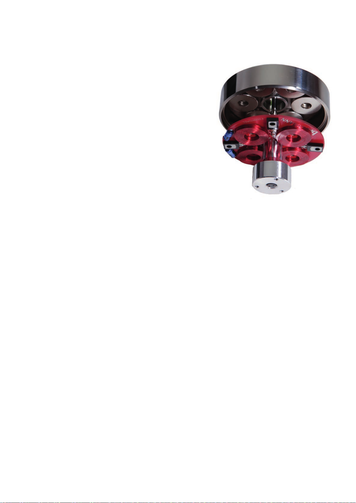
Compared to the Papst, Brinkmann’s new Sinus
circuitry—as opposed to the commonly used two-phase design used by Pabst and others--enab-
-
supply, which also enhances Brinkmann direct drive motors.
-
-
-
from the moment of turn-on.
8

Belt drive using Sinus 4 -Phase, 12-Pole motor
External solid-state power supply is Standard Equipment. RöNt II External, vacuum-
)
9

6. SET UP OF BALANCE TURNTABLE
The Balance turntable is available in both 1-arm and 2-arm versions. Please note: because there
not be
upgraded to the 2-arm version.
Tool Kit
Ground Cord
Spacer
Chassis
10

Extending or withdrawing the spikes and the amount of contact that the chassis has to the surface
for the spindle when
Motor
The
-
The cap screw prevents unin-
There are 2 holes at the rear of the
the “trim pots” used for speed ad-
11

Power Supply
Tonearm base
Before playing LPs: Please make sure to connect the ground cord (included) between the tonearm

7. SET UP OF SPYDER TURNTABLE
The Spyder
Tool Kit
Bearing Housing

Jigs with tonearm pods
-
aring via 2 screws. The most convenient tonearm posi-
The 2 blue screws supplied by Brinkmann are actually
commend using these screws ONLY to mount the jig(s)
-
Motor
II

to either speed switch. They give access to the trim pods for the speed adjustment. The screwdriver
creases the speed.
Power Supply
when the power supply is connected.
Tonearm base
plate.
The top plate holds the locking collar for the tonearm
Standard top plate).
mounted on the tonearm pod via 3 screws and are
Before playing LPs: Please make sure to connect the ground cord (included) between the tonearm

8. GENERAL INFORMATION FOR BRINKMANN DIRECT DRIVE TURNTABLES
-
16


9. SET UP OF OASIS TURNTABLE
The Oasis
Oasis. (The Bardo-
Oasis
Tool Kit
Spacer
Plinth / Motor
RöNt II
18

There are 2 holes located next to either speed switch. They give access to the trim pods for the
Before playing LPs: Please make sure to connect the ground cord (included) between the tonearm
bearing to keep it centred.
Power Supply
when the power supply is connected.
Tonearm base
The top plate holds the locking collar for the tonearm and clamps via 3 screws. By loosening the
screws, the top plate can be rotated 360° to adjust the correct pivot to spindle distance for the
tonearm and, when used with the Brinkmann Stylus Protractor, facilitates foolproof, highly accurate
and are exchangeable.
Brinkmann tonearm bases can be drilled for virtually all current tonearms.

10. SET UP OF BARDO TURNTABLE
The Bardo combines the direct drive technology of the Oasis with the classic Brinkmann “Plinthless”
chassis structure pioneered in the Balance. Bardo can mount tonearms from 9” to 12”.
Tool Kit
M3 allen key to clamp tonearm top plate and height adjustment of Bardo foot
Small Screwdriver for speed adjustment
Ground Cord
Spacer
Circular Felt Mat for Clamp
Chassis / Motor
Place the chassis on a levelled surface.
The chassis features 3 feet whose main purpose is for resonance control and discharge of unwanted
resonances. The foot next to the tonearm base can be accessed through a hole in the chassis, the
other 2 feet can be moved up and down by turning the feet.
RöNt II tubed power supply
connects to the 3-pole socket at the rear of the chassis to supply the motor. The cap screw prevents
unintended removal of the cord.
20
This manual suits for next models
3
Table of contents
Other Brinkmann Turntable manuals