BRINKS BC40107 User manual

Optional Optional Optional Optional Optional
CAUTION:
Please use four alkaline batteries for the best performance.
A. Please change programming code before operating this lockset.
The following instructions should be followed to protect and maintain
your lockset:
A. Do not use any chemical products containing alcohol, benzene,
hydrochloric acid or nitric acid, and avoid using sharp or abrasive
objects to clean this lockset.
B. Periodically clean with mild soap and a soft cloth only.
CARE and MAINTENANCE
Pre-installation — Tools Required / Hardware Included
To view these instructions
online or for a Spanish
version, scan this QR code.
Table of Contents
Parts List ..................................................................... 2
INSTALLATION INSTRUCTIONS .................................... 3
Step 1 Door Preparation ......................................................... 3
Step 2 Door Jamb Preparation ............................................. 3
Step 3 Select the Proper Latch Backset................................. 4
Step 4 Install the Latch ......................................................... 4
Step 5 Preparation for Installation.......................................... 5
Step 6A Setting the Exterior Spindle (Right Hand Door) ......... 6
Step 6B Setting the Interior Spindle (Right Hand Door)............ 6
Step 6C Setting the Exterior Spindle (Left Hand Door) ............ 7
Step 6D Setting the Interior Spindle (Left Hand Door) ............ 7
Step 7 Installing the Exterior Assembly ................................. 8
Step 8 Installing the Interior Assembly ................................. 8
Step 9 Locking & Unlocking ................................................... 10
Step 10 Programming ............................................................ 11
Step 11 Restoring to Factory Settings .................................... 12
Step 12 Troubleshooting ......................................................... 13
APPENDICES
Appendix A Removing Levers for Rekeying or Re-Handing ......... 15
Appendix B Removing & Replacing the Cylinder and Collar ......... 16
INSTALLATION INSTRUCTIONS FOR
KEYPAD ENTRY MODEL: BC40107
999-00823
PAGE 1

ELatch 1
F1
G
Mounting Plate
1
A Key
B Cylinder
C Exterior Assembly
D Power Cable
1
2
1
1
Part Description
Quantity
Interior Assembly
H
I Battery Cover
Decorative Cover 1
JLever
1
K
L
M
N
Strike Plate
Dust Box
2
1
Collar
Round Corner Faceplate
1
1
2
Part Description
Quantity
See Note 1
See Note 1 & Note 2
Note 1: Cylinder (B) and collar (N) are pre-installed in the exterior lever (J).
Note 2: Collar (N) is pre-installed on interior lever (J).
INTERIOR TURN SWITCH
1. It is auto-locked when the turn switch is vertical.
2. Lockset is set to passage mode when turn
switch is horizontal.
3. The turn switch must be in horizontal position to
enter programming mode. Exit Programming
mode by rotating the switch to vertical position.
INDICATORS
1. Red light: Represents an incorrect entry
or the unit is in programming mode.
2. Yellow light: Flashes when the batteries
are low in power.
3. Green light: Represents a correct entry.
CLEAR BUTTON
1. When there is an input error, use
©button to clear all input typos.
N
L
C
F
J
H
I
BB
EE
DD
T1
E
M
K
BATTERY COVER
1. Protects the batteries from
unexpected damage.
INTERIOR INDICATOR LIGHT
1. Flashes when the batteries are low in power.
MECHANICAL CYLINDER OVERRIDE
1. To unlock the lockset by a valid key.
A
G
B
N
D
J
BB — 1-1/4" (32mm) Mounting Plate Screws [Qty: 2]
DD — 5/16" (8mm) Battery Compartment Screws [Qty: 2]
EE — 3/4" (19mm) Latch & Strike Plate Screws [Qty: 4]
T1 — Catch tool [Qty: 1]
For questions, call:
1-866-LOCK-PRO
(1-866-562-5776)
PAGE 2

2Door Jamb Preparation
Prepare the door jamb – use the strike plate as a template to drill 1/8" screw holes and chisel out the mortise. The
strike plate must t ush with the surface of the door jamb.
NOTE: If your door is pre-drilled, check the hole sizes to make sure they are the proper size. If they are the proper
size, skip to Step 3.
1Door Preparation
Depth of latch hole
Outline
Faceplate (M)
Chisel 5/32” (4 mm) deep
NOTE: Drill from both
sides of the door to
prevent wood splitting.
Use the included template to mark the door and drill holes, and the latch (E) to chisel out the mortise.
Backset
Centerline
1"
25 mm
1"
(25 mm)
2-1/8"
(54 mm)
2-1/8"
(54 mm)
a.
c. d.
b.
Door jamb hole dimension:
a. 1/2" (13 mm)
b. 1-1/4" (32 mm)
c. 1" (25 mm)
Strike dimension:
d. 1/8" (3 mm)
e. 2-5/16" (58 mm)
f. 1/8" (3 mm) X 2
Strike Plate
(K)
Dust box (L)
Strike Plate (K)
c
b
a
d
eStrike
Screws
(EE) (2)
1/8"
3 mm
2X
PAGE 3

Be sure the bevelled face of the latch bolt
is towards the door jamb.
4Install the Latch
CAUTION:
Be sure the latch cam is upright before making any backset adjustment.
3Select the Proper Latch Backset
2-3/8" (60 mm)2-3/4" (70 mm)
2-3/8" - or - 2-3/4"
60 mm - or - 70 mm
a. c.
a. Backset is the distance from the door edge to the center of the 2-1/8" (54 mm) hole on the door face.
b. The latch (E) can be adjusted to t either a 2-3/8" (60 mm) or a 2-3/4" (70 mm) Backset by sliding the Cam
with the square hole towards or away from the latch. The 2-3/8" Backset is common for residential doors.
Sleeve Cam
Latch (E) Right
Wrong
Latch Screws (EE)
Bevelled face of the bolt
a. Insert the latch into the 1" hole in the door edge as
shown.
b. Insert two Latch Screws (EE) through the holes in the
faceplate and tighten rmly.
Latch (E)
PAGE 4

5Preparation for Installation
5A. Determine the Handing of the Door
A1. As you stand outside the room looking at the exterior
face of the door:
• If the hinges are on the left, it is a Left Hand door.
• If the hinges are on the right, it is a Right Hand door.
The lever can be installed on doors that swing into a room
or swing out of a room.
A2. This leverset is packaged with the exterior & interior spindles in the neutral position (non-handed) with the lever
catch facing down.
A3. Both spindles must be set to the correct handed position in Step 6 before installation.
5B. Insert Key in Exterior Lever Assembly
B1. The exterior lever (J) has the cylinder (B) and collar (N) pre-installed. Insert the key (A) while holding the lever and
cylinder tailpiece together to prevent accidental component removal.
Do not remove the label on the lever until after installation.
HingesHinges Exterior
Right Hand DoorLeft Hand Door
Spindle
Lever Catch Lever Catch
Hold lever and tailpiece
to insert key
CAUTION:
DO NOT PROCEED WITH INSTALLATION WITHOUT SETTING THE EXTERIOR & INTERIOR
SPINDLES FOR THE HAND OF YOUR DOOR!
Lever Catch
PAGE 5

6A
Setting the Exterior Spindle — (Right Hand Door) Note: If you have a left hand door skip to page 7.
6B
Setting the Interior Spindle — (Right Hand Door)
A1. Rotate the exterior spindle clockwise
90 degrees until it clicks into place.
The lever catch will
face away from the
hinges of the door.
A2. Align the exterior lever assembly with the spindle.
Rotate the key 90 degrees counter-clockwise.
Insert the lever onto the spindle
until it clicks into
place on the
lever catch.
A3. Rotate the key 90 degrees
clockwise back to its home
position and remove.
Remove the label.
After installation, the exterior lever will
point towards the hinges of the door.
Hinges
Right Hand
Door
Lever catch
away from
hinges
Interior
Assembly (G) Battery
Cover (I)
Exterior
Assembly (C)
90°
90°
B1. Rotate the interior spindle counter-clockwise
90 degrees until it clicks into place. The lever
catch will face away from the hinges of the door.
B2. Remove the battery cover (I) from the interior assembly
(G) by lifting it up and pulling out from its top and set it
aside.
Lever catch away
from hinges
PAGE 6

6C
Setting the Exterior Spindle — (Left Hand Door)
6D
Setting the Interior Spindle — (Left Hand Door)
90°
90°
C1. Rotate the exterior spindle counter-clockwise
90 degrees until it clicks into place.
The lever catch will
face away from the
hinges of the door.
C2. Align the exterior lever assembly with the spindle.
Rotate the key 90 degrees counter-clockwise. Insert
the lever onto the
spindle until it
clicks into place
on the lever
catch.
C3. Rotate the key 90 degrees
clockwise back to its home
position and remove.
Remove the label.
Lever catch away
from hinges
Exterior
Assembly (C)
D1. Rotate the interior spindle clockwise 90 degrees
until it clicks into place. The lever catch will face
away from the hinges of the door.
D2. Remove the battery cover (I) from the interior assembly
(G) by lifting it up and pulling out from its top and set it
aside.
Hinges Left Hand
Door
Interior
Assembly (G)
Battery
Cover (I)
Lever catch
away from
hinges
After installation, the exterior lever will
point towards the hinges of the door.
PAGE 7
6D
Setting the Interior Spindle — (Left Hand Door) (continued)
7Installing the Exterior Assembly
(Right Hand door installation shown below)
A. Place the exterior assembly (C) against the exterior
face of the door while inserting its square drive
spindle through the square hole in the latch cam.
Run the power cable (D)
under the latch.
B. Insert the power cable though the slot in the
mounting plate (F).
C. Orient the alignment
post of the mounting
bracket with the
corresponding post on
the exterior assembly
and press the mounting
bracket against the
interior door face.
D. Insert two mounting plate
screws (BB) through the holes
in the mounting plate and
engage the screw posts of the
exterior assembly. Tighten
rmly. Check to make sure
that the exterior assembly
does not look crooked with
respect to the door.
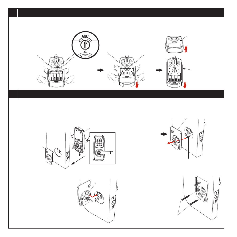
3. Remove the decorative cover (H) from the interior
assembly by pressing on the interior turn switch
with your thumbs and
separating the cover
from the body. Set
cover aside.
4. Separate the decorative cover and set it aside with
the battery cover.
Interior
Assembly (G)
Interior Turn
Switch
Press
Decorative
Cover (H)
Power Cable (D)
Mounting
Plate (F)
Alignment
Post
Mounting Plate (F)
Mounting Plate
Screws (BB) [2]
Exterior
Assembly (C)
PAGE 8

Proceed to the User Guide for programming the lockset.
Interior
Assembly (G)
8Installing the Interior Assembly
A. Insert power cable (D) rmly into the connector port
on the interior assembly (G). Secure the cable in the
cable guard. Align the square hole in the interior
assembly with the square drive spindle of the exterior
assembly and press the interior assembly against the
interior door face.
B. Insert two battery compartment screws (DD) and
tighten rmly.
C. Align and press the decorative cover (H) onto the
interior assembly. Make sure that the collar (N) is
placed correctly on the interior lever (J) and install
the interior lever assembly onto the interior spindle
until it clicks into place. The lever will point towards
the hinges.
D. Insert four new alkaline AA batteries in the battery
compartment. Install the battery cover (I) by hooking
the bottom into the corresponding slots in the interior
assembly. Rotate it up and let it drop down into place.
Decorative Cover (H)
Collar (N)
Interior
Lever (J)
Battery Compartment Screws (DD) [2]
Install batteries Install battery cover
Power Cable (D)
Connector Port
Cable Guard
PAGE 9

9How to Lock / Unlock / Program the Lockset
AUTO-LOCK / PASSAGE MODE
Auto-lock
Passage mode
HOW TO UNLOCK THE LOCKSET
To unlock
A
B
Use a mechanical key to lock or unlock.
When using the key, the lever functions as a Storeroom function lock in
which the exterior lever must remain locked when the key is removed.
Use a at tool to turn the slotted interior turn switch clockwise as shown from
vertical position to horizontal position to deactivate auto-locking mode. The device
then serves as a passage lever and is in programming mode.
After programming, turn the interior turn switch back to vertical to exit
programming mode and record programming changes.
Enter the correct user code or programming code.
Upon the green indicator light on and a short beep heard, turn the outside lever
to unlock.
When the green indicator light turns on and a short beep is heard, turn the
exterior lever to unlock.
Rotate interior turn switch
clockwise to horizontal
position as shown to
deactivate auto-locking
mode.
The keypad is temporarily disabled after 4 consecutive incorrect entries.
An alarm beep will sound for 10 seconds followed by a 60 second
lockout while the indicator light blinks red.
2
1
PAGE 10
Other manuals for BC40107
1
Table of contents
Other BRINKS Door Lock manuals


