manuals.online logo
Brands
  1. Home
  2. •
  3. Brands
  4. •
  5. Lockly
  6. •
  7. Door Lock
  8. •
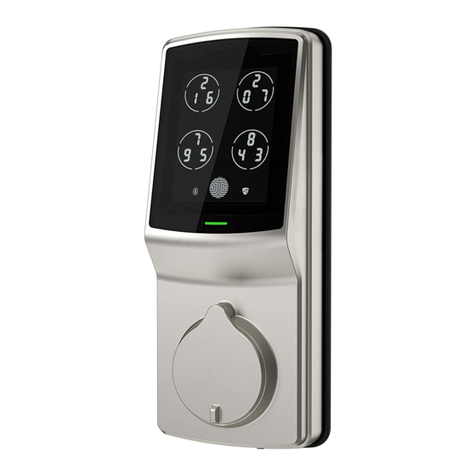
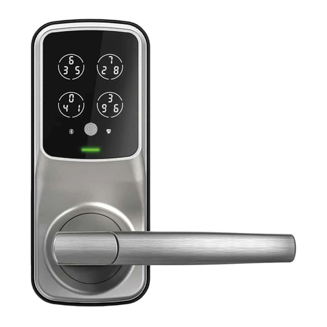
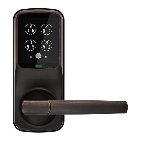
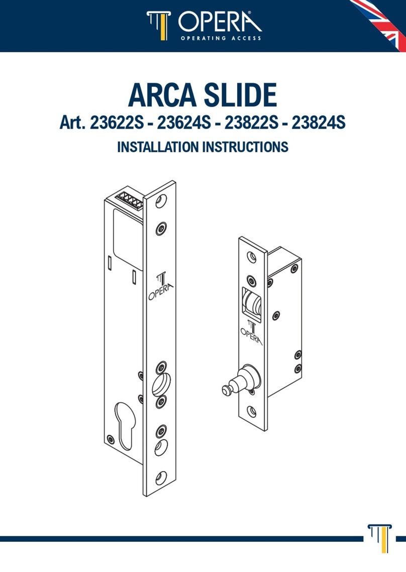
  9. Lockly Secure LUX User manual

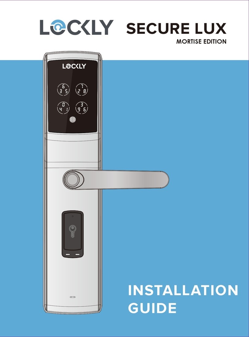
Lockly Secure LUX User manual

MORTISE EDITION
INSTALLATION MANUAL
LUX MORTISE LOCK
SECURE
INSTALLATION OVERVIEW
LocklyTM Secure can be fitted for both right swing doors and left swing doors.
Screw
Strike
Buckle Box
Exterior Panel
Lock Cylinder
Lock Cylinder Screw
Shaft
Lockset
Lockset Fixing
Screws
EVA
Escutcheon
Escutcheon Pad
Escutcheon Fixing Screw
Screw for Inner Panel
Screw Cap
Interior Panel Fixing Screw
Interior Panel
Flat Shaft
Battery Cover
PARTS LIST
Interior Panel Screw (1)
Screw for Inner Panel (2)
Positioning Sleeve (1)Lock Cylinder Screw (2)
Wrench(X1)
Cotter Pin (1)
50~60MM STANDARD DOOR THICKNESS
Screw for Lockset (4) Strike Screw (2) Screw Cap (2) Escutcheon Screw Pad (2)
Position Pad (2)
Shaft (1)
Cotter Pin hole is here
when door thickness is
larger than 70mm
Cotter Pin hole is here
when door thickness is
less than 70mm
Turnable Flat Strip (1)
Buckle Box (1)
Strike (1)
Lock Cylinder (1)
Stabilizing Screw (2) Screw for Exterior Panel (2)
KNOW YOUR DOOR
RIGHT IN-SWING DOOR
Make sure the latch throw is
correctly oriented as shown to fit
your right in-swing door
Make sure the pit hole is
correctly oriented as shown.
There are 4 common door-opening directions, the lockset configuration as shown
on each diagram below corresponds to the respective door-opening direction.
RIGHT OUT-SWING DOOR
Make sure the latch throw is
correctly oriented as shown to fit
your right out-swing door
Make sure the pit hole is
correctly oriented as shown.
LEFT IN-SWING DOOR
Make sure the latch throw is
correctly oriented as shown to fit
your left in-swing door
Make sure the pit hole is
correctly oriented as shown.
KNOW YOUR DOOR
- This lock is suitable for wooden doors and steel doors with a thickness of 40~120mm.
- First you must identify the opening direction of your door before installation.
- Adjust the direction of the corresponding lockset to fit your door with the exterior and
interior panels.
Follow the steps on the next pages to adjust your latch throw, cylinder
and door handle.
IMPORTANT NOTICE
LEFT OUT-SWING DOOR
Make sure the latch throw is
correctly oriented as shown to fit
your left out-swing door
Make sure the pit hole is
correctly oriented as shown.
HOW TO ADJUST THE LATCH THROW
Here is how to change the latch throw direction. The factory setting of the throw is for right
in-swing door. You do not need to change direction if you have a right in-swing door.
1. You need a Phillips screwdriver.
4. Fix the strike plate with mounting
screws.
2. Unscrew the strike plate then turn the
latch throw by 180 degree.
3. Turn the latch throw by 180
degree.
HOW TO ADJUST THE CYLINDER
Here is how to change the cylinder direction. The factory setting of the cylinder is for
right in-swing door. You do not need to change direction if you have a right in-swing
door.
the spin
+ is adjusted
to the outside
of the door
The spin can only be slotted in when
the pit hole is at the downside.
3. You must have the cross slot
of the spin facing this side.
4. Fix the strike plate with mounting
screws.
1. You need a Phillips screwdriver.
the spin
current position
of the spin
The spin can only be taken out
when the pit hole is facing down
2. Unscrew the strike plate and take out the
spin as shown then turn it to the revise side
of the lockset.
HOW TO ADJUST THE DOOR HANDLE
*The diagram below shows how to shift the door handle from right to left direction. The
factory setting of the handle is for right handed door. You do not need to change
direction if you have a right handed door.
Allen Wrench
3. Lock the two screws
with an Allen key
1. Remove the two
screws with an
Allen key
2. Pull the hook backwards with
your finger to the right position.
Then rotate the handle 180°. It is
now done.
STEP 1: PREPARING YOUR DOOR
Make sure your door is prepared for installation. You may need to drill a new hole.
Please use the supplied template for drilling holes required before installation. You will
need some tools or a hole-saw.
Centerline above
1M from ground.
Hole for handle
Hole template
STEP 2: INSTALLING THE LOCKSET
Install the mortise lockset into
door pocket and tighten it with the 4 screws supplied.
Route the cable inside the door pocket and place it aside.
Fixing Screws (X4)
Lockset
Route the cable inside the door
Make sure the pit hole of this
spin is pointed downward
and facing the door outside
during installation.
Make sure the lock cylinder is aligned with the door holes then fix it with 2 screws to
the exterior panel. Consequently fix the two spindles and the spindle pads as shown
with pliers.
Lock Cylinder
Fixing Screws for
Lock Cylinder(X2)
Spindle(X2)
Spindle Pad(X2)
Remove this plastic
cover before installing
the lock cylinder.
23.5
1 2 3 4
STEP 3. INSTALLING THE LOCK
CYLINDER AND THE SPINDLE
Note: If the door thickness is less than
70mm cut screw for outer panel to
23.5mm, that is from the 4th scale
cut-off to the end.
STEP 4. INSTALLING THE EXTERIOR PANEL
4.1 Insert the square shaft through the exterior panel. Cut the shaft according to the
door thickness. Then install the exterior panel, shaft, EVA and the escutcheon in place.
4.2 Route both the lockset and exterior panel cables through the corresponding holes
then insert the positioning sleeve into the inner side of the square shaft. Make sure they
are all aligned and correctly oriented.
4.3 Check both inner and outer handles if they are in smooth operation. Then check if
the locking and unlocking operations are smooth. If not, adjust the mounting screws
until the the operation is running smooth. See illustration as shown below:
Note: This shaft needs to be inserted through the outer part of the door
Position Sleeve
(Should be removed
after the shaft is
positioned)
Outer Panel Fixing
Screw Gasket
Outer Panel
Fixing Screw
EVA
Escutcheon
Shaft
Shaft Installation
Inside Door: The shaft
must be inserted in place
after installation. The shaft
must pass through
completely the lock body,
as shown below.
Outside Door: After the
shaft is installed, pull the
shaft outward by hand in
the direction of the arrow,
and ensure the shaft
cannot be pulled out.
STEP 5 . INSTALLING THE INTERIOR PANEL
Remove and discard the positioning sleeve then insert both lock cables to the correspond-
ing socket of the interior panel. Insert the cotter pin to the flat shaft. See notes as illustrated
in the diagram. Then insert the flat shaft to the corresponding holes and tighten with screws
provided.
Flat Shaft
Fixing Screw
Fixing Screws
Battery Cover
Cotter Pin
Turnable Flat Strip
When deadbolt is
scaled back, the
thumb turn is on
vertical position.
When the door thickness is
greater than 70mm, insert
the cotter pin through this
hole. When the door thickness is
less than 70mm, insert the
cotter pin through this hole.
STEP 6. FINAL CHECK
STEP 7. INSTALLING BATTERIES
After installation is completed, lift both the
interior and exterior handles up and down
making sure they are running smoothly.
Then check if the deadbolt and strike
plate is thrown smoothly with the physical
keys.
Check the functions of the lock
per user manual after installing the
batteries. Make sure the
batteries
are correctly positioned. Then close
the battery cover.
Screw Caps
Install the buckle box as shown
below. Open the door frame,
install buckle box, then the
strike plate and fix it with
screws.
STEP 8. PREPARING THE DOOR
FRAME AND MOUNTING PLATE
Fixing Screws
Strike Buckle Box
When installing to a
wooden door, cut the
buckle box as shown.
No need to cut when
you have a metal door.
SECURE
IGPGD82920190423
For an online version of this installation guide and videos, visit:
http://lockly.com/help

Other manuals for Secure LUX

1

Other Lockly Door Lock manuals

Lockly FLEX TOUCH User manual

Lockly

Lockly FLEX TOUCH User manual

Lockly Secure LUX User manual

Lockly

Lockly Secure LUX User manual

Lockly LATCH EDITION 6S User manual

Lockly

Lockly LATCH EDITION 6S User manual

Lockly DEADBOLT EDITION PGD1128FPW User manual

Lockly

Lockly DEADBOLT EDITION PGD1128FPW User manual

Lockly LUX COMPACT PGD688F-MB User manual

Lockly

Lockly LUX COMPACT PGD688F-MB User manual

Lockly PRO User manual

Lockly

Lockly PRO User manual

Lockly PGD728F User manual

Lockly

Lockly PGD728F User manual

Lockly DEADBOLT EDITION 7S User manual

Lockly

Lockly DEADBOLT EDITION 7S User manual

Lockly SECURE LUX MORTISE EDITION User manual
Lockly

Lockly SECURE LUX MORTISE EDITION User manual

Lockly FLEX TOUCH PRO User manual

Lockly

Lockly FLEX TOUCH PRO User manual

Lockly ACCESS TOUCH PRO User manual

Lockly

Lockly ACCESS TOUCH PRO User manual

Lockly DEADBOLT EDITION 7S User manual

Lockly

Lockly DEADBOLT EDITION 7S User manual

Lockly ACCESS TOUCH PRO User manual

Lockly

Lockly ACCESS TOUCH PRO User manual

Lockly LATCH EDITION SECURE PGD628 User manual

Lockly

Lockly LATCH EDITION SECURE PGD628 User manual

Lockly SECURE PRO User manual

Lockly

Lockly SECURE PRO User manual

Lockly LUX COMPACT PGD688FSN User manual

Lockly

Lockly LUX COMPACT PGD688FSN User manual

Lockly DEADBOLT EDITION 7S User manual

Lockly

Lockly DEADBOLT EDITION 7S User manual

Lockly LATCH EDITION SECURE PGD628 User manual

Lockly

Lockly LATCH EDITION SECURE PGD628 User manual

Lockly LATCH EDITION SECURE PGD628 User manual

Lockly

Lockly LATCH EDITION SECURE PGD628 User manual

Lockly VISION ELITE Instruction Manual

Lockly

Lockly VISION ELITE Instruction Manual

Lockly MORTISE EDITION SECURE LUX PGD829AFUS User manual

Lockly

Lockly MORTISE EDITION SECURE LUX PGD829AFUS User manual

Lockly DEADBOLT EDITION PGD1128 User manual

Lockly

Lockly DEADBOLT EDITION PGD1128 User manual

Lockly SECURE PLUS User manual

Lockly

Lockly SECURE PLUS User manual

Lockly LATCH EDITION SECURE PLUS User manual
Lockly

Lockly LATCH EDITION SECURE PLUS User manual

Popular Door Lock manuals by other brands

ABH LR6000 Series installation instructions

ABH

ABH LR6000 Series installation instructions

LOCKLY GUARD VISION DUO user manual

LOCKLY GUARD

LOCKLY GUARD VISION DUO user manual

Kwikset Smartcode 888 Installation and user guide

Kwikset

Kwikset Smartcode 888 Installation and user guide

Häfele DL6500 user manual

Häfele

Häfele DL6500 user manual

Netatmo NDL01 manual

Netatmo

Netatmo NDL01 manual

SDC E72 EntryCheck Program guide

SDC

SDC E72 EntryCheck Program guide

MAASLAND SE-APB1-1T manual

MAASLAND

MAASLAND SE-APB1-1T manual

Von Duprin 375-L installation instructions

Von Duprin

Von Duprin 375-L installation instructions

Griffwerk PURISTO S quick start guide

Griffwerk

Griffwerk PURISTO S quick start guide

HES 1500 Series installation instructions

HES

HES 1500 Series installation instructions

Zebratti LCS Series Installation instruction

Zebratti

Zebratti LCS Series Installation instruction

SDC 1291 ADMR Spacesaver installation instructions

SDC

SDC 1291 ADMR Spacesaver installation instructions

Schlage B660 installation instructions

Schlage

Schlage B660 installation instructions

Assa Abloy OneSystem N1940 manual

Assa Abloy

Assa Abloy OneSystem N1940 manual

Salto AELEMENT LA1T17 Series Change instructions

Salto

Salto AELEMENT LA1T17 Series Change instructions

Stanley QET100 Series installation instructions

Stanley

Stanley QET100 Series installation instructions

Salto Neo M1 Series installation guide

Salto

Salto Neo M1 Series installation guide

Burg TwinPad operating manual

Burg

Burg TwinPad operating manual

manuals.online logo
manuals.online logoBrands
  • About & Mission
  • Contact us
  • Privacy Policy
  • Terms and Conditions

Copyright 2025 Manuals.Online. All Rights Reserved.