Brinly SATY-40 BH User manual
L-1643BH-HPage 1
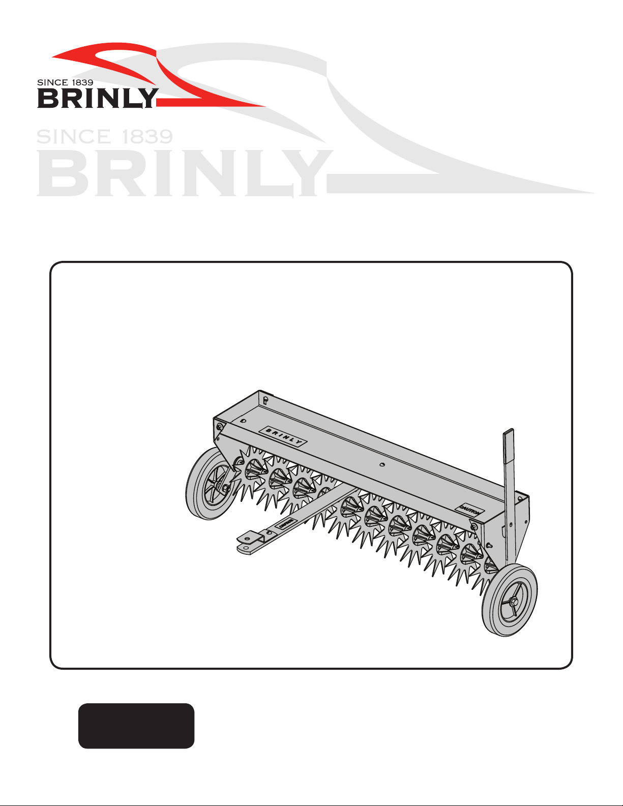
40" LAWN AERATOR
MODEL:
SAT-40 BH
• Assembly
• Installation
• Operation
• Repair Parts
OWNER'S MANUAL
Important: This manual contains information for the safety of persons
and property. Read it carefully before assembly and operation
of the equipment!
Visit us on the web!
www.brinly.com
For the latest product updates & setup tips:

L-1643BH-HPage 2
================================================================================================
INTRUDUCTION
CUSTOMER RESPONSIBILITIES
Please read and retain this manual. The instructions enables
you to assemble and maintain your lawn aerator properly. And
please, always observe the “Safety” instructions.
TABLE OF CONTENTS
SAFETY ............................................... 2-3
PARTS REFERENCE ............................ 4
ASSEMBLY .......................................... 5-9
OPERATION ........................................ 10
SERVICE ............................................... 11
WARRANTY ........................................ 12
RECORD PURCHASE INFORMATION
Record your purchase information in the spaces provided below:
DATE OF PURCHASE: __________________________________
COMPANY NAME: _____________________________________
COMPANY PHONE: ____________________________________
SERIAL NUMBER: _____________________________________
==============================================
SAFETY LABELS AND NOTATION
This symbol will help point out important
safety precautions throughout this manual. It means -
ATTENTION! BECOME ALERT! Your safety is involved.
CONGRATULATIONS on the purchase of your new Brinly-Hardy Lawn Aerator! Your lawn aerator is designed, engineered and
manufactured to give you the best possible dependability and performance.
Should you experience any problem you cannot easily remedy, please do not hesitate to contact our knowledgeable customer
service department toll-free at 1-877-728-8224. Contamos con técnicos competentes y bien capacitados para ayudarlo con el
ensamblaje y el uso de su producto.
The safety labels shown in this section are
placed in important areas on your product
to draw attention to potential safety
hazards.
On your product safety labels, the words
DANGER, WARNING and CAUTION
are used with the safety-alert symbol.
DANGER identies the most serious
hazards.
The operator’s manual also explains
any potential safety hazards whenever
necessary in special safety messages that
are identiÿed with the word, CAUTION,
and the safety-alert symbol.
GENERAL NOTES (OPERATION)
Caution should be taken when towing and/or using any attachment.
This attachment combined with the weight distribution, turning radius,
and speed of towing vehicle can result in severe injury or death to
operator, damage to towing vehicle, and/or attachment if not used
properly. Follow all towing safety precautions noted in the towing
vehicle owner’s manual, including the following precautions:
• Ensure the combined weight of the towing vehicle (tow vehicle
weight + operator weight) is greater than the maximum towed
weight of attachment (empty attachment weight + weight of load).

L-1643BH-HPage 3
================================================================================================
SAFETY
• Do not exceed maximum towing capacity of towing vehicle.
• Do not exceed the maximum drawbar pull rating of the towing
vehicle. Drawbar pull is the horizontal force required to pull the
attachment (including weight of load).
• Only tow this product in the vehicle’s tow mode/ speed setting or
less than 5 mph. Do not exceed 5 mph.
• Towing speed should always be slow enough to maintain control.
Travel slowly and use caution when traveling over rough terrain.
Avoid holes, rocks and roots.
• Slow down before you turn and do not turn sharply.
• Use wide turning angles to ensure the attachment follows the path
of the towing vehicle.
• Do not use attachment on steep slopes. A heavy load could cause
loss of control or overturn attachment and towing vehicle. Additional
weights may need to be added to your vehicle; check with towing
vehicle manufacturer for recommendations.
• Reduce towed weight when operating on slopes.
• Keep all movement on slopes slow and gradual. Do not make
sudden changes in speed, directions, or turning.
• If you start and stop suddenly on hills, you may lose steering control
or the towing vehicle may tip. Do not start or stop suddenly when
going uphill or downhill. Avoid uphill starts.
• Slow down and use extra care on hillsides. Turf conditions can
affect vehicle stability. Use extreme caution while operating near
drop-offs.
• Do not drive close to creeks, ditches and public highways.
• Watch out for trafc when crossing near roadways.
• Use care when loading or unloading the vehicle into a trailer or truck.
• The attachment can obstruct the view to the rear. Use extra care
when operating in reverse.
• When reversing, carefully back-up straight to avoid jackkning. Do
not allow towing vehicle wheels to contact attachment draw bar.
Damage could result.
• Stop on level ground, disengage drives, set the parking brake, and
shut off engine before leaving the operator’s position for any reason
including emptying the attachment.
• Use this attachment for intended purpose only.
• This attachment is intended for use in lawn care & home applications.
Do not tow behind a vehicle on a highway or in any high speed
applications. Do not tow at speeds higher than the maximum
recommend towing speed.
• Do not tow this product behind a motor vehicle such as a car or
truck.
• Always wear substantial footwear. Do not wear loose tting clothing
that can get caught in moving parts.
• Keep your eyes and mind on your towing vehicle, attachment and
area being covered. Do not let other interests distract you.
• Stay alert for holes and other hidden hazards in the terrain
• Keep the towing vehicle and attachment in good operating condition
and keep safety devices in place.
• The towing vehicle and attachment should be stopped and inspected
for damage after striking a foreign object. Any damage should be
repaired before restarting and operating the equipment.
• Keep all parts in good condition and properly installed. Fix damaged
parts immediately. Replace worn or broken parts. Replace all worn
or damaged safety and instruction decals. Keep all nuts, bolts and
screws tight.
• Do not modify the attachment or safety devices. Unauthorized
modications to the towing vehicle or attachment may impair its
function, safety and void the warranty.
TOWING VEHICLE AND TOWING SAFELY
• Know your towing vehicle controls and how to stop safely. READ
YOUR TOWING VEHICLE OWNER’S MANUAL before operating.
• Check the towing vehicle brake action before you operate. Adjust or
service brakes as necessary.
• Stopping distance increases with speed and weight of towed load.
Travel slowly and allow extra time and distance to stop.
• Use only approved hitches. Tow this attachment only with a towing
vehicle that has a hitch designed for towing. Do not connect this
attachment except at the approved hitch point.
• Follow the tow vehicle manufacture’s recommendations for weight
limits for towed equipment & towing on slopes. Use counterweights
or wheel weights as described in the towing vehicle operator’s
manual.
• Do not shift to neutral and coast downhill.
• Do not allow children to operate the towing vehicle. Do not allow
adults to operate the towing vehicle without proper instruction or
without having read the owner’s manual.
PROTECT THOSE AROUND YOU
• Before you operate any feature of this attachment or towing vehicle,
observe your surroundings and look for bystanders.
• Keep children, bystanders and pets at a safe distance away while
operating this or any attachment.
• Use care when reversing. Before you back up, look carefully behind
for bystanders.
KEEP RIDERS OFF TOWED
ATTACHMENT AND TOWING VEHICLE
• Do not carry passengers.
• Do not let anyone, especially children, ride in/on this attachment, the
towing vehicle or hitch bracket. Riders are subject to injury such as
being struck by foreign object and/or being thrown off during sudden
starts, stops and turns. Riders may also obstruct the operator’s view
resulting in this attachment being operated in an unsafe manner.
L-1643BH-HPage 4
================================================================================================
PARTS REFERENCE
13
29
16
15
13
5
2
3
11
29
10
8
25
26
22
28
17
6
16
17
12
1
18 14
19
4
15
16
15
27
27
721
23
23
20
9
24
16
16
15
15
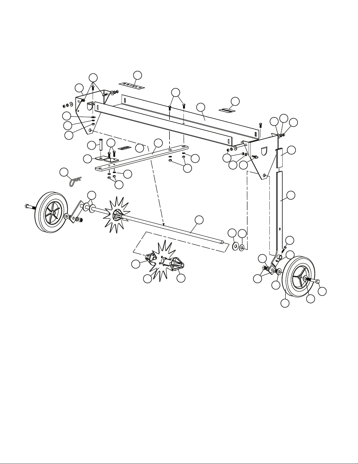
EXPLODED VIEW TOOLS REQUIRED FOR ASSEMBLY:
• 1 - Pair of work gloves
• 1 - Pair of pliers
• 1 - Screwdriver (at blade)
• 2 - 7/16” Wrenches
• 1 - 1/2” Wrench
• 2 - 3/4” Wrenches
PARTS LIST:
REF PART NO. DESCRIPTION QTY. REF PART NO. DESCRIPTION QTY.
1. R-821-10 Drawbar Clevis .....................1
2. B-5925 Logo Decal ........................1
3. B-5453-10 Tray ..............................1
4. B-3593-10 Drawbar ..........................1
5. B-4892-10 End Panel .........................2
6. B-5832-10 Axle Assembly .....................1
7. B-5423 Tine .............................11
8. B-4888-10 Handle Assembly ...................1
9. R-891 Wheel ............................2
10. B-4867 Handle Grip .......................1
11. R-1946 Caution Decal .....................1
12. D-146P Hairpin Cotter ......................1
13. 20M1012P Round Head Screw, 5/16”x3/4” ........8
14. 20M1016P Round Head Screw, 5/16”x1” .........2
15. 30M1000P Hex Nut, 5/16” ....................11
16. 40M1000P Lock Washer, 5/16” ................11
17. B-5456 Flat Washer, 5/8” (thick) ..............5
18. B-3861 Drawbar Pin .......................1
19. B-3922 Caution Decal .....................1
20. 1M1648P Hex Bolt, 1/2”x3” ...................2
21. 30M1600P Hex Nut, 1/2” ......................4
22. 40M1600P Lock Washer, 1/2” ..................2
23. 45M1717P Flat Washer, 1/2” ...................4
24. B-3307-S Transport Lock Pin ..................1
25. 2M0820P Hex Bolt, 1/4”x1-1/4” ................1
26. B-1673P Hex Lock Nut, 1/4” ..................1
27. B-5425 Spacer/Bearing, Tube ..............22
28. B-4768 Flat Washer, 5/8” (thin) ..............2
29. 45M1111P Flat Washer, 5/16” ..................6

L-1643BH-HPage 5
================================================================================================
3
4
41"
16
15
1
14
16
15
5
24
13
16
15
Step 1.
13
29 16 15
5
3
29
5/16" Flat Washer
Qty. 6
13
5/16" x 3/4" Rd Hd Screw
Qty. 6
16
5/16" Lock Washer
Qty. 6
15
5/16" Hex Nut
Qty. 6
ASSEMBLY
1a. Attach the two End Panels (5)
to the Tray (3) using the following
as illustrated:
x6 Round Hd Screws (13)
5/16” x 3/4”
x6 Flat Washers (29)
5/16”
x6 Lock Washers (16)
5/16”
x6 Hex Nuts (15)
5/16”
ATTACH END PANELS TO TRAY
Step 2.
15
5/16" Hex Nut
Qty. 5
16
5/16" Lock Washer
Qty. 5
14
5/16" x 1" Round Hd
Screw | Qty. 2
13
5/16" x 3/4" Round Hd
Screw | Qty. 2
24
Transport Lock Pin
Qty. 1
2a. Install drawbar (4) to the
tray (3) using the following
as illustrated:
x2 Round Hd Screws (13)
5/16” x 3/4”
x2 Lock Washers (16)
5/16”
x2 Hex Nuts, 5/16" (15)
2b. Attach Clevis (1) to Drawbar using the
following as illustrated:
x2 5/16” x 1” Rd Hd. Screws (14),
x2 Lock Washers, 5/16” (16)
x2 Hex Nuts, 5/16" (15)
2c. Attach Transport Lock Pin (24) to End Panel
(5) using one 5/16” Lock Washer (16) and 5/16”
Hex Nut (15), as shown.
NOTE: The inside distance between the
two end panels should be 41 inches
to ensure proper installation.
INSTALL DRAWBAR
L-1643BH-HPage 6
================================================================================================
Step 3. 6
17
27
5
17
7
28
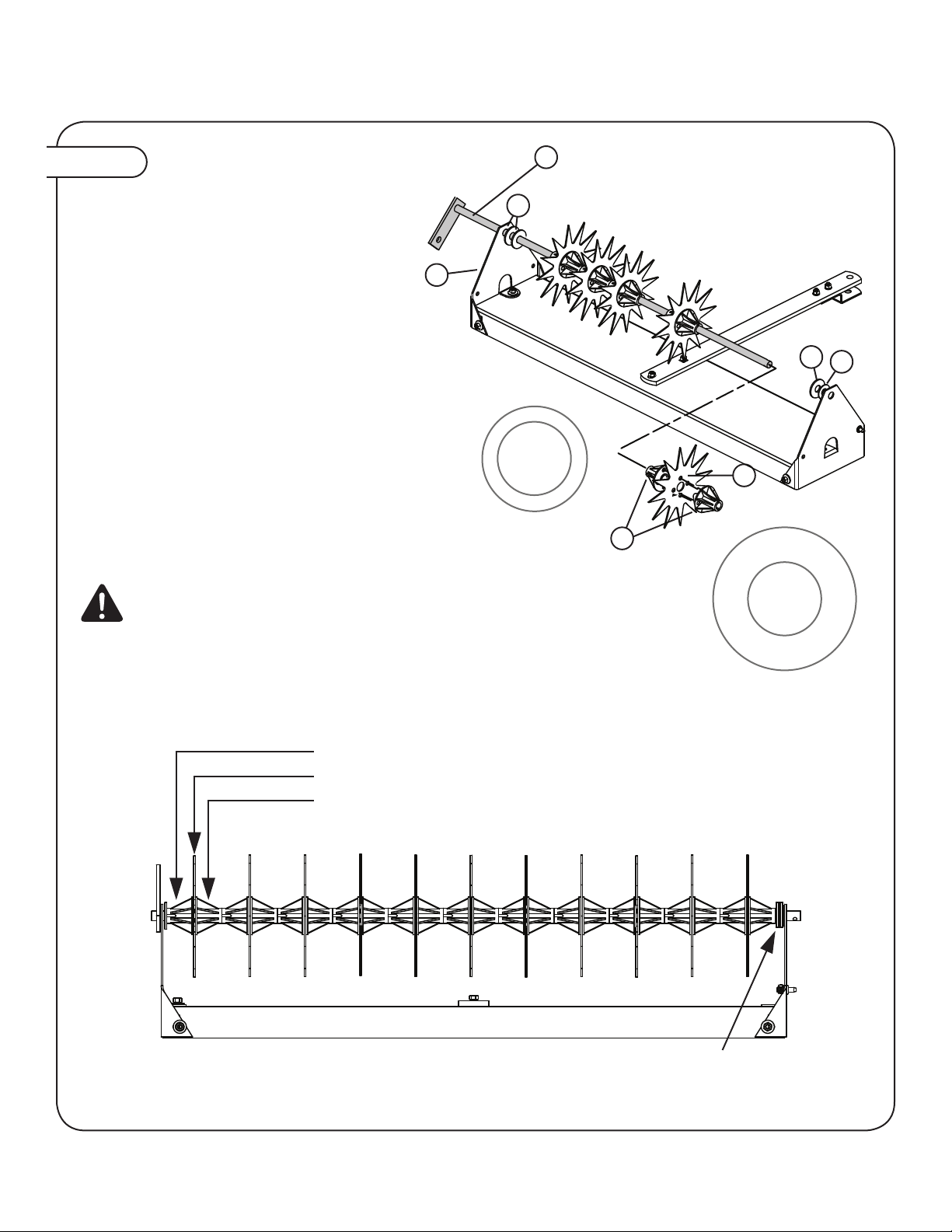
ASSEMBLY
3a. Place a 5/8” Flat Washer, Thick (17) onto
the Axle Assembly (6), then slide it through
the hole in End Panel (5 right Side) and add
another Flat Washer Thick (17) if needed.
3b. Position the eleven Tines (7) and twenty-two
Spacer/Bearing Tubes (27) onto the Axle
Assembly (6) as follows:
• Bearing, small end rst
• Aerator Tine
• Bearing, large end rst
Note: Round projections on Spacer /
Bearing anges must t into small holes in
aerator tines and into two holes of opposite
Spacer/Bearing
3c. Position one or two Washers (17 or 28) as
needed to eliminate any side-to-side movement
and push Axle Assembly (6) through hole in
the left End Panel (5) as far as possible. See
layout below.
ASSEMBLE TINES TO AXLE
28
5/8" Washer
(thin)
Qty. 2
17
5/8" Washer (thick)
Qty. 4
Tine and Spacer/Bearing Tube Layout:
• Spacer/Bearing Tube (small end rst)
• Aerator Tine
• Spacer/Bearing Tube (large ange rst)
Note: Tines must not move from side to side inside opening of end panels. If looseness exists, use additional 5/8"
Thick or Thin Washers (17 or 28) inside End Panel to eliminate any side movement.
WARNING: Gloves are required when handling
aerator tines. Tines have extremely sharp points.
Use caution when handling.

L-1643BH-HPage 7
================================================================================================
Step 4.
25
Hex Bolt, 1/4 X 1-1/4"
Qty. 1
26
Hex Lock Nut, 1/4"
Qty. 1
WHEEL BAR MOUNT
10
8
25
626
ASSEMBLY
4a. Attach the Handle Assembly (8) to end the of the Axle
Assembly (6) by inserting one 1/4” x 1-1/4” Hex Bolt (25)
though the hole in the end of the Axle Assembly) and
secure with 1/4” Hex Nut (26), as shown.
Note: The wheel bar mount on the Axle Assembly
must be positioned downward, as shown, in order to
properly attached the wheels.
4b. Slide the Handle Grip (10) on to the
Handle Assembly (8).
ATTACH HANDLE ASSEMBLY

L-1643BH-HPage 8
================================================================================================
ASSEMBLY
Step 5.
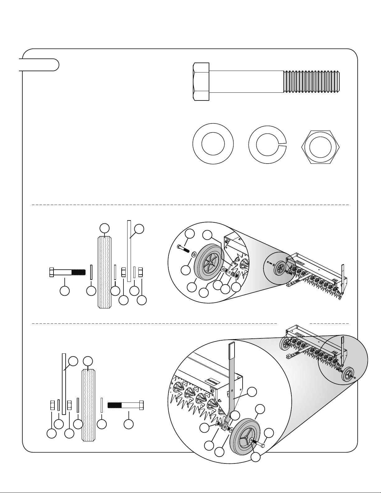
4a. Attach one Wheel (9) to the Handle Assembly (8)
and the other wheel to the wheel bar mount on the
Axle (6). Secure to each side using hardware in the
following order:
• 1/2” x 3” Hex Bolt (20)
• 1/2” Flat Washer (23)
• Wheel (9)
• 1/2” Flat Washer (23)
• 1/2” Hex Nut (21)
• 1/2” Lock Washer (22)
• 1/2” Hex Nut (21)
Note: Attaching wheel without all
of the proper hardware will cause the
wheel to wobble. Insure all hard-ware
is used, see insets below.
20
Hex Bolt, 1/2" x 3"
Qty. 2
22
Lock Washer, 1/2"
Qty. 3
23
Flat Washer, 1/2"
Qty. 4
21
Hex Nut, 1/2"
Qty. 4
9
8
232322
2121
20
LEFT WHEEL
RIGHT WHEEL
23
96
23 22
21 21
20
INSTALL WHEELS
20
921
23
22 21
23
6
8
9
23
22
21
21
20
23
L-1643BH-HPage 9
================================================================================================
Step 6.
18
12
8
24
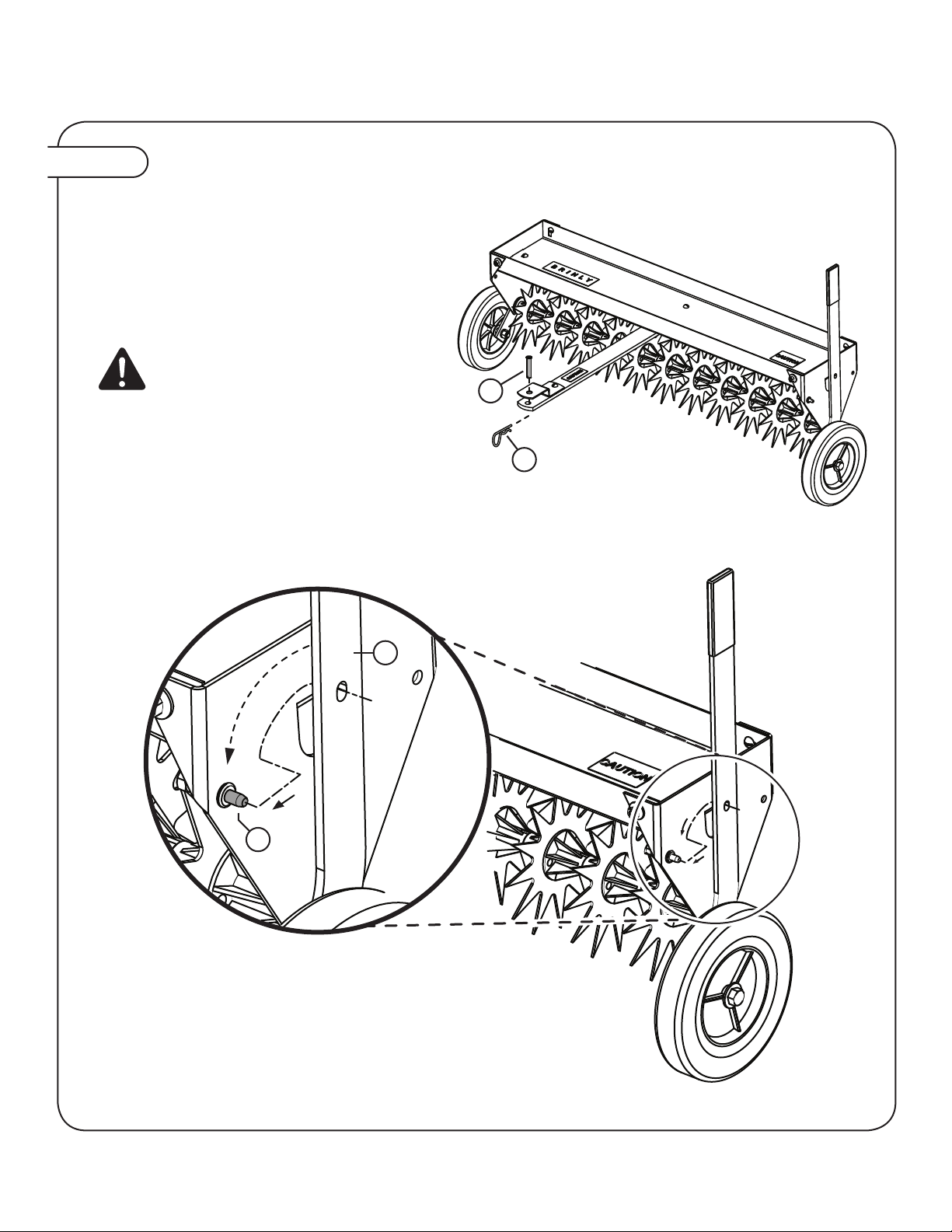
ASSEMBLY
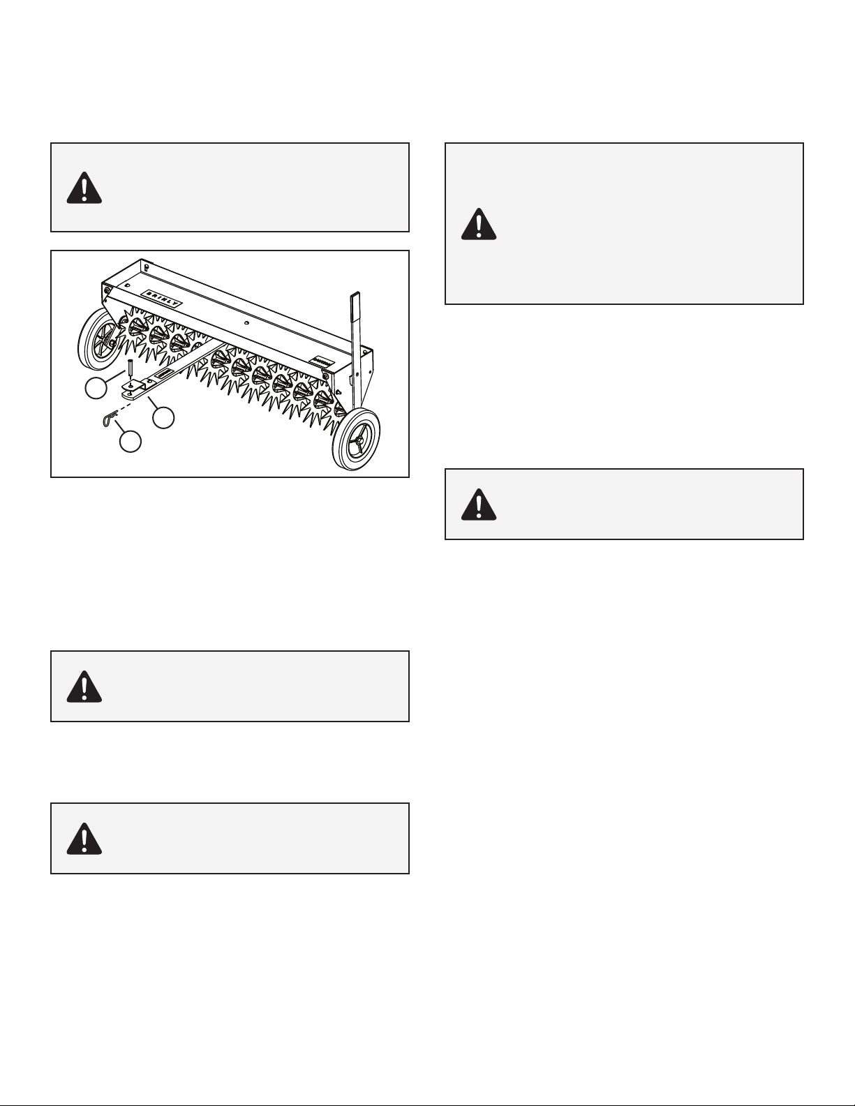
6a. Attach Aerator to your towing vehicle using Drawbar
Pin (18) and Hairpin Cotter (12) supplied.
6b. To place in Transport Position:
• Pull FORWARD on Handle Assembly (8).
• Pull out slightly and position over Transport
Lock Pin (24). Aerator rests on wheels.
6c. To place in Operating Position:
Pull OUT on Handle Assembly (releasing from
Transport Position) and push Handle BACK.
Aerator should rest on Tines.
MOUNTING & TRANSPORTING
CAUTION: Avoid damage to tines. Engage
the transport wheels when crossing concrete
or asphalt driveways and walkways.
L-1643BH-HPage 10
================================================================================================
OPERATION
INSTALLING YOUR AERATOR
1. Park machine safely. (See towing vehicle manual).
2. Align aerator clevis (A) with towing machine drawbar.
3. Install drawbar pin (B) through clevis and machine drawbar.
Secure drawbar pin with Hairpin Cotter (C).
=============================================
REMOVING AERATOR
1. Secure towing vehicle parking brake. (See towing vehicle
manual).
2. Place Aerator in the Transport Position.
3. Unload Aerator tray.
4. Remove cotter pin and drawbar pin.
5. Push aerator away from towing vehicle.
6. Install drawbar pin and cotter pin to towbar for storage.
CAUTION: AVOID INJURY!
Make sure feet and hands are clear of Tine Tips.
Avoid injury! Do not operate lift handle unless
attachment is installed to towing vehicle
CAUTION:AVOID INJURY!
Keep body parts away from under drawbar. Do not
attempt to disconnect aerator from towing vehicle
with weight on the tray.
CAUTION:AVOID INJURY!
Keep body parts away from under drawbar. Do not
attempt to disconnect aerator from towing vehicle
with weight on the tray.
OPERATING
USING THE WEIGHT TRAY
The following maximum loaded weight capacity is the weight of the
aerator plus the weight loaded in the tray:
MODEL WEIGHT CAPACITY
SAT 40BH 42 lbs. (Empty)
150 lbs. (Max Load)
192 lbs. Max Towed Weight
Towing capacity will vary with weight of towing vehicle and operator.
Add the weight of your machine to operator weight to nd the maximum
capacity for towing.
DEPTH/PENETRATION
Weight should be added to tray after installing to the towing machine.
Weight should be secured by rope, straps, or other suitable means to
contain the weight in the tray.
Weight tray maximum capacity = 150 pounds.
Moderate soil moisture is important for proper penetration. Extremely
dry conditions will not permit penetration and may damage the tines.
Extremely wet conditions will cause full pene-tration to the tine
spacers. This condition will cut slots in the turf.
SPEED
The best operating speed is 3 mph or less.
FREQUENCY
Aeration is not accomplished in a single pass. It will normally take
several passes over the lawn. Alternating the direction by 90° will
improve the aeration effect.
The aerator may be used in an independent operation or may be
used when mowing your lawn.
CAUTION:AVOID INJURY!
Avoid damage to tines. Engage the transport
wheels when crossing concrete or asphalt
driveways and walkways.
Excessive towed load can cause loss of control on
slopes. Stopping distance increases with speed
and weight of towed load.
Total towed weight must not exceed combined
weight of towing vehicle, ballast and operator.
CAUTION:AVOID INJURY!
Keep body parts away from under drawbar. Do not
attempt to disconnect aerator from towing vehicle
with weight on the tray.
B
C
A

L-1643BH-HPage 11
================================================================================================
SERVICE
MAINTENANCE
After the rst 30 minutes of use check all fasteners for tightness.
Tines are manufactured with galvanized steel to resist wear
of abrasive soil. Striking objects can cause tines to curl or
break. Contact our Customer Service Department to purchase
replacement Tines (Part # B-5423).
Aerator is essentially maintenance free. However as with any steel
product, it can rust. Apply a light coat of oil on tines after use to
prevent rust. For rust appearing on painted surfaces, sand lightly
and coat with enamel.
Periodically remove debris that builds up between tines.
Apply lubricating oil at each tine and bearing before use.
=============================================
SPECIFICATIONS
Maximum Towing Speed .................... 5 mph.
Maximum Load ........................... 150 lbs.
Empty Weight ............................. 42 lbs.
Maximum Towed Weight ................... 192 lbs.
=============================================
GETTING QUALITY SERVICE
Quality Continues with Quality Service
We provide a process to handle your questions or problems.
Follow the steps below to get answers to any questions you may
have about your product:
1. Refer to your attachment and machine operator manuals.
2. In North America or Canada, call 1-877-728-8224 and provide
product serial number (if available) and model number.

L-1643BH-HPage 12
Brinly-Hardy Company • 3230 Industrial Parkway • Jeffersonville, IN 47130 • (877) 728-8224
MANUFACTURER’S LIMITED WARRANTY FOR
BRINLY PULL-BEHIND ACCESSORIES
The limited warranty set forth below is given by Brinly-Hardy
Company with respect to new merchandise purchased and
used in the United States, its possessions and territories.
Brinly-Hardy Company warrants the products listed below
against defects in material and workmanship, and will at its
option, repair or replace, free of charge, any part found to be
defective in materials or workmanship. This limited warranty
shall only apply if this product has been assembled, operated,
and maintained in accordance with the Owner’s manual furnished
with the product, and has not been subject to misuse, abuse,
commercial use, neglect, accident, improper maintenance,
alteration, vandalism, theft, fire, water, or damage because of
other peril or natural disaster.
Normal Wear Parts or components thereof are subject to
separate terms as follows: All normal wear parts or component
failures will be covered on the product for a period of 90 days.
Parts found to be defective within the warranty period will be
replaced at our expense. Our obligation under this warranty is
expressly limited to the replacement or repair, at our option, of
parts found to be defective in material and workmanship.
HOW TO OBTAIN SERVICE: Warranty parts replacements
are available, ONLY WITH PROOF OF PURCHASE, Through
our Pull Behind Accessories Customer Service Department. Call
877-728-8224.
This limited warranty does not provide coverage in the following
cases:
a) Routine maintenance items such as lubricants and
filters.
b) Normal deterioration of the exterior finish due to
use or exposure.
c) Transportation and/or labor charges.
d) The warranty does not include commercial and/or
rental use.
No implied warranty, including any implied warranty of
merchantability of fitness for a particular purpose, applies
after the applicable period of express written warranty
above as to the part as identified below. No other express
warranty whether written or oral, except as mentioned
above, given by any person or entity, including a dealer
or retailer, with respect to any product, shall bind Brinly-
Hardy Co. During the period of the warranty, the exclusive
remedy is repair or replacement of the product as set forth
above.
The provisions as set forth in this warranty provide the sole
and exclusive remedy arising from the sale. Brinly-Hardy
Company shall not be liable for incidental or consequential
loss or damage including, without limitation, expenses
incurred for substitute or replacement lawn care services
or for rental expenses to temporarily replace a warranted
product.
Some states do not allow the exclusion or limitation of incidental
or consequential damages, or limitations on how long an implied
warranty lasts, so the above exclusions or limitations may not
apply to you.
During the warranty period, the exclusive remedy is replacement
of the part. In no event shall recovery of any kind be greater that
the amount of the purchase price of the product sold. Alteration
of safety features of the product shall void this warranty. You
assume the risk and liability for loss, damage, or injury to you
and your property and/or to others and their property arising out
of the misuse or inability to use this product.
This limited warranty shall not extend to anyone other than the
original purchaser or to the person for whom it was purchased
as a gift.
HOW STATE LAW RELATES TO THIS WARRANTY: This
limited warranty gives you specific legal rights, and you may
also have other rights which vary from state to state.
IMPORTANT: The Warranty period stated below begins with
the PROOF OF PURCHASE. Without the proof of purchase,
the Warranty period begins from the date of manufacture
determined by the serial number manufacturing date.
WARRANTY PERIOD:
The warranty period for this Lawn Aerator is as follows: Steel
Frame Parts - 3 Years, Tires and Tines are normal wear parts
- 90 days.

L-1643BH-HPage 1Manuel Français
GUIDE D'UTILISATION
AÉRATEUR DE GAZON DE
101,6CM (40 PO)
MODÈLE:
SAT-40 BH
• Assemblage
• Installation
• Fonctionnement
• Pièces
Important: Le présent manuel renferme des renseignements relatifs à
la sécurité des personnes et des biens. Il est important de le
lire atten-tivement avant d’assembler et d’utiliser le matériel!
Visitez notre site web!
www.brinly.com
Pour les mises à jour et les conseils de montage les plus récents sur le produit:

L-1643BH-HPage 2Manuel Français
================================================================================================
INTRUDUCTION
REMARQUES GÉNÉRALES (UTILISATION)
Faites preuve de prudence lorsque vous remorquez et/ou utilisez
tout accessoire. La combinaison de cet accessoire à la répartition
du poids, au rayon de braquage et à la vitesse du véhicule tracteur
peut causer de graves blessures ou la mort du conducteur, des
dommages au véhicule tracteur et/ou à l’accessoire remorqué en
cas d’utilisation inadéquate. Re-spectez toutes les mises en garde
de sécurité spéciques au remorquage gurant dans le manuel du
propriétaire de véhicule tracteur, y compris les suivantes:
• Assurez-vous que le poids combiné du véhicule tracteur (poids du
véhicule tracteur + poids du conducteur) est supérieur au poids
maximal de l’accessoire chargé (poids de l’accessoire vide + poids
du chargement).
RESPONSABILITÉS DU CLIENT
Veuillez lire et conserver le présent manuel. La notice vous permettra
d'assembler et d'entretenir votre aérateur de gazon de manière
adéquate. Et veuillez toujours observer les mesures de sécurité.
TABLE DES MATIÈRES
SÉCURITÉ .......................................... 2-3
PIÈCES DE RÉFÉRENCE .................... 4
ASSEMBLÉE ...................................... 5-9
OPÉRATION ........................................ 10
SERVICE ............................................. 11
GARANTIE .......................................... 12
ENREGISTREMENT DES RENSEIGNEMENTS D'ACHAT
Inscrivez les renseignements pertinents à l'achat dans
les espacesfournis ci-dessous.
DATE D'ACHAT: ________________________________________
NOM DU DÉTAILLANT: __________________________________
TÉLÉPHONE DU DÉTAILLANT: ___________________________
NUMÉRO DE SÉRIE: ____________________________________
FÉLICITATIONS pour l’achat de votre nouvel aérateur Brinly-Hardy! Votre aérateur de gazon a été conçu, pensé et fabriqué
dans le but de vous offrir la plus grande abilité et le meilleur rendem ent qui soient.
Si vous rencontrez un problème que vous ne pouvez pas résoudre facilement, n’hésitez pas à contacter notre service
clientèle au numéro sans frais 1-877-728-8224. Nous avons des techniciens compétents et bien formés pour vous aider avec
l'assemblage et l'utilisation de votre produit.
==============================================
ÉTIQUETTES DE SÉCURITÉ
Ce symbole identifie d'importantes mises en garde de
sécurité gurant dans l'ensemble de ce manuel. Il signie:
ATTENTION! SOYEZ ATTENTIF! Il en va de votre sécurité.
Les étiquettes relatives à la sécurité
illustrées dans cette section sont
apposées sur des zones importantes de
la machine pour mettre en évidence les
dangers potentiels pouvant porter atteinte
à la sécurité.
Les étiquettes relatives à la sécurité
apposées sur la machine portent les
mentions DANGER, AVERTISSEMENT
et MISE EN GARDE accompagnées
de ce symbole d'alerte à la sécurité. La
mention DANGER identie les dangers
les plus graves.
Le manuel de l'utilisateur explique
également, lorsque nécessaire, plusieurs
dangers potentiels relatifs à la sécurité à
l'aide de messages spéciaux de sécurité
qui sont identiés par la mention MISE
EN GARDE et le symbole d'alerte à la
sécurité.

L-1643BH-HPage 3Manuel Français
================================================================================================
SÉCURITÉ
• Ne dépassez pas la capacité de remorquage maximale du véhicule
tracteur.
• Ne dépassez pas la capacité d’effort de traction maximale du véhicule
tracteur. L’effort de traction est la force horizontale nécessaire pour
tirer l’accessoire (poids du chargement inclus).
• Remorquez uniquement ce produit en respectant le réglage du
mode/vitesse de remorquage du véhicule ou la vitesse maxi male
de 8 km/h (5 mi/h). Ne dépassez pas la vitesse de 8 km/h (5 mi/h).
• La vitesse de remorquage doit toujours être assez lente pour
conserver la maîtrise du véhicule. Conduisez lentement et soyez
prudent lorsque vous roulez sur un terrain accidenté. Évitez les nids-
de-poule, les pierres et les racines.
• Ralentissez avant de virer et évitez de tourner brusquement.
• Utilisez de grands angles de rotation pour vous assurer que
l’accessoire remorqué suit la trajectoire du véhicule tracteur.
• Évitez de remorquer l’accessoire sur des pentes raides. Un
chargement important peut entraîner une perte de contrôle ou le
renversement de l’accessoire remorqué et du véhicule tracteur. Il
peut s’avérer nécessaire d’ajouter des poids supplémentaires à
votre véhicule. Communiquez avec le fabri cant du véhicule tracteur
pour connaître ses recommandations.
• Réduisez le poids remorqué dans les pentes.
• Roulez lentement et progressivement sur les pentes. Ne faites pas
de changements de vitesse, de direction ou de virages brusques.
• Si vous démarrez et stoppez brusquement sur une pente, vous
pouvez perdre la maîtrise du véhicule ou le véhicule peut se
renverser. Évitez de démarrer ou de stopper brusquement lors des
descentes ou des montées. Évitez les démarrages en côte.
• Ralentissez et soyez très prudent sur les pentes. L’état de la
pelouse peut inuencer la stabilité du véhicule. Soyez très prudent
lorsque vous roulez à proximité de ravins.
• Ne conduisez pas près de ruisseaux, fossés et autoroutes publiques.
• Soyez attentif à la circulation lorsque vous traversez une route.
• Faites attention lorsque vous chargez ou déchargez le véhicule
d’une remorque ou d’un camion.
• L’accessoire remorqué peut obstruer la vue arrière. Faites très
attention lorsque vous effectuez une marche arrière.
• En marche arrière, reculez en ligne droite an d'éviter les risques de
mise en portefeuille. Évitez tout contact entre les roues du véhicule
tracteur et la barre de traction de l’accessoire remorqué. Cela
pourrait provoquer des dommages.
• Arrêtez-vous sur une surface plane, désengagez les roues, serrez
le frein de stationnement et arrêtez le moteur avant de quitter le
poste de conduite pour toute raison, y compris le déchargement de
l’accessoire remorqué.
• N’utilisez cet accessoire que pour l’usage pour lequel il a été conçu.
• Cet accessoire est conçu pour être utilisé lors de l’entretien de
pelouse et pour d’autres tâches domestiques. Ne le remorquez
pas derrière un véhicule sur l’autoroute ou à haute vitesse. Ne le
remorquez pas à des vitesses dépassant l a vitesse de remorquage
maximale recommandée.
• Ne le remorquez pas derrière un véhicule motorisé, tel qu’une
voiture ou un camion.
• Portez toujours des chaussures solides. Ne portez pas de vêtements
amples qui risquent de s’enchevêtrer dans les pièces mobiles.
• Gardez un œil sur votre véhicule tracteur et l’accessoire remorqué,
ainsi que sur l’aire de travail couverte. Concentrez-vous sur la tâche
en cours, sans vous laisser distraire.
• Faites attention aux trous et aux autres dangers dissimulés sur le terrain.
• Conservez le véhicule tracteur et l’accessoire en bon état de
fonctionnement. Gardez les dispositifs de protection en place.
• Après avoir heurté un objet, arrêtez le véhicule tracteur et
l’accessoire et vériez l'absence de dommages. Fait réparer tout
dommage avant de redémarrer le matériel et de l’utiliser.
• Maintenez toutes les pièces en bonne condition et correctement
installées. Réparez les pièces endommagées immédiatement.
Remplacez les pièces usées ou endommagées. Remplacez les
autocollants concernant la sécurité et le mode d’emploi dès qu’ils
sont usés ou endommagés. Assurez-vous que tous les écrous,
boulons et vis sont bien ser rés.
• Ne modiez pas l'accessoire ou les dispositifs de sécurité. Des
modications non autorisées apportées au véhicule tracteur ou
à l’accessoire pourraient entraver son fonctionnement et ses
dispositifs de sécurité, et ainsi annuler la garantie.
VÉHICULE TRACTEUR ET REMORQUAGE EN TOUTE SÉCURITÉ
• Familiarisez-vous avec les commandes de votre véhicule tracteur
et la manière de l’arrêter en toute sécurité. LISEZ LE MANUEL DU
PROPRIÉTAIRE DU VÉHICULE TRACTEUR avant de l’utiliser.
• Vériez le système de freinage du véhicule tracteur avant de
l’utiliser. Ajustez ou faites inspecter les freins au besoin.
• La distance d’arrêt augmente avec la vitesse et le poids du
chargement remorqué. Déplacez-vous lentement et assurez-vous
d’avoir assez de temps et d’espace pour vous arrêter.
• Utilisez uniquement des attelages approuvés. Remorquez cet
accessoire uniquement avec un véhicule tracteur pourvu d’un
attelage conçu pour le remorquage. Attachez toujours l’accessoire
au point d’attelage approuvé.
• Respectez les recommandations du fabricant en matière de limites
de poids pour l’équipement remorqué et le remorquage sur les
pentes. Utilisez des contrepoids ou des masses d’équilibrage, tels
que décrits dans le manuel de l’opérateur du véhicule tracteur.
• N’embrayez jamais en neutre pour descendre les pentes.
• Ne permettez pas l’utilisation du véhicule tracteur par des enfants.
Ne permettez pas l’utilisation du véhicule tracteur par des adultes
sans directives adéquates préalables ou sans qu’ils aient lu le
manuel du propriétaire.
PROTÉGEZ VOTRE ENTOURAGE
• Avant l’utilisation d’une quelconque fonction de l’accessoire ou
du véhicule tracteur, regardez aux alentours et vériez l'absence
de passants.
• Tenez-vous à l’écart des enfants, des passants et des animaux
domestiques lors de l’utilisation de ce véhicule ou d’un accessoire.
• Soyez attentif pendant les marches arrière. Avant de faire une
marche arrière, regardez attentivement derrière vous et vériez
la présence de passants.
NE TRANSPORTEZ PAS DE PASSAGERS SUR L’ACCESSOIRE
REMORQUÉ OU LE VÉHICULE TRACTEUR
• Ne transportez pas de passagers.
• Ne laissez personne monter sur cet accessoire, le véhicule
tracteur ou le support de xation d'attelage à titre de passager,
surtout pas les enfants. Les passagers pourraient se blesser en se
heurtant à des objets ou en étant éjectés lors de départs, d’arrêts
et de virages soudains. Il se peut également que les passagers
gênent la visibilité du conducteur, ce qui rend l’opération du
véhicule dangereuse.

L-1643BH-HPage 4Manuel Français
================================================================================================
PIÈCES DE RÉFÉRENCE
LISTE DES PIÈCES
N° DE N° DE DESCRIPTION QTÉ N° DE N° DE DESCRIPTION QTÉ
1. R-821-10 Chape à œil de l'attelage .................... 1
2. B-5925 Autocollant du logo ......................... 1
3. B-5453-10 Plateau . . . . . . . . . . . . . . . . . . . . . . . . . . . . . . . . . . 1
4. B-3593-10 Attelage .................................. 1
5. B-4892-10 Bride d'extrémité ........................... 2
6. B-5832-10 Assemblage d'essieu ....................... 1
7. B-5423 Disque denté ............................. 11
8. B-4888-10 Assemblage de poignée ..................... 1
9. R-891 Roue .................................... 2
10. B-4867 Protection de poignée ....................... 1
11. R-1946 Décalcomanie intitulée «Attention» ............. 1
12. D-146P Goupille fendue ............................ 1
13. 20M1012P Vis à tête ronde, 8mm x 149mm (5/16po x 3/4po) .. 8
14. 20M1016P Vis à tête ronde, 8mm x 25mm (5/16po x 1po) .... 2
15. 30M1000P Écrou hexagonal, 8mm (5/16po) .............. 11
16. 40M1000P Rondelle de blocage, 8mm (5/16po) ........... 11
17. B-5456 Rondelle plate, 16mm (5/8po) (mince) .......... 5
18. B-3861 Goupille de l'attelage ........................ 1
19. B-3922 Décalcomanie intitulée «Attention» ............. 1
20. 1M1648P Boulon hexagonal, 13mmx76mm (1/2po x 3po) ... 2
21. 30M1600P Écrou hexagonal, 13mm (1/2po) ............... 4
22. 40M1600P Rondelle de blocage, 13mm (1/2po) ............ 2
23. 45M1717P Rondelle plate, 13mm (1/2po) ................. 4
24. B-3307-S Goupille de sécurité de transport .............. 1
25. 2M0820P Boulon hexagonal, 8mmx32mm (1/4pox11/4po) ... 1
26. B-1673P Contre-écrou hexagonal, 6mm (1/4po) .......... 1
27. B-5425 Entretoise/Palier, Tube ..................... 22
28. B-4768 Rondelle plate, 16mm (5/8po) (mince) .......... 2
29. 45M1111P Rondelle plate, 8mm (5/16po) ................. 6
13
29
16
15
13
5
2
3
11
29
10
8
25
26
22
28
17
6
16
17
12
1
18 14
19
4
15
16
15
27
27
721
23
23
20
9
24
16
16
15
15
VUE ÉCLATÉE OUTILS REQUIS POUR L’ASSEMBLAGE:
• 1 - Paire de gants de travail
• 1 - Paire de pinces
• 1 - Tournevis (lame plate)
• 2 Clés de 11mm (7/16po)
• 1 - Clés de 13mm (1/2po) ou
• 2 - Clés réglables

L-1643BH-HPage 5Manuel Français
================================================================================================
ASSEMBLÉE
Étape 1.
13
29 16 15
5
3
29
Rondelle Plate de 8mm
(5/16po) | Qté 6
13
Vis à tête ronde de 8mm x 19mm
(5/16po x 3/4po) | Qté 6
16
Rondelle de blocage de
8mm (5/16po) | Qté 6
15
Écrou hexagonal de
8mm (5/16po) | Qté 6
1a. Attacher les deux panneaux latéraux
(5) au plateau (3) en utilisant ce qui
suit comme illustré:
x6 Vis à Tête Rondes (13)
de 8mm x 19mm
(5/16 po x 3/4 po)
x6 Rondelles
Plates (29)
de 8mm (5/16 po)
x6 Rondelles
de Blocage (16)
de 8mm (5/16 po)
x6 Écrous
hexagonaux (15)
de 8mm (5/16 po)
ATTACHER LES BRIDES
Étape 2.
15
Écrou hexagonal de
8mm (5/16po) | Qté 5
16
Rondelle de blocage de
8mm (5/16po) | Qté 5
3
4
41"
16
15
1
14
16
15
5
24
13
16
15
14
Vis à tête ronde de 8mm x
25mm (5/16po x 1po) | Qté 2
13
Vis à tête ronde de 8mm x
19mm (5/16po x 3/4po) | Qté 2
24
Goupille de sécurité de
transport | Qté 1
2a. Installer l'attelage (4) dans le
plateau (3) en utilisant deux
vis à tête ronde de 8mm x
19mm (5/16 po x 3/4 po)
Vis (13), rondelles de
blocage de 8mm (5/16 po)
(16) et écrous hexagonaux
de 8mm (5/16 po) (15), tel
qu'indiqué.
2b. Attacher la Chape à Œil (1) à
l'Attelage au moyen de deux boulons de
8mm x 25mm (5/16po x 1po) à tête ronde. Vis
(14), rondelles de blocage de 8mm (5/16po) (16) et
Écrous Hexagonaux de 8mm (5/16po) (15), tel qu'indiqué.
2c. Attacher la Goupille de Sécurité de Transport (24) à
la Bride d'Extrémité (5) en utilisant une rondelle de
Sécurité de 8mm (5/16po) (16) et un Écrou hexagonal
de 8mm (5/16po) (15), tel qu'indiqué.
REMARQUE: La distance intérieure
entre les deux brides d'extrémité devrait
être de 111cm (41 pouces) pour garantir
une installation adéquate.
INSTALLER L'ATTELAGE

L-1643BH-HPage 6Manuel Français
================================================================================================
Étape 3.
3a. Placer une rondelle plate de 16mm (5/8po),
épaisse (17) sur l'assemblage de l'essieu (6), puis
la glisser à travers le trou dans la bride d'extrémité
(5 côtés droit) et ajouter une autre rondelle plate
épaisse (17) au besoin.
3b. Positionner les 11 disques dentés (7) et
22 Entretoises / Tubes de Palier (27) sur
l'assemblage de l'axe (6), comme suit:
• Tube de palier, petit côté en premier
• Disque denté de l'aérateur
• Tube de palier, grand côté en premier
Remarque: Les saillies rondes sur les brides des
entretoises / paliers doivent s'engager dans les
petits trous des disques dentés et dans les deux
trous des entretoises / paliers opposé(e)s.
3c. Positionner une ou deux rondelles (17 ou 28) selon
ce qui est nécessaire pour éliminer tout mouvement
latéral et pousser l'assemblage de l'axe (6) à travers
le trou dans la bride d'extrémité de gauche (5), aussi
loin que possible. Voir le plan d'ensemble ci-contre.
ASSEMBLER LES DISQUES DENTÉS
ASSEMBLÉE
Disposition de disque denté et tube d'entretoise/palier:
• Tube de l'entretoise/ palier (petit côté en premier)
• Disque denté de l'aérateur
• Tube de l'entretoise/palier (grande bride en premier)
Note: Les disques dentés ne doivent pas pouvoir se déplacer latéralement dans l'espace entre les brides
d'extrémité. Si un jeu existe, utiliser les rondelles épaisses ou minces supplémentaires de 16mm (5/8 po)
(17 ou 28) à l'intérieur de la bride d'extrémité pour éliminer tout jeu latéral.
ATTENTION: Le port des gants est obligatoire lors de la
manipulation des dents de l'aérateur. Les dents ont des extrémités
très acérées. Faites attention lors de la manipulation.
28
Rondelle (mince)
de 8mm (5/16po)
Qté 2
17
Rondelle (épaisse)
de 8mm (5/16po) | Qté 4
6
17
27
5
17
7
28

L-1643BH-HPage 7Manuel Français
================================================================================================
Étape 4.
4a. Attacher l'assemblage de poignée (8) au bout de l'assemblage de
l'essieu (6) en introduisant un boulon hexagonal de 6mm x 32mm
(1/4po x 11/4po) (25) à travers le trou dans l'extrémité d'assemblage de
l'essieu et bloquer avec un écrou hexagonal de 6mm (1/4po) (26), tel
qu'indiqué.
Remarque: La bride de xation de roue sur l'assemblage de l'axe
doit être positionnée vers le bas, tel qu'indiqué, an de monter les
roues correctement.
4b. Glisser les protections de poignée (10) sur
l'assemblage de poignée (8).
ATTACHER L'ASSEMBLAGE DE POIGNÉE
ASSEMBLÉE
25
Boulon hexagonal
6mm (1/4po) x 32mm (11/4po)
Qté 1
26
Contre-écrou hexagonal
6mm (1/4po)
Qté 1
BARRE DE MONTAGE DE ROUE
10
8
25
626
L-1643BH-HPage 8Manuel Français
================================================================================================
ASSEMBLÉE
Étape 5.
20
Boulon à tête hexagonale de 13mm x 76mm
(1/2 po x 3 po) | Qty. 2
22
Rondelle de blocage
de 13mm (1/2 po)
Qty. 3
23
Rondelle plate
de 13mm (1/2 po)
Qty. 4
21
Écrou hexagonale
de 13mm (1/2 po)
Qty. 4
9
8
232322
2121
20
ROUE GAUCHE
ROUE DROITE
23
96
23 22
21 21
20
4a. Attacher une roue (9) à l'assemblage de poignée (8) et
l'autre roue à la barre de montage sur l'essieu (6). Fixer sur
chaque côté en utilisant les pièces dans l'ordre suivant:
• Boulon à tête hexagonale de 13mm x 76mm
(1/2 po x 3 po) (20)
• Rondelle plate de 13mm (1/2 po) (23)
• Roue (9)
• Rondelle plate de 13mm (1/2 po) (23)
• Écrou hexagonale de 13mm (1/2 po) (21)
• Rondelle de blocage de 13mm (1/2 po) (22)
• Écrou hexagonale de 13mm (1/2 po) (21)
Remarque: attacher la roue sans utiliser
toutes les pièces appropriées laissera la roue
branlante. S'assurer que toutes les pièces ont
été utilisées, voir encarts ci-dessous.
INSTALLATION DES ROUES
20
921
23
22 21
23
6
8
9
23
22
21
21
20
23
Table of contents
Languages:
Other Brinly Tiller manuals

Brinly
Brinly PA-40 BH User manual

Brinly
Brinly SAT-40 BH User manual

Brinly
Brinly SAT-401BH User manual

Brinly
Brinly CC-1000 User manual

Brinly
Brinly SA2-40BH1-G User manual

Brinly
Brinly PA-40 BH User manual

Brinly
Brinly SAT-40 BH User manual

Brinly
Brinly PA-40 BH User manual

Brinly
Brinly SA-400BH User manual

Brinly
Brinly VV-100 User manual


