Brinly PA-40 BH User manual

L-1762 Rev. E
Owner's Manual
LAWN AERATOR
MODELS:
PA-40 BH
PA-48 BH
Assembly•
Installation•
Operation•
RepairParts•
For use with Riders
and Lawn/Garden Tractors
This manual contains information for the safety
of persons and property. Read it carefully before
assembly and operation of the equipment!
Visit us on the web!
www.brinly.com
For the latest product updates and setup tips:
IMPORTANT

L-1762 Rev. E 2
INTRODUCTION
SAFETY
CONGRATULATIONSonthepurchaseofyournewBrinly-HardyLawn
Aerator!Yourlawnaeratorisdesigned,engineeredandmanufacturedto
giveyouthebestpossibledependabilityandperformance.
CUSTOMER RESPONSIBILITIES
Pleasereadandretainthismanual.Theinstructionsenablesyouto
assembleandmaintainyourlawnaeratorproperly.Andplease,always
observethe“Safety”instructions.
TABLE OF CONTENTS
SAFETY......................................................................................... 2-3
PARTSREFERENCE.......................................................................4
PARTSLIST......................................................................................5
ASSEMBLY................................................................................. 6-10
OPERATIONANDMAINTENANCE...............................................11
WARRANTY......................................................................Backpage
PRODUCT COMPATIBILITY
Thislawnaeratorisdesignedforusewithridersandlawn/garden
tractors.
RECORD PURCHASE INFORMATION
Recordyourpurchaseinformationinthespacesprovidedbelow:
DATEOFPURCHASE:
COMPANYNAME:
COMPANYPHONE:
SERIALNUMBER:
SAFETY LABELS
UNDERSTANDING THE MACHINE SAFETY LABELS:
Themachinesafetylabelsshowninthissectionareplacedinimportant
areasonyourmachinetodrawattentiontopotentialsafetyhazards.
Onyourmachinesafetylabels,thewordsDANGER,WARNING,and
CAUTIONareusedwiththissafety-alertsymbol.DANGERidentiesthe
mostserioushazards.
Theoperator'smanualalsoexplainsanypotentialsafetyhazards
whenevernecessaryinspecialsafetymessagesthatareidentiedwith
theword,CAUTION,andthesafety-alertsymbol.
SAFETY ALERT SYMBOL

L-1762 Rev. E
3
SAFETY
TO HELP PREVENT BODILY INJURY DUE TO LOSS
OF STABILITY OR CONTROL:
•Donotexceedmaximumtowingcapacityoftowingvehicle
listedinthevehicleoperator'smanual.
•Donottowthismachinebehindamotorvehiclesuchasa
car,truckorATV.
•TowingthismachinebehindaZTR(ZeroTurningRadius)
mowerisnotrecommendedduetothesharpturningability
oftheZTR.DamagetothismachineortheZTRmayresult.
ZTR’stypicallyoperateathigherspeeds.Operatingabove5
mphmayresultindamagetothismachine.
SAFETY
Readthegeneralsafetyoperatingprecautionsinyourtowing
vehicleoperator'smanualforadditionalsafetyinformation.
PROTECT BYSTANDERS
•Keepbystandersawaywhenyouoperatethismachine.
•Beforeyoubacklookcarefullybehindforbystanders.
•Beforeyouoperateanyfeatureofthismachine,observe
yoursurroundingsandlookforbystanders.
OPERATE SAFELY
•Usethismachineforintendedpurposeonly.
•Thismachineisintendedforuseinlawncareandhome
applications.
•Donottowbehindavehicleonahighwayorinanyhigh
speedapplications.Donottowatspeedshigherthan
maximumrecommendedtowingspeed.
•Towingspeedshouldalwaysbeslowenoughtomaintain
control.Travelslowlyoverroughground.
•Donotletchildrenoranuntrainedpersonoperatemachine.
•Donotletanyone,especiallychildren,rideonthismachine
orthetowingvehicle.
•Checktowingvehiclebrakeactionbeforeyouoperate.
Adjustorservicebrakesasnecessary.
•Keepallpartsingoodconditionandproperlyinstalled.Fix
damagedpartsimmediately.Replacewornorbrokenparts.
Replaceallwornordamagedsafetyandinstructiondecals.
•Donotmodifythemachineorsafetydevices.Unauthorized
modicationstothetowingvehicleormachinemayimpairits
functionandsafety,andvoidthewarranty.
•Keepallnuts,boltsandscrewstight.
TOWING SAFELY
•Stoppingdistanceincreaseswithspeedandweightof
towedload.Travelslowlyandallowextratimeanddistance
tostop.
•Totaltowedweightmustnotexceedlimitsspeciedin
towingvehicleoperator'smanual.
•Excessivetowedloadcancauselossoftractionandloss
ofcontrolonslopes.Reducetowedweightwhenoperating
onslopes.
•Useonlyapprovedhitches.Towonlywithamachinethat
hasahitchdesignedfortowing.Donotattachthismachine
exceptattheapprovedhitchpoint.
•Followthemanufacturer'srecommendationsforweight
limitsfortowedequipmentandtowingonslopes.Use
counterweightsorwheelweightsasdescribedinthetowing
vehicleoperator'smanual.
•Donotturnsharply.Useadditionalcautionwhenturningor
operatingunderadversesurfaceconditions.Usecarewhen
reversing.Toavoidjack-kning,donotallowtowingvehicle
wheelstocontacttowbar.
•Donotshifttoneutralandcoastdownhill.
KEEP RIDERS OFF TOWED ATTACHMENT
•Keepridersofftowedattachment.
•Ridersonatowedattachmentaresubjecttoinjury,suchas
beingstruckbyobjectsandbeingthrownofftheattachment
duringsuddenstarts,stopsandturns.
•Ridersobstructtheoperator'sview,resultinginthe
attachmentbeingusedinanunsafemanner.
•Keepridersoffoftowbar.
KEEP BODY PARTS FROM UNDER TOW BAR
Beforedisconnectingthismachinefromtowingvehiclehitch
plate:
•Stoponlevelground.
•Stoptowingvehicleengine.
•Locktowingvehicleparkbrake.
•Blockwheelsofthemachine.
•Makesurebodypartsarenotundertowbar.

L-1762 Rev. E 4
PARTS REFERENCE
STOP
Installation Questions?
Missing Parts?
Replacement Parts?
Please call Customer Service
Department Toll Free
877.728.8224 or
customerservice@brinly.com
DON’T GO BACK
TO THE STORE!
3
5
5
4
17
10
11
12
12
15
15
13
13
15
15
15
14
29 32
7
9
86
8
7
32
32
32
32
30
30
30
20
32
32
33
31
32
2
21
24 24
24
24
24
25
25
25
22
22
23
23
20
20
20
20
24
24
18
16
16
27
26
26
26
19
28
28
31

L-1762 Rev. E
5
PARTS LIST
ITEM NO. DESCRIPTION MODEL PA-40 BH MODEL PA-48 BH
PART NO. QTY. PART NO. QTY.
1 Instructions L-1762 1 L-1762 1
2Clevis R-892-10 2R-892-10 2
3 CautionLabel R-1946 1 R-1946 1
4LogoDecal B-5922 1 B-5925 1
5SidePlate B-4851-10 2B-4901-10 2
6TrayWithLabels B-6173-BH 1 B-6257-BH 1
7 TowBar B-6259-10 2B-6259-10 2
8 HexBolt,5/16"x1" 2M1016P 42M1016P 4
9 PluggingSpoon B-4855-10 24 B-4855-10 32
10 AxleAssembly B-5700-10 1 B-5702-10 1
11 LiftHandleAssembly B-5698-10 1 B-5698-10 1
12 EndTubeAssembly B-5309-10 2B-4862-10 2
13 CenterTubeAssembly B-5311-10 1 B-4865-10 2
14 HandleGrip B-4867 1 B-4867 1
15 3/4"NylonBearing B-4866 6B-4866 8
16 TransportWheel B-6174 2B-6174 2
17 HitchPin B-3861 1 B-3861 1
18 HairPinCotter D-146P 1 D-146P 1
19 HexBolt,5/16"x1-1/2" 2M1024P 1 2M1024P 1
20 HexBolt,5/16"x3/4" 2M1012P 37 2M1012P 48
21 HexBolt,5/16"x1-1/4" 2M1020P 1 2M1020P 1
22 HexBolt,5/8"x4" 2M2064P 22M2064P 2
23 LockWasher,5/8" 40M2000P 240M2000P 2
24 FlatWasher,5/16" 45M1111P 12 45M1111P 45
25 FlatWasher,5/8" 45M2121P 445M2121P 4
26 Mach.Bushing,3/4" B-676P 6B-676P 6
27 TransportLockPin B-3307-S 1 B-3307-S 1
28 HexLockNut,5/16" B-1674P 25 B-1674P 33
29 CarriageBolt,5/16"x2-1/4" 11M1036P 211M1036P 2
30 HexNut,5/8" 30M2000P 430M2000P 4
31 MountBracket B-6171-10 2B-6258-10 2
32 NylonLockNut,5/16" B-4786 21 B-4786 24
33 CenterPlate N/A N/A B-4902-10 1

L-1762 Rev. E 6
ASSEMBLY
TOOLS REQUIRED:
1/2"Wrench(2)
SlipJointPliers
TapeMeasure
15/16"Wrench(2)
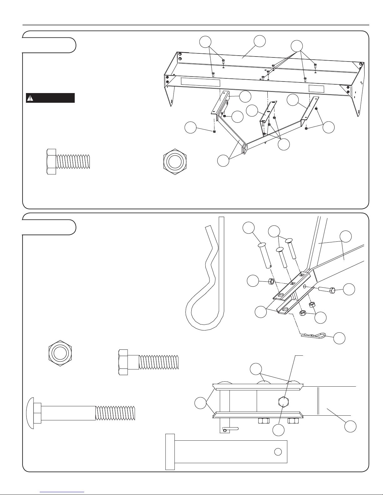
1a.AssembleSidePlates(5)to
Tray(6)asshown.
Pre-assembletheFlatWashers(24)
totheHexBolts(20).Insertthe
BoltandWasherAssemblyfromthe
insideofthetray.SecurewithNylon
LockNuts(32).
Whentighteningthebolts,forthePA-48BHmaintainadistanceof
48"to48-1/8"insidetoinsideofSidePlates(5).ForthePA-40BH
maintainadistanceof41"to41-1/8"insidetoinsideofSidePlates(5).
Figure 1 SIDE PLATE ASSEMBLY
(20)
HexHeadBolt,5/16"x3/4"
Qty.8
(8)
HexHeadBolt,5/16"x1"
Qty.4
(32)
NylonLockNut,5/16"
Qty.8
(32)
NylonLockNut,5/16"
Qty.4
(24)
FlatWasher,5/16"
Qty.8
(24)
FlatWasher,5/16"
Qty.4
2a.AssembleMountBracket(31)totheoutside
ofTowBars(7)asshown.Pre-assemblethe
FlatWashers(24)totheHexBolts(8).Insertthe
BoltandWasherAssemblyfromoutsideofthe
MountBracket.LooselytightenwithNylonLock
Nuts(32).
Figure 2 BRACKET ASSEMBLY
32
32 20
5
6
24
IMPORTANT
32
31
24
24
8
7
8
L-1762 Rev. E
7
17
2
32
29 7
21
32
18
2
29
21 7
HexBolt(21)Goes
BetweenTheTwo
CarriageBolts(29)
(20)
HexHeadBolt,5/16"x3/4"
Qty.4forPA-40BH
Qty.7forPA-48BH
(21)
HexHeadBolt,5/16"x1-1/4"
Qty.1
(32)
NylonLockNut,5/16"
Qty.4forPA-40BH
Qty.7forPA-48BH
(32)
NylonLockNut,5/16"
Qty.3
(29)
CarriageBolt,5/16"x2-1/4"
Qty.2 (17)
HitchPin
Qty.1
(18)
HairpinCotter,1/8"
Qty.1
3a.AssembleMountBrackets(31)toTray(6)as
shown.InserttheBoltsfromthetopsideofthe
Tray.LooselytightenwithNylonLockNuts(32).
IMPORTANT
Traywithlabelfacesforward.
ForPA-48BHmodelinstallCenterPlate(33)
toTray(6)asshown.InserttheBoltsfromthe
topsideoftheTray.LooselytightenwithNylon
LockNuts(32).
4a.AssembletheClevis(2)toTowbars(7)as
shown.InstallCarriageBolts(29)andNylon
LockNuts(32)ngertight.NextinstallHexBolt
(21)andNylonLockNut(32)ngertight.
4b.InsertHitchPin(17)inClevis(2)andsecure
withHairpinCotter(18).GraspHitchPinandpull
forward.
4c.Tightensecurelyallfastenersinstalledinstep
4a.Thentightensecurelyallhardwareinstalled
inSteps2through3.
Figure 3
Figure 4
TOW BAR ASSEMBLY
CLEVIS ASSEMBLY
ASSEMBLY
6
7
20 20
32
32
32
32
33
31 31
L-1762 Rev. E 8
5
10
12 15
13
12
26
26
26
26
9
15
13
28
15
20
24
(20)
HexHeadBolt,5/16"x3/4"
Qty.24forPA-40BH
Qty.32forPA-48BH
(15)
NylonBearing,3/4"I.D.
Qty.6forPA-40BH
Qty.8forPA-48BH
(28)
LockNut,5/16"
Qty.24forPA-40BH
Qty.32forPA-48BH
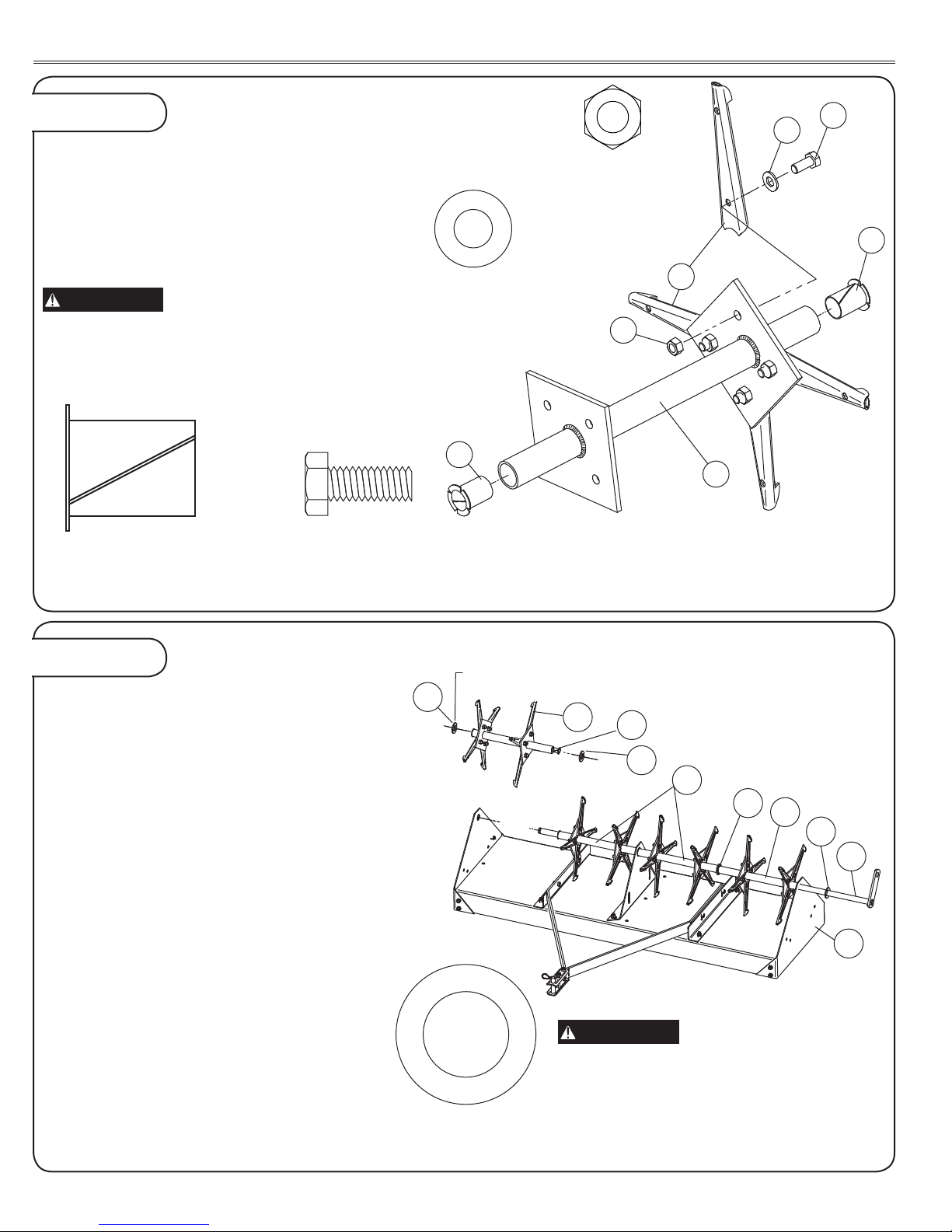
5a.AssemblePluggingSpoons(9)toeach
weldedplate(sideoppositewelds)ofalltheTube
Assemblies(12and13)asshown.ForPA-48H,
pre-assembleHexBolts(20)andFlatWashers
(24).NOTE:PA-40BHdoesnotuseFlatWashers.
InstalltheBolt(andWasherAssemblies)through
PluggingSpoonsandsecurewithLockNuts(28).
IMPORTANT
Roundedpartofspoonts
againstthetubetolockinplace.
5b.InsertaNylonBearing(15)intoeachendof
thetubeassemblies.
6a.TheEndTubeAssemblies(12)haveone
plateapproximately1-1/8"fromtheendofthe
tube.TheCenterTubeAssemblies(13)have
eachplateapproximately2-3/4"fromtheendof
thetube.
6b.PlaceaMachineryBushing(26)overAxle
Assembly(10).InsertAxleAssemblythrough
RightSidePlateandinstallinthefollowingorder:
EndTubeAssembly(12)withshorthubend•
nexttosideplate.
MachineryBushing(26).•
CenterTubeAssembly(13).•
ForPA-48BHonly:
CenterPlate(33)andthenanotherCenter•
TubeAssembly(13).
Forallmodels:
MachineryBushing(26).•
EndTubeAssembly(12)withshorthubend•
nexttosideplate.
OneormoreMachineryBushings(26)as•
requiredtoeliminateanysideplayinaxle
assembly.
OneormoreMachineryBushingsasrequiredto
eliminateanysideplayinaxleassembly.
Figure 5
Figure 6
TUBE ASSEMBLY
TINE ASSEMBLY
ASSEMBLY
(24)
FlatWasher,5/16"
Qty.32usedon
PA-48BHONLY!
(26)
MachineryBushing,3/4"
Qty.6
MakesureNylonBearings
(15)areinsideTube
Assemblies(InstalledinStep5b)
IMPORTANT

L-1762 Rev. E
9
22
25
25 30
11
23 30
32
27
16
19
14
11 32
10
7a.PushtheAxleAssembly(10)throughtheleft
sideplateasfaraspossibleandrotatesothe
holeintheatplatefacestotherearasshown.
InstalltheLiftHandleAssembly(11)withthe
weldedtubefacingout,totheAxleAssembly
(10).SecurewithHexBolt(19)andNylonLock
Nut(32).
7b.SlipHandleGrip(14)overendofLiftHandle
Assembly(11).NOTE:Soapywaterwillease
theassembly.
7a.Pre-assembleaxlebolt.InstallFlatWasher
(25)overHexBolt(22).Slideassemblythrough
wheel,noteorientation.PlaceFlatWasher(25)
andHexNut(30)onBoltandthreadonasfaras
possible,stillallowingwheeltorotatefreely.
7b.InstallthroughholesinLiftHandle(11)and
AxleAssembly(10).InstallLockWasher(23)
andHexNut(30).TighteninsideHexNutwhile
holdingHexNutnexttowheelstationary.
7c.InsertTransportPin(27)inrearholesame
sideasLiftHandleAssembly(11)asshown.
SecurewithNylonLockNut(32).
NOTE: Make sure the Axle Assembly
Flat Plate and Lift Handle Assembly are
pointing towards the rear as shown.
IMPORTANT: The wheel hub is offset to one
side. Make sure the extended offset is installed
toward plug aerator.
Figure 7
Figure 8
HANDLE ASSEMBLY
WHEEL ASSEMBLY
ASSEMBLY
(19)
HexHeadBolt,5/16"x1-1/2"
Qty.1
(27)
TransportLockPin
Qty.1
(32)
NylonLockNut,5/16"
Qty.1
(32)
NylonLockNut,5/16"
Qty.1
(14)
HandleGrip
Qty.1
(NotToScale)
(25)
FlatWasher,5/8"
Qty.4
(23)
LockWasher,5/8"
Qty.2
(30)
HexNut,5/8"
Qty.4
(22)
HexBolt,5/8"x4"
Qty.2
L-1762 Rev. E 10
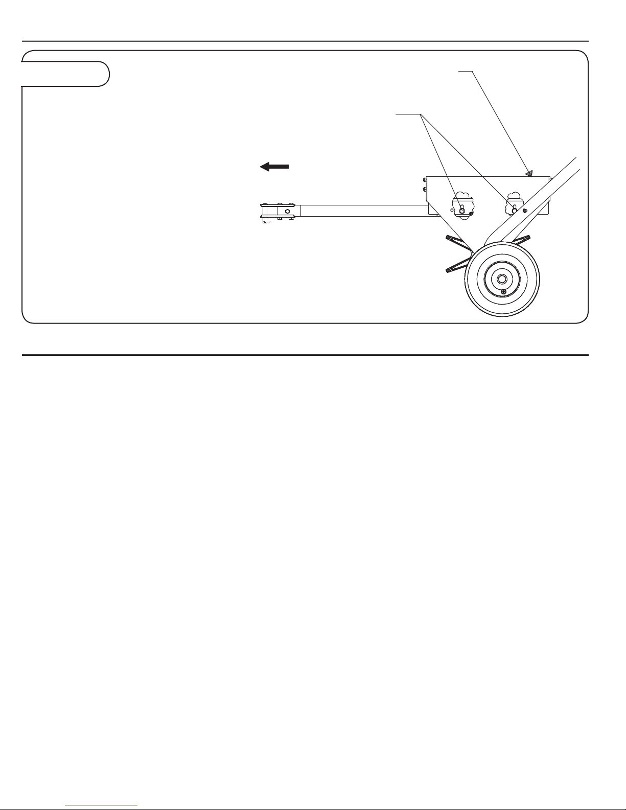
9a.ThenalstepistolevelTray(6)using
adjustmentboltsasshownhereandinstalledin
Step2.Toadjust,loosenBoltsandpositionTow
Barsuntillevel.
NOTE: The adjustment is made with the
aerator attached to the rider or lawn/garden
tractor with the wheels in transport position.
AdjustThisSurfaceToLevel
AdjustmentBolts
ToTractor
Figure 9 LEVELING
ASSEMBLY
OPERATION
CAUTION
Afterrstthirtyminutesofusecheckallfastenersfor
tightness.
Toavoiddamagetospoons,alwaysengagetransportwheels
toraisethespoonswhencrossingconcreteorasphaltwalks,
drives,orroads.
UsetheAeratoronlyonanestablishedlawn,neveronnewly
laidsod.
Toavoidpossiblepersonalinjuryand/orequipmentnever
exceedtherecommendedoperatingspeedrangeof3to5
MPH.
OnlytowAeratorbehindvehiclesforwhichitwasdesigned,
ridersandlawn/gardentractors.
Donotstand/rideonAerator,bodilyinjurycouldresult.
AlwaysdisconnectAeratorfromtractorwhencleaningor
servicingunit.
NeverexceedtheWeightTraycapacity.
DoNotattempttodisconnectAeratorfromtractorwithweight
inTray.
Whenbacking,carefullybackstraighttoavoidJack-kning,
whichcouldresultindamagetoequipment.
WHEN TO AERATE
YourAeratorshouldnotbeusedwhenlawnconditions
aretoowetortoodry.Todeterminecondition,digasmall
amountofyoursoil(aboutthreeinchesdeep):
Ifsoilappearspowderyandbrittle-itistoodry.Waituntila
laterdate,theTineswillnotpenetrateproperly.
Ifsoilappearsdamp,rollasmallamountintoaballinthe
palmofyourhand-ifitformsaball,thenitistoowet.Ideally,
thesoilshouldfallapartwhenrolledinthepalmofyour
hand.Waituntilalaterdateforsoiltodry.Ifsoilistoowet,
theTineswillnotoperateeffectivelyandyourtractorcould
loosetraction,causinglawndamage.
MOUNTING AND TRANSPORTING
Attachaeratortoyourriderorlawn/gardentractorusingPin
andHairpinCotterSupplied.
ToPlaceinTransportPosition:
PushREARWARDonLiftHandle(11)towardsTransport•
LockPininSidePlate.PullHandleOUTandmoverover
LockPin.Aeratornowrestsonwheels.
ToPlaceinOperatingPosition:
PullOUTonLiftHandle(releasingfromTransport•
LockPin)andmoveFORWARD.Aeratornowrestson
PluggingSpoons.

L-1762 Rev. E
11
MAINTENANCE
SPECIFICATIONS
SERVICE
Shouldrustdevelop,sandlightlyandthenpaintareawith
enamel.
Periodicallycheckallfastenersfortightness.
IMPORTANT:
ApplyadropoflubricatingoiltoeachNylonBearingandthe
AeratorAxlebeforeeachuse.
Topreventrustonpluggingspoons,applyalightcoatof
oilontheworkingareasofspoonsaftereachuse.Should
rustappearonanyotherpartofyourAerator,sandlightlyto
removerustandcoatlightlywithenamel.
Pluggingspoonsaremanufacturedwithspecialsteelsand
areheattreatedtoresistwearofabrasivesoil.Striking
sub-surfaceobjectscancausespoonbreakage.Contact
ourCustomerServiceDepartmenttopurchasereplacement
PluggingSpoons(Part#B-4855-10).See“GETTING
QUALITYSERVICE”.
Periodicallycheckthespoonsremoveanydebriswhich
mightbuildupandrestricttheiraction.
Aftereachuse,serviceunitasdescribedandstoreinadry
area,shieldingtinestoavoidinjury.
PA-48
MaximumTowingSpeed............................................. 5MPH
AeratorCapacity.........................................................200lbs.
EmptyWeight...............................................................90lbs.
MaximumTowingWeight............................................290lbs.
RecommendedTirePressure........................Semipneumatic
USE OF ADDITIONAL WEIGHT
Theweightrequiredtogivearecommendedpenetration
ofapproximatelytwotothreeincheswillvaryaccording
tosoiltypeandconditions.Concreteblocks,patioblocks,
sandbags,oranyothertypeofweightcanbeaddedto
AeratorTrayasrequired.Weightcanbesecuredbyusing
tiedownsthroughholesinTrayFlanges.Tiedownsarenot
furnishedwithyourunit.UsuallythreeConcreteBlockswill
besufcient,butmoreorlessweightmayberequired.
DriveyourtractortolocationtobeAerated.•
LowerAeratortoOperatingPosition.•
DrivetheTractorFORWARDapproximatelytenfeetand•
stop.
Observetheoperation-thereshouldbeaPlughole•
approximatelyeverytentotwelveinchesandnotmore
thanthreeinchesdeep.
Addorremoveweighttoobtainthiscondition.•
MAINTENANCE:
Thekeytoyearsoftrouble-freeserviceistokeepyour
Aeratorcleananddry.
NeverallowwetmaterialtoremaininTrayforextended
periodsoftime.
Occasionallycheckallmovingpartsforfreemovementand,
ifnecessary,lubricatewithoil.
PA-40
MaximumTowingSpeed............................................. 5MPH
AeratorCapacity.........................................................150lbs.
EmptyWeight...............................................................66lbs.
MaximumTowingWeight............................................216lbs.
RecommendedTirePressure........................Semipneumatic
Quality Continues With Quality Service
Weprovideaprocesstoremedyyourquestionsorproblems.
Followthestepsbelowtogetanswerstoanyquestionsyoumayhaveaboutyourproduct,ortoorderreplacementparts:
1.Refertoyourattachmentandmachineoperatormanuals.
2.InNorthAmericaandCanada,call1-877-728-8224andprovideproductserialnumberandmodelnumber.

L-1762 Rev. E
ThelimitedwarrantysetforthbelowisgivenbyBrinly-Hardy
Companywithrespecttonewmerchandisepurchasedand
usedintheUnitedStates,itspossessionsandterritories.
Brinly-HardyCompanywarrantstheproductslistedbelow
againstdefectsinmaterialandworkmanship,andwillat
itsoption,repairorreplace,freeofcharge,anypartfound
tobedefectiveinmaterialsorworkmanship.Thislimited
warrantyshallonlyapplyifthisproducthasbeenassembled,
operated,andmaintainedinaccordancewiththeOperator’s
manualfurnishedwiththeproduct,andhasnotbeensubject
tomisuse,abuse,commercialuse,neglect,accident,
impropermaintenance,alteration,vandalism,theft,re,
water,ordamagebecauseofotherperilornaturaldisaster.
NormalWearPartsorcomponentsthereofaresubject
toseparatetermsasfollows:Allnormalwearpartsor
componentfailureswillbecoveredontheproductfora
periodof90days.
Partsfoundtobedefectivewithinthewarrantyperiodwill
bereplacedatourexpense.Ourobligationunderthis
warrantyisexpresslylimitedtothereplacementorrepair,
atouroption,ofpartsfoundtobedefectiveinmaterialand
workmanship.
HOW TO OBTAIN SERVICE:Warrantypartsreplacements
areavailable,ONLYWITHPROOFOFPURCHASE,through
ourPullBehindAccessoriesCustomerServiceDepartment.
Call877-728-8224.
Thislimitedwarrantydoesnotprovidecoverageinthe
followingcases:
Routinemaintenanceitemssuchaslubricantsandlters.•
Normaldeteriorationoftheexteriornishduetouseor•
exposure.
Transportationand/orlaborcharges.•
Thewarrantydoesnotincludecommercialand/orrental•
use.
No implied warranty, including any implied warranty
of merchantability of tness for a particular purpose,
applies after the applicable period of express written
warranty above as to the part as identied below.
No other express warranty whether written or oral,
except as mentioned above, given by any person or
entity, including a dealer or retailer, with respect to
any product, shall bind Brinly-Hardy Co. During the
period of the warranty, the exclusive remedy is repair or
replacement of the product as set forth above.
The provisions as set forth in this warranty provide
the sole and exclusive remedy arising from the sale.
Brinly-Hardy Co. shall not be liable for incidental or
consequential loss or damage including, without
limitation, expenses incurred for substitute or
replacement lawn care services or for rental expenses to
temporarily replace a warranted product.
Somestatesdonotallowtheexclusionorlimitationof
incidentalorconsequentialdamages,orlimitationsonhow
longanimpliedwarrantylasts,sotheaboveexclusionsor
limitationsmaynotapplytoyou.
Duringthewarrantyperiod,theexclusiveremedyis
replacementofthepart.Innoeventshallrecoveryofany
kindbegreaterthattheamountofthepurchasepriceofthe
productsold.Alterationofsafetyfeaturesoftheproductshall
voidthiswarranty.Youassumetheriskandliabilityforloss,
damage,orinjurytoyouandyourpropertyand/ortoothers
andtheirpropertyarisingoutofthemisuseorinabilitytouse
thisproduct.
Thislimitedwarrantyshallnotextendtoanyoneotherthan
theoriginalpurchaserortothepersonforwhomitwas
purchasedasagift.
HOW STATE LAW RELATES TO THIS WARRANTY:This
limitedwarrantygivesyouspeciclegalrights,andyoumay
alsohaveotherrightswhichvaryfromstatetostate.
IMPORTANT:TheWarrantyperiodstatedbelowbeginswith
thePROOFOFPURCHASE.Withouttheproofofpurchase,
theWarrantyperiodbeginsfromthedateofmanufacture
determinedbytheserialnumbermanufacturingdate.
SPREADER WARRANTY PERIOD:
Thewarrantyperiodforthisaeratorisasfollows:Steelframe
parts–2Years.Tires,wheels,andpluggingspoonsare
normalwearitems-90days.
MANUFACTURER'S LIMITED WARRANTY FOR
Pull Behind Accessories
Other manuals for PA-40 BH
2
This manual suits for next models
1
Table of contents
Other Brinly Tiller manuals

Brinly
Brinly VV-100 User manual

Brinly
Brinly SAT2-40BH-S User manual

Brinly
Brinly SAT-40 BH User manual

Brinly
Brinly SAT2-40BH-P User manual

Brinly
Brinly PA-40 BH User manual

Brinly
Brinly SAT-401BH User manual

Brinly
Brinly DD-550 Installation and operating instructions

Brinly
Brinly SA-400BH User manual

Brinly
Brinly SAT-40 BH User manual

Brinly
Brinly CC-1000 User manual


