BRIO G10-U User guide

Tankless 2:1 RO Filtration System
Setup Manual
Model No.: ROSL500WHT
G10-U

2
Table of Contents
Safety Information .................................................................... 3
Intended Use ......................................................................... 4
Product Features ..................................................................... 4
Indicator Panel Description ..............................................................5
Product Dimensions ....................................................................5
Materials Needed ..................................................................... 5
Specifications ........................................................................ 5
Package Contents. . . . . . . . . . . . . . . . . . . . . . . . . . . . . . . . . . . . . . . . . . . . . . . . . . . . . . . . . . . . . . . . . . . . . 6
Installation ........................................................................... 6
Installation Overview....................................................................6
Connect to the Cold Water Supply ........................................................7
Make the Reverse Osmosis Waste Connections ............................................8
Install the faucet........................................................................9
Complete the Installation ...............................................................10
Operation............................................................................10
Start Up the Filtration System ...........................................................10
Start Water Purification .................................................................10
Shut Down. . . . . . . . . . . . . . . . . . . . . . . . . . . . . . . . . . . . . . . . . . . . . . . . . . . . . . . . . . . . . . . . . . . . . . . . . . . . 10
Troubleshooting ......................................................................11
Care and Maintenance.................................................................11
Filter Replacement Schedule............................................................12
Replace the Filters.....................................................................12
Flushing the Filters ....................................................................12
Warranty.............................................................................13

3
Safety Information
WARNING: To reduce risk of injury and property damage, you must read this entire guide before assembling,
installing, and operating this filtration system.
•If the power cable is damaged, do not use. Contact Customer Service for a replacement.
•Avoid storing in an area exposed to intense sunlight as this can cause damage to components.
•Do not store or expose the device in temperatures lower than 32°F (0°C). The ideal temperature
range is 39°F - 100°F (4-38°C).
•The device must be installed or relocated by a professional technician due to the risk of electric
shock and product damage.
•The best working pressure of this device ranges from 0.1 to 0.4MPa. Install a pressure increasing or
decreasing device if the water pressure is lower or higher than this level.
•For use with municipal tap water only. Not for use with well or underground water.
•Do not place magnetic devices near the device as damage could occur.
•Do not place heavy objects on the device.
•Do not allow children near the device without adult supervision.
•When cutting o the power supply, do not pull the power cord as this could cause damage.
•Do not place combustible substances near the device. Keep away from heat sources and open
flames.
•Install this device near a floor drain.
•If the device is not used for long periods of time, shut o power and turn o the 3-way ball valve.

4
Intended Use
This appliance is intended to be used in household and similar applications such as:
•Sta kitchen areas in shops, oces, and other working environments
•Farm houses
•Clients in hotels, motels, and other residential type environments
•Bed and breakfast type environments
•Catering and similar non-retail applications
This appliance is not intended for use by persons (including children) with reduced physical, sensory, or mental
capabilities, or lack of experience and knowledge, unless they have been given supervision or instruction concerning
use of the appliance by a person responsible for their safety.
Product Features
9
8
1
2
37
5
6
4
Part Description Part Description
1 Reverse Osmosis filter compartment Filtered water connection
2 PCB filter compartment Inlet water connection
Display panel 8 Tap water handle
4 Waste water connection 9 Filtered water handle
5 Purified water connection
5
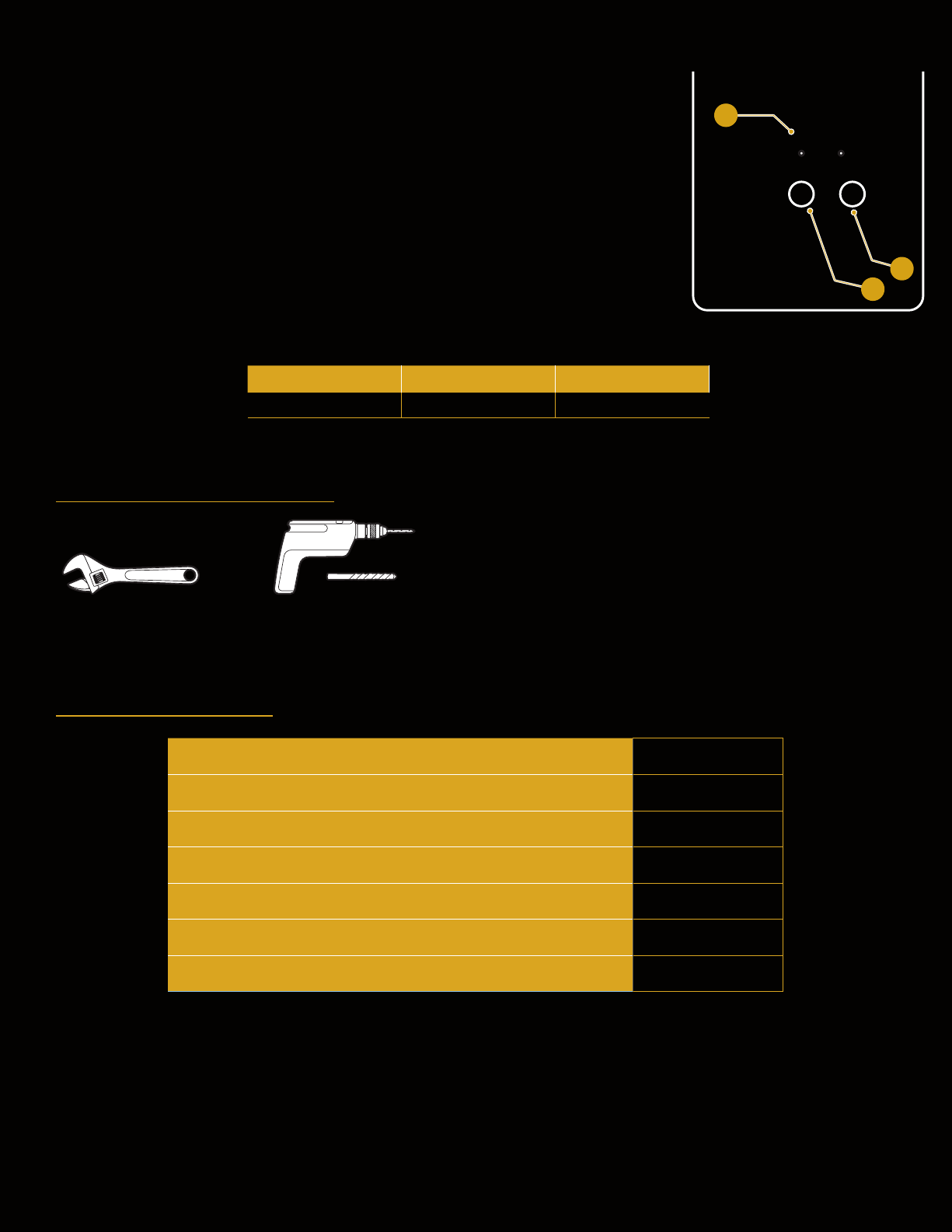
Indicator Panel Description
1. Filter indicator lights – When blinking, indicates it is time to change lters (RO or
PCB).
2. Reset button – Press to reset the system after changing lters.
3. Flush button – Press to ush newly installed lters.
Product Dimensions
Height Width Depth
42 cm (16.5 in.) 13.2 cm (5.2 in.) 46.1 cm (18.2 in.)
Materials Needed
Wrench Electric drill with 1/4 in. drill bit
Specifications
RO Water Output 7200L
Active Carbon Water Output 4000L
Rated Voltage/Frequency 24 V~/50/60Hz
Rated Total Power 80W
Purified Water Flow Rate / RO Water Output 1.75L/min
Water Inlet Pressure 0.1-0.4MPa
Critical Pressure 3.2MPa
Reset Flush
RO PCB
1
3
2

6
Package Contents
A
F
E
I
B
D
G
H
L
C
M
K
J
Part Description Quantity
A RO filtration system 1
B Faucet 1
C Power adapter 1
D Feed water adapter 1
E PCB filter 1
F RO filter 1
G Plumbers tape 1
Part Description Quantity
H Drain saddle 1
I RO water outlet tube 1
J Shut-o valve tube 1
K Faucet tubing 2
L2/8 - 3/8 in.Quick
connect 1
M 2/8 in. Quick connect 2
Installation
1. Installation Overview

7
2. Connect to the Cold Water Supply
CAUTION: DO NOT CONNECT THIS WATER LINE TO A HOT WATER SUPPLY LINE. The water supply to the unit
MUST be from the COLD WATER LINE. Using HOT WATER will severely damage your filters.
D. Turn off and then disconnect the
current cold water supply line.
E. Connect the feed water adapter (D) to
the cold water supply line.
F. Connect the cold water supply line on
top of the feed water adapter (D).
NOTE: An extra adapter nut is included
on top of the feed water
adapter (D) to attach to a 3/8in.
or 1/2 in. feed plumbing line.
D
G. Insert the shut-off valve with tube (J)
straight into the quick connector piece
of the feed water adapter (D). D
J
H. Gently tug on the tube (J) to ensure a
secure connection with the feed water
adapter (D). D
J

8
3. Make the Reverse Osmosis Waste Connections
The “RO” filter assembly requires a drain line connection to be
installed, which removes rejected water to the sewer. The drain
saddle connects the drain line from the dispenser to your drain pipe.
The drain saddle is designed to fit around a standard 1.5 in. OD (outer
diameter) drain pipe.
Always install the drain saddle before the P-trap and on a
straight vertical or horizontal section of the pipe.
To avoid clogging the drain line with debris, do not install the
drain saddle after the drain pipe meets a garbage disposal or
dishwasher drain.
To make the Reverse Osmosis (RO) drain connections:
A. Determine the location for your drain saddle (H) and then make a
mark on the drain pipe for the opening (1).
B. Use your drill and a 1/4 in. drill bit to drill a hole at the mark,
ensuring you only drill through one side of the drain pipe.
C. Find the half of the drain saddle (H) with the hole in the center,
remove the backing from the foam gasket, align the gasket with
the hole on the drain saddle (H), and stick the adhesive side of
the gasket to the drain saddle (H).
D. Position both halves of the drain saddle (H) on the drain pipe with
the saddle’s opening aligned over the drilled hole, and insert your
drill bit through the saddle (H) and drilled hole to ensure proper
alignment.
E. Secure both ends of the drain saddle (H) together using the bolts
and nuts, but do not over-tighten.
F. Connect the RO water outlet tube (I) to the drain saddle (H).
H
1
I

9
4. Install the faucet
IMPORTANT: If your sink does not have a second faucet hole, please contact a licensed professional to create
one. Do NOT attempt to drill a faucet hole yourself as this may damage the sink.
A. Ensure that you have a faucet mounting hole in your sink or sink countertop for this faucet. If you do not, create
a mounting hole no less than 1 – 1.2 in. (26 – 30 mm).
B. Remove the washer (1) and lock nut (2) from the faucet. Ensure that you leave the O-ring (3) on the faucet.
C. Attach the two 2/8 in. quick connects (M) to the large faucet post (ltered water) and the short faucet post (tap
water).
3
1
2
M
M
D. Place the faucet into the mounting hole and secure in place underneath the sink with the washer (1) and lock
nut (2).
E. Connect two faucet tubings (K) to each of the 2/8 in. quick connects (M) underneath the sink.
M
1
2
K
K
M

10
5. Complete the Installation
A. Connect the shut off valve tube (J) to
the inlet water connection (1).
B. Connect the faucet tubing (K)
connected to the 2/8 in. quick connect
(M) to the ltered water connection (2).
C. Connect the faucet tubing (K)
connected to the 2/8 in. quick connect
(M) to the puried water connection (3).
D. Connect the RO water outlet tube (I) to
the waste water connection (4).
E. Ensure all connections are made, and
proceed to the Operation section for
starting for rst time, plugging in, and
ushing.
I
43
2
1
K
J
Operation
Start Up the Filtration System
1. Ensure all water connections are completed as described in the Installation section.
2. Connect the power supply to the ltration system and then to an outlet.
The filter indicator panel turns on.
Start Water Purification
Open the faucet and the water purifier starts to produce water.
NOTE: If the faucet runs water for a long time (for 2 hours), the water purifier enters overtime protection mode.
The display screen at the side of the machine flashes, and the device is no longer able to produce water.
Unplug the power plug until the indicator turns o. Plug the device in again to clear the protection mode.
Shut Down
1. Close the shut-off valve on the tube (J).
2. Unplug the power supply.

11
Troubleshooting
Problem Probable cause Solution
The filter is generating
a light noise during
operation.
The filter can generate a light noise
during operation.
This is normal.
The water output
volume has dropped.
•The filter is jammed.
•The filter needs to be replaced.
•The ball valve or faucet is not
completely turned on.
•Flush or replace the filter.
•Replace the filter.
•Check the water inlet ball
valve, or the faucet to
ensure they are turned on
completely.
The water quality is low. •The filter needs to be replaced.
•The device was not used for a
long period of time (over 3 days).
•The quality of the source water
is low.
•Replace the filter.
•Turn on and flush the
faucet for 3-5 minutes.
•Confirm that the water
source is municipal tap
water.
There is water leakage. A component is damaged. Cut o the water and power
supply.
There is no water output
after replacing a filter.
There is an air jam. When replacing a filter, shut o
the power supply, followed by
the water supply. Then replace
the filter, the water supply, and
power supply in that order.
Care and Maintenance
•Keep this device in a dry and cool place and avoid direct sunshine.
•Use a clean, soft cloth to remove dust build-up. Do not use soap, detergent, or harsh abrasives.
•Before going out for an extended period of time, ensure the power and valve are o.
•Do not position the product in a declining, horizontal, or upturned position.
•When the water inlet temperature is as low as 32°F (0°C), turn o the water inlet valve and drain the water in the
water purifier to prevent cracks.

12
Filter Replacement Schedule
Filter Type Replacement Schedule Function
PCB Composite Filter
(PAC and Carbon)
12 months Removes mud, sand, rust, suspended
materials, residual chlorine, and
abnormal flavor from water.
RO Filter 24 months Removes up to 99% of contaminants
including arsenic, lead, fluoride,
heavy metals and more.
Replace the Filters
When the filter indicator light on the indicator panel flashes, it indicates that one of your filters needs to be replaced.
1. Disconnect the water and power supply, and nd the lter that needs to be replaced.
2. Rotate the lter rotary cover counterclockwise to remove the cover.
3. Take out the old lter and insert a new lter. Then replace the lter cover.
4. Restore power to the device and hold the Reset button for 3 seconds until the lter indicator stops ashing.
Proceed to the Flush the Filters section below.
Flushing the Filters
Press the Flush button on the panel to flush the filters. The flushing will be finished 60 seconds later. You can also
press the Flush button a second time during the 60 second flush period to stop the flushing.
NOTE: The Flush button does not work when the device is in an automatic flushing state.

13
Warranty
Brio (“Vendor”) warrants to the original purchaser of the Brio Water Filters (the “Product”), and to no other person,
that if the Product is assembled and operated in accordance with the printed instructions accompanying it, then
for a period of one (1) year from the date of purchase, all parts in the Product shall be free from defects in material
and workmanship. This Limited Warranty shall be limited to repair or replacement of parts, which prove defective
under normal use and service and which Vendor shall determine in its reasonable discretion upon examination to be
defective. To take advantage of this Limited Warranty, please follow these steps:
1.Please retain your sales slip or invoice, as Vendor may require reasonable proof of your date of purchase.
2.Contact Vendor’s Customer Service Department using the contact information listed below.
3.Return parts to Vendor, per Vendor’s instructions, at your cost and expense.
4.Upon receipt by Vendor, Vendor shall advise you in writing whether a defect covered by this Limited Warranty exists
in any returned part and whether your claim has been approved or denied.
5.Upon Vendor’s approval of your claim, Vendor will replace such defective part without charge to you.
WHAT THIS LIMITED WARRANTY DOES NOT COVER: This Limited Warranty does not cover any failures or operating
diculties of the Product due to accident, abuse, misuse, alteration, misapplication, improper installation or improper
maintenance or service by you or any third party, or failure to perform normal and routine maintenance on the Product,
as set out in the User’s Manual. In addition, this Limited Warranty does not cover damages to the finish, such as
scratches, dents, discoloration or rust after purchase.
This Limited Warranty is the only express warranty given on the Product and is in lieu of all other express warranties.
Vendor disclaims all warranties for products that are purchased from seller other than authorized retailers or
distributors. THIS LIMITED WARRANTY RESTRICTS THE DURATION OF ANY AND ALL IMPLIED WARRANTIES,
INCLUDING WITHOUT LIMITATION, THE IMPIED WARRANTY OF MERCHANTABILITY AND FITNESS FOR A
PARTICULAR PURPOSE TO THE ONE (1) YEAR TERM OF THIS LIMITED WARRANTY. UPON THE EXPIRATION OF
THE ONE (1) YEAR TERM OF THIS LIMITED WARRANTY, VENDOR DISCLAIMS ANY AND ALL IMPLIED WARRANTIES,
INCLUDING WITHOUT LIMITATION THE IMPLIED WARRANTIES OF MERCHANTABILITY AND FITNESS FOR A
PARTICULAR PURPOSE, THE PRODUCT BEING THUS SOLD AS-IS, WITH ALL FAULTS. FURTHER, VENDOR
SHALL HAVE NO LIABILITY WHATSOEVER TO PURCHASER OR ANY THIRD PARTY FOR ANY SPECIAL, INDIRECT,
PUNITIVE, INCIDENTAL, OR CONSEQUENTIAL DAMAGES. OTHER THAN THIS LIMITED WARRANTY, THERE ARE
NO WARRANTIES WHICH EXTEND BEYOND THE DESCRIPTION ON THE FACE HEREOF. Vendor assumes no
responsibility for any defects caused by third parties. This Limited Warranty gives you specific legal rights, and you
may have other rights which vary from state to state. State law may also override statements in this Limited Warranty
regarding the restriction on the duration of implied warranties. Some jurisdictions do not allow exclusion or limitation of
special, incidental or consequential damages, or limitations on how long awarranty lasts, so the above exclusion and
limitations may not apply to you.

©2022 Brio Water Technology, Inc.
Contact Us
Call: +1 844-257-4103
Table of contents
Other BRIO Water Filtration System manuals

BRIO
BRIO 3 Stage System User manual

BRIO
BRIO TROE600PRISM User guide

BRIO
BRIO FUS300R User manual

BRIO
BRIO amphora ROP100 User guide

BRIO
BRIO amphara UF100FWHT User guide

BRIO
BRIO CROS2400 User manual

BRIO
BRIO G20-U User guide

BRIO
BRIO amphora User guide

BRIO
BRIO ROSL500 User guide

BRIO
BRIO AQUUS TROE600COL User guide
Popular Water Filtration System manuals by other brands


amiad
amiad Filtomat MG112 Installation, operation and maintenance instructions

Force of Nature
Force of Nature FON-KIT-001 quick start guide

DH Instruments
DH Instruments 1-2 IN. FILTER KIT instruction sheet

GE
GE GX1S01R installation instructions

Watts
Watts E-Treat ETREATWCS Installation, operation and maintenance manual

GE
GE GNSV70RBL Owner's manual and installation instructions