BriskHeat SLCBL Series Instruction Manual

Self–Regulating Heating Cable
Installation & Maintenance
Instruction Manual
SAVE THESE INSTRUCTIONS!
Additional copies of this manual are available upon request.
You must read and understand this manual before installing, operating, or
servicing this product. Failure to understand these instructions could result
in an accident causing serious injury or death.
Keep these instructions for future reference.
Language Page
English ................................................................................................................................................................................................................................. 1
Spanish (Español) ............................................................................................................................................................................................................... 33
French (Français) ................................................................................................................................................................................................................ 65
German (Deutsch) .............................................................................................................................................................................................................. 97
Italian (Italiano) .................................................................................................................................................................................................................. 129
English
Self Regulating Heating Cable
© BriskHeat® Corporation. All rights reserved.
2
TABLE OF CONTENTS
IMPORTANT SAFETY INSTRUCTIONS ........................................................................................................................................................................... 3
PART INTENDED USE ...................................................................................................................................................................................................... 4
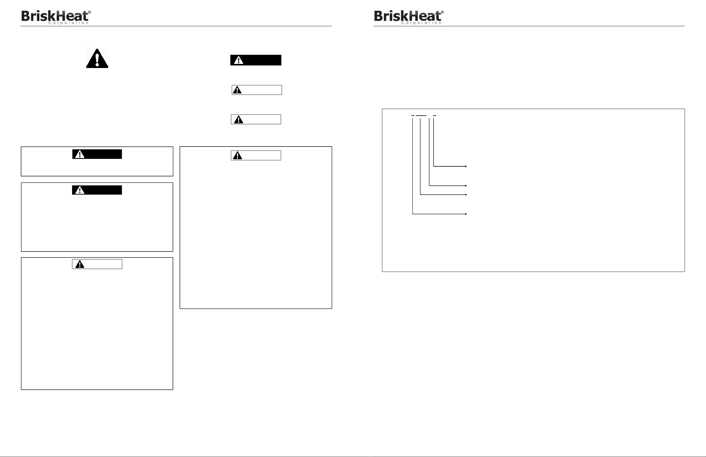
PART NUMBER MATRIX .................................................................................................................................................................................................. 4
TECHNICAL PARAMETERS ............................................................................................................................................................................................. 5
GENERAL INFORMATION ................................................................................................................................................................................................ 6
How Heating Systems Work ......................................................................................................................................................................................... 6
PRODUCT SELECTION .................................................................................................................................................................................................... 6
RECEIPT & STORAGE ..................................................................................................................................................................................................... 6
Receipt .......................................................................................................................................................................................................................... 6
Storage .......................................................................................................................................................................................................................... 6
INSTALLATION ................................................................................................................................................................................................................. 6
Scheduling .................................................................................................................................................................................................................... 7
Pre-Installation Check ................................................................................................................................................................................................... 7
Heater Handling ............................................................................................................................................................................................................ 7
Heating Cable Location ................................................................................................................................................................................................. 7
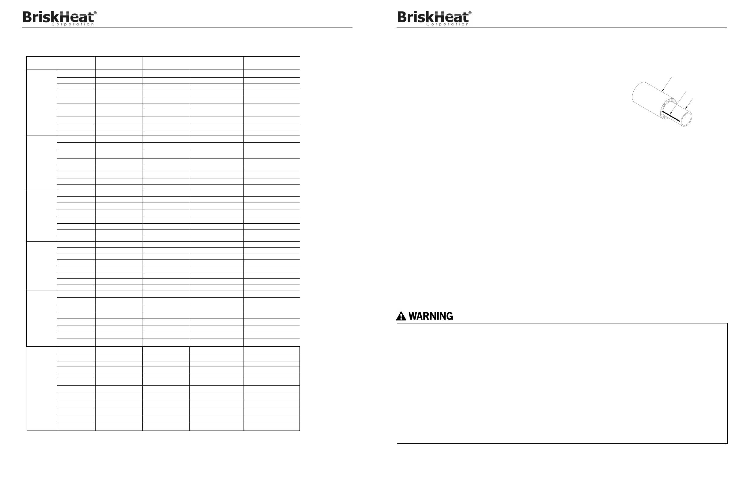
Straight Tracing ............................................................................................................................................................................................................. 7
Spiraling ........................................................................................................................................................................................................................ 8
Attachment .................................................................................................................................................................................................................... 8
Cutting the Heating Cable ............................................................................................................................................................................................. 8
Installation Details ......................................................................................................................................................................................................... 8
SYSTEM COMPONENTS ............................................................................................................................................................................................... 11
System Component Compatibility .............................................................................................................................................................................. 12
SLCBL Connection / Termination Kits ....................................................................................................................................................................... 13
SLCBL, SLMCBL, SLHCBL Connection / Termination Kits ....................................................................................................................................... 14
FM APPROVED SLCAB connection / termination kit ................................................................................................................................................. 15
FM APPROVED SLMCAB connection / termination kit .............................................................................................................................................. 15
CSA APPROVED SLCAB AND SLMCAB connection / termination kit ....................................................................................................................... 16
THERMAL INSULATION ................................................................................................................................................................................................. 17
Pre-Installation Checks ............................................................................................................................................................................................... 17
Installation ................................................................................................................................................................................................................... 17
Marking ....................................................................................................................................................................................................................... 17
THERMOSTATS & SENSORS ........................................................................................................................................................................................ 17
ELECTRICAL REQUIREMENTS ..................................................................................................................................................................................... 17
Voltage Rating............................................................................................................................................................................................................. 17
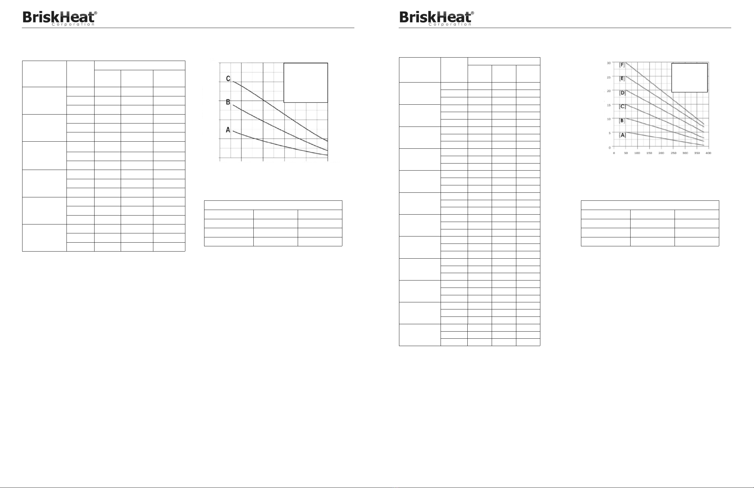
Electrical Loading ........................................................................................................................................................................................................ 18
Ground Fault Protection .............................................................................................................................................................................................. 24
Waterproofing .............................................................................................................................................................................................................. 24
TESTING ......................................................................................................................................................................................................................... 24
Recommendations ...................................................................................................................................................................................................... 24
Procedure .................................................................................................................................................................................................................... 24
START-UP ....................................................................................................................................................................................................................... 27
Heat-up Time .............................................................................................................................................................................................................. 27
Diversity Factor ........................................................................................................................................................................................................... 27
OPERATION & MAINTENANCE ..................................................................................................................................................................................... 27
System Design, Installation & Documentation ............................................................................................................................................................ 27
Preventive Maintenance.............................................................................................................................................................................................. 27
Visual Inspections ....................................................................................................................................................................................................... 27
Frequency ................................................................................................................................................................................................................... 27
Personnel Training ...................................................................................................................................................................................................... 27
Maintenance ................................................................................................................................................................................................................ 27
Piping Repairs ............................................................................................................................................................................................................. 27
DAMAGED PRODUCTS .................................................................................................................................................................................................. 28
TROUBLESHOOTING GUIDE ........................................................................................................................................................................................ 28
WARRANTY INFORMATION .......................................................................................................................................................................................... 32

Self Regulating Heating Cable
© BriskHeat® Corporation. All rights reserved.
3
IMPORTANT SAFETY INSTRUCTIONS
SAFETY ALERT SYMBOL
The symbol above is used to call your attention to instructions concerning
your personal safety. It points out important safety precautions. It means
“ATTENTION! Become Alert! Your Personal Safety is involved!” Read
the message that follows and be alert to the possibility of personal injury
or death.
WARNING
CAUTION
A person who has not read and understood all operating Instructions is
not qualified to operate this product.
DANGER
Do not immerse heater in liquid.
Keep volatile or combustible material away from heater when in
use.
Use heater only in approved locations.
Keep sharp metal objects away from heater.
Failure to observe these warnings may result in electric shock, risk of
fire, and personal injury.
DANGER
Never handle the heater while it is in operation; always disconnect
the heater from the power source and allow to cool prior to
handling.
Inspect heater and connection kits before use.
If spillage of foreign matter onto heater occurs, disconnect from
power source and clean after heater is allowed to cool.
Never operate a heater without an appropriate heat sink (device
being heated is considered a heat sink).
Do not operate heater above rated temperature value.
Fasten heater to device using approved methods only.
Do not repair damaged or faulty heaters.
Do not crush or apply severe physical stress on heater or cord
assembly.
Disconnect heater when not in use.
Failure to observe these warnings may result in personal injury or
damage to the product and/or property.
CAUTION
Immediate hazards which WILL result in severe personal injury or death.
Hazards or unsafe practices that COULD result in severe personal injury
or death.
Hazards or unsafe practices that COULD result in minor personal injury or
property damage.
End User Must Comply to the Following:
Only qualified personnel are allowed to connect the electrical
wiring.
De-energize all power circuits before installation or servicing.
Keep ends of heating devices and kit components dry before and
during installation.
The conductive layer of this heating device must be connected to a
suitable grounding/earthing terminal.
Installation in accordance with the Canadian Electrical Code Part I
(Canada) or the National Electric Code (USA) as applicable.
All electrical wiring must follow local electrical codes.
The person who performs the final installation / wiring must be
qualified for this work.
The end-user is responsible for providing a suitable disconnecting
device.
The end-user is responsible for providing suitable electrical
protection device. It is highly recommended that a ground fault
circuit breaker be used.
Failure to observe these warnings could result in severe personal injury
or death.
WARNING
DANGER
Self Regulating Heating Cable
© BriskHeat® Corporation. All rights reserved.
4
SLCBL
SLMCBL
SLHCBL
SLMCAB
SLHCAB OUTER JACKET
P = Thermoplastic; F = Fluoropolymer
TINNED VOLTAGE
120=110-COPPER BRAID
Supply 120VAC; 240=220-277 VAC
OUTPUT POWER AT 10°C
For SLHCAB: 5=5For SLCBL: 3=3W/ft; 5=5W/ft; 8=8W/ft; 10=10W/ft; 12=12W/ft;
For SLMCBL: 5=5W/ft; 10=10W/ft; 15=15W/ft; 20=20W/ft;
For SLHCBL: 5=5W/ft; 10=10W/ft; 15=15W/ft; 20=20W/ft;
For SLCAB: 3=3W/ft; 5=5W/ft; 8=8W/ft; 10=10W/ft;
For SLMCAB: 5=5W/ft; 10=10W/ft; 15=15W/ft;
W/ft; 10=10W/ft; 15=15W/ft; 20=20W/ft; 25=25W/ft; 30=30W/ft;
PART INTENDED USE
The following standard must apply for installaions in the USA.
IEEE 515.1 Installation Type A, Insulated Surfaces (including pipes)
IEEE 515.1 Installation Type B, Roof and Gutter De-Icing
IEEE 515.1 Installation Type C, Embedded Snow Melting
PART NUMBER MATRIX
X YYY B Z
SLCAB

Self Regulating Heating Cable
© BriskHeat® Corporation. All rights reserved.
5
TECHNICAL PARAMETERS
Protection Class : IP65
Power
(W/Ft) Voltage Maximum Intermittent
Exposure Temperature
Maximum
Maintain or Continuous
Exposure Temperature
SLCBL
3240 3 208V-277V 85°C 65°C
5240 5 208V-277V 85°C 65°C
8240 8 208V-277V 85°C 65°C
10240 10 208V-277V 85°C 65°C
12240 12 208V-277V 85°C 65°C
3120 3 110V-120V 85°C 65°C
5120 5 110V-120V 85°C 65°C
8120 8 110V-120V 85°C 65°C
10120 10 110V-120V 85°C 65°C
12120 12 110V-120V 85°C 65°C
SLMCBL
5240 5 208V-277V 135°C 110°C
10240 10 208V-277V 135°C 110°C
15240 15 208V-277V 135°C 110°C
20240 20 208V-277V 135°C 110°C
5120 5 110V-120V 135°C 110°C
10120 10 110V-120V 135°C 110°C
15120 15 110V-120V 135°C 110°C
20120 20 110V-120V 135°C 110°C
SCHCBL
5240 5 208V-277V 200°C 120°C
10240 10 208V-277V 200°C 120°C
15240 15 208V-277V 200°C 120°C
20240 20 208V-277V 200°C 120°C
5120 5 110V-120V 200°C 120°C
10120 10 110V-120V 200°C 120°C
15120 15 110V-120V 200°C 120°C
20120 20 110V-120V 200°C 120°C
SLCAB
3240 3 208V-277V 85°C 66°C
5240 5 208V-277V 85°C 66°C
8240 8 208V-277V 85°C 66°C
10240 10 208V-277V 85°C 66°C
3120 3 110V-120V 85°C 66°C
5120 5 110V-120V 85°C 66°C
8120 8 110V-120V 85°C 66°C
10120 10 110V-120V 85°C 66°C
SLMCAB
3240 3 208V-277V 185°C 121°C
5240 5 208V-277V 185°C 121°C
8240 8 208V-277V 185°C 121°C
10240 10 208V-277V 185°C 121°C
3120 3 110V-120V 185°C 121°C
5120 5 110V-120V 185°C 121°C
8120 8 110V-120V 185°C 121°C
10120 10 110V-120V 185°C 121°C
Part Number
SLHCAB
5240 5 208V-277V 185°C 121°C
10240 10 208V-277V 185°C 121°C
15240 15 208V-277V 185°C 121°C
20240 20 208V-277V 185°C 121°C
25240 25 110V-120V 185°C 121°C
30240 30 110V-120V 185°C 121°C
5120 5 110V-120V 185°C 121°C
10120 10 110V-120V 185°C 121°C
15120 15 110V-120V 232°C 190°C
20120 20 110V-120V 232°C 190°C
25120 25 110V-120V 232°C 190°C
30120 30 110V-120V 232°C 190°C
Self Regulating Heating Cable
© BriskHeat® Corporation. All rights reserved.
6
PRODUCT SELECTION
Consult BriskHeat factory for product selection and application engineering support.
RECEIPT & STORAGE
Receipt
Compare the materials against the shipping bill to verify receipt of proper materials.
Inspect heating cable and components for transit damage. Insulation resistance tests on each spool of cable are recommended.
If design documents (line lists or per circuit bills of material) exists, check the received materials against the lists to verify of all
needed materials. If no design documents exists, keep a receipt log of all materials received.
Storage
Cables and system components should be stored in a clean, dry area. The equipment should be protected from mechanical damage
during storage. The storage temperature range is (-40°F to 140°F) -40°C to 60°C.
INSTALLATION
While there are many acceptable ways of installing BriskHeat’s electric heating equipment, certain actions can be dangerous to
personnel and your installations. Please take care to avoid the following problems:
Do not twist the bus wires together at either end of the heating
cable. Each of these wires has a voltage or neutral applied to it;
twisting them together will cause a short circuit.
Insulate black polymer surrounding bus wires. The black compound
extruded around the bus wires is electrically conductive and should
be treated as a conductor.
All electrical connections in the system should be sealed against
moisture. To prevent electrical arcing and fire hazard, all cable
connections and electrical wiring connections should be sealed
against moisture. This includes the use of proper cable sealing kits
and the moisture proofing of all wire connections.
Do not expose heating cables to temperatures above their
maximum ratings. Higher temperatures can greatly shorten the life of
a heating cable.
Immediately replace any damaged heating cable or components.
Failure to replace any damaged components ( heating cable,
components, or thermal insulation) will result in system failure.
Classified areas (explosive dust or gases) require the use of special
electrical components. Any area having explosive gases (such as
chemical / petrochemical installations) or explosive dusts (such as
coal handling or graineries) require special cable, connection
components and control components that are approved for use in
these areas. Installation of non-approved products can result in fires
or explosions.
Installation on plastic pipe requires special considerations in
selections & installation.
GENERAL INFORMATION
This manual is designed for use with BriskHeat’s self-regulating heater products. For applications not specifically addressed, please
contact your local representative.
How Heating Systems Work
An electric heating cable system uses the electric heating cable to replace the heat that is
lost through the thermal insulation system. Replacing the lost heat allows the pipe and
product inside the pipe to be kept at a constant temperature. This will keep water from
freezing and bursting a pipe, or a liquid from setting up and plugging the pipe. Simple
systems may turn the entire system on with a contactor or switch, while others will use a
thermostat with each heating cable to control the temperature.
Figure 1
Insulation
Heater Cable
Pipe

Self Regulating Heating Cable
© BriskHeat® Corporation. All rights reserved.
7
Scheduling
The installation of the electric heat tracing needs to be coordinated with the piping, insulation, electrical and instrument groups. It should
begin only after the majority of mechanical construction is complete. Pressure testing of the pipe and installation of the instruments
should be complete prior to the start of the heating cable installation.
Pre-Installation Check
Walk the piping system and plan the routing of the heating cable. Use this check to verify completion of instrumentation and mechanical
work. All coatings (paint, etc.) must be dry before attempting the heating cable installation. Minimum installation temperature -40°F
(-40°C)
Heater Handling
Use a reel holder to roll out the heating cable.
Keep the cable strung loosely, but close to the pipe being traced. This will avoid interference with supports and other equipment.
Leave an extra 305-457mm (12-18”) of heating cable at all power connections, tee splices and end seal connections to facilitate
easy working of the connections.
ADDITIONAL HEATING CABLE IS REQUIRED ON VALVES, PIPE SUPPORTS AND OTHER EQUIMENT. See the installation
detail section for exact lengths and method of installation.
When handling the heating cable, avoid pulling it over or installing against sharp edges.
Do not kink or crush the cable, including walking on it or driving over it with equipment.
Do not exceed minimum bending radius of 0.5” (12mm) at 68°F (20°C) during installation. Colder temperatures will increase the
minimum bend radius. Use caution to avoid exceeding a safe bend radius during cold temperature installations.
Heating Cable Location
The heating cable may be installed in either straight runs or spiraled around the pipe. Spiraling is generally used when a limited number
of cable types are available.
Straight Tracing
When straight tracing is used, install the heating cable on the lower quadrant of the pipe. This helps prevent physical damage to the
heating cable from falling objects and being walked on, and promotes optional thermal transfer to materials inside the pipe.
Alternate Locations
Install heater cable at
the 4 or 8 o’clock positions
120°
Self Regulating Heating Cable
© BriskHeat® Corporation. All rights reserved.
8
Attachment
For regular installations, the heating cable may be attached with fiberglass tape. Plastic wire ties may also be used provided the plastic
has a maximum temperature rating equal to or better than the system requirements. The cable should fit snugly against the pipe and be
secured at one 305mm (12”) intervals, as shown in Figure 4.
Notes:
1. To prevent possible damage to the heating cable, do not fasten with metal straps, wire, vinyl electrical tape or duct tape.
2. Aluminum foil tape should only be used if specified by design. The foil is most often used on plastic pipe to offset the insulate effect
of the plastic. See Figure 5 above.
Cutting the Heating Cable
Do not cut the cable until it is attached to the pipe. Confirm the allowances for terminations, connections and heat sinks (valves,
support, etc.) before cutting the cable. Heating cable power is not affected by cutting to length. Protect all heating cable ends from
moisture or mechanical damage if exposed for long periods of time.
Installation Details
Heating cables should be applied in a manner to facilitate the easy removal of valves and small in-line devices without the removal of
excessive thermal insulation or having to cut the heating cable. The best way to accomplish this is to loop the cable. The amount of
heating cable installed on each valve, hanger, etc. varies with the pipe size and type of device. For installation and application
assistance, contact BriskHeat factory.
Spiraling
Spiraling increases the length of heating cable installed per foot of pipe. For spiraling application assistance, contact BriskHeat
factory.
Figure 4 Figure 5
Aluminum Foil Tape
AAT2180
PSAT36A
Fiberglass Tape
PITCH (P)
in inches

Self Regulating Heating Cable
© BriskHeat® Corporation. All rights reserved.
9
The following figures show installation details for various typical situations:
Fiberglass Tape
Heater Cable
Valve
Typical installation method
(may vary for different valve shapes)
Figure 7
Figure 8
Fiberglass Tape
Heater Cable
Heater cable should be
positioned on the outside
radius of all elbows on 51mm
(2”) diameter pipes & larger.
Fiberglass Tape
Heater Cable
Elbow
Flange
Self Regulating Heating Cable
© BriskHeat® Corporation. All rights reserved.
10
Figure 9
Heater Cable
Hanger Support
Fiberglass Tape
Bar Hanger
Bar Hanger
Heater Cable
Do not clamp heater
Figure 10
Pipe Shoe Support
Shoe Support
Heater Cable
Heater Cable
Fiberglass Tape
Fiberglass Tape
Pipe Shoe Support
Side View
Bottom View

Self Regulating Heating Cable
© BriskHeat® Corporation. All rights reserved.
11
SYSTEM COMPONENTS
Only BriskHeat’s approved termination, connection and splice kits should be used. Failure to do so will void warranties and agency
approvals. Installation instructions in each component kit should be followed regarding heating cable preparation and assembly. Make
end seals (terminations) and splice connections before making the power connections. It is recommended that all heating cables be
tagged as they are installed with a discrete circuit number. This will facilitate identification, components needed and electrical wiring
during later phases of the installation. Power connection kits utilize an adapter plate kit for installation on instrument tubing and tanks.
Installation instructions for mounting are included in each kit.
Note: Heating cable power connections and end seals are required for each heating cable. Heating cable splices, tees, and
thermostats are used as needed.
Figure 11
Power Connection Kit
Tee Splice Heat Sink Pipe Clamps
In-line Splice
End Seal
Heater Cable Loop
Heater Cable
Fiberglass Tape
Insulation
Connecting bus wires together will create an electrical short.
Self Regulating Heating Cable
© BriskHeat® Corporation. All rights reserved.
12
SLCBL SLMCBL SLHCBL SLMCAB SLHCAB
SLCBLUC Yes
Ordinary Locations and
Roof & Gutter No No No No
SLCBLUC-GF Yes
Ordinary Locations and
Roof & Gutter No No No No
SLCBLKC Yes
Ordinary Locations and
Roof & Gutter No No No No
SLCBLSK Yes
Ordinary Locations and
Roof & Gutter No No No No
PTBO-GET Yes
Hazardous Locations Yes Yes No No
JHE-GET Yes
Hazardous Locations Yes Yes No No
JHS-GET Yes
Hazardous Locations Yes Yes No No
JHT-GET Yes
Hazardous Locations Yes Yes No No
SLCABUC No No No No No
SLCABSK No No No No No
SLCABKC No No No No No
SLMCABUC No No No Yes
Ordinary and
Hazardous Locations No
SLMCABKC No No No Yes
Ordinary and
Hazardous Locations No
SLCABUC-CSA-M No No No Yes
Ordinary and
Hazardous Locations No
SLCABEND-CSA-2 No No No Yes
Ordinary and
Hazardous Locations No
ROOFKIT No No No No No
ROOFENDKIT No No No No No
SLCABPWP-H No No No No Yes
Ordinary and
Hazardous Locations
SLCABKC-H No No No No Yes
Ordinary and
Hazardous Locations
SLCAB
No
No
No
No
No
No
No
No
Yes
Ordinary and
Hazardous Locations
Yes
Ordinary and
Hazardous Locations
Yes
Ordinary and
Hazardous Locations
No
No
Yes
Ordinary and
Hazardous Locations
Yes
Ordinary and
Hazardous Locations
Yes
SLCAB-BP only
Yes
SLCAB-BP only
No
No
System Component Compatibility

Self Regulating Heating Cable
© BriskHeat® Corporation. All rights reserved.
13
SLCBL Connection / Termination Kits
For use in ordinary locations with SLCBL cable only (UL approved).
For use in roof & gutter snow melting & de-icing applications with SLCBL cable only (UL approved).
Kit Contents:
2
2
1
1
1
Heat-trace warning labels
De-icing snow melt caution labels
Standoff pipe mounting bracket
Lock nut
1/2”NPT Seal fitting with strain relief and grommet
3
1
1
2
1
1
Wire nuts
Black heat-shrink tube 1/2” x 1” (13mm x 25mm)
Green/Yellow heat-shrink tube 1/4” x 6” (6mm x 15cm)
Black heat-shrink tubes 1/8” x 5-1/2” (3mm x 14cm)
Sealing gasket
End seal
Enough to complete:
One input power connection and one end seal termination.
NOTE: Junction box and pipe strap sold seperately. Requires UL Listed junction box suitable for the location with a clearance hole for 1/2” conduit or
1/2” NPT thread hub. For heating cable with no outer-jacket (Type -B only), a metallic junction box must be used to ensure proper grounding.
SLCBLUC: SLCBL Power Connection Kit
Approvals valid only when used with appropriate heating cable and installation accessories,
and installed in accordance with all applicable instructions, codes, and regulations.
Kit Contents:
2
2
1
2
2
2
1
Heat-trace warning labels
De-icing snow melt caution labels
Cloth tape
Mastic strips
Clamp ties
Crimp-on insulated terminals
Crimp-on non-insulated barrel
1
1
2
1
1
1
Heat-shrink tube 3/4” x 8” (19mm x 20cm)
Heat-shrink tube 3/4” x 5” (19mm x 13cm)
Heat-shrink tubes 1/8” x 1” (3mm x 25mm)
Heat-shrink tube 1/2” x 1” (13mm x 25mm)
Heat-shrink tube 5/16” x 1-1/2” (8mm x 38mm)
Ground fault device with 120V 3-Prong NEMA 5-15 plug
Enough to complete:
One ground-fault protection power input power connection.
SLCBLUC-GF: Ground Fault Power Connection Kit
Kit Contents:
2
2
Heat-shrink caps
Heat-shrink tubes 3/4” x 5” (19mm x 13cm)
2 Woven braid sleeves 1/2” x 4” (13mm x 10cm)
Enough to complete:
Two end seal terminations.
SLCBLKC: SLCBL End Seal Kit
Kit Contents:
1
3
1
5
Clamp tie
Cable ties
Cloth tape
Matic strips
1
3
6
2
Black heat-shrink tube 1” x 8” (25mm x 20cm)
Black heat-shrink tubes 1/2” x 1” (13mm x 25mm)
Black heat-shrink tubes 1/8” x 1” (3mm x 25mm)
Crimp-on insulated terminals
2
1
1
1
Heat-shrink caps
Heat-shrink tube
Crimp-on non-insulated barrel
End seal
Enough to complete:
One splice connection and one end seal termination or one tee connection and one end seal termination.
NOTE: This kit does not complete an input power connection
SLCBLSK: SLCBL Splice and Tee Kit
Self Regulating Heating Cable
© BriskHeat® Corporation. All rights reserved.
14
SLCBL, SLMCBL, SLHCBL Connection / Termination Kits
For use in Hazardous Area Locations with SLCBL (BP, BF) cable only (CSA approved).
For use in non-hazardous area locations with SLCBL, SLMCBL, SLHCBL cable (non-CSA approved).
JHE-GET: SLCBL, SLMCBL, SLHCBL Low-Profile End Seal Kit
Kit Contents:
1
1
3
End seal housing
Watertight sealing grommet
Pressure seal end with screws
Enough to complete:
One low-profile end seal termination.
Kit Contents:
1
2
2
2
2
In-line splice housing
Watertight sealing gaskets
Housing covers with screws
Watertight sealing grommets
Pressure seal ends with screws
Enough to complete:
One low-profile splice termination.
JHS-GET: SLCBL, SLMCBL, SLHCBL Low-Profile Splice Connection Kit
JHT-GET: SLCBL, SLMCBL, SLHCBL Low-Profile Tee Connection Kit
Kit Contents:
1
2
2
3
3
Tee splice housing
Watertight sealing gaskets
Housing covers with screws
Watertight sealing grommets
Pressure seal ends with screws
Enough to complete:
One low-profile tee connection.
NOTE: This kit does not complete an input power connection.
Hazardous (Classified) Locations
Class I, Division 2, Groups A, B, C, D
Class II, Division 2, Groups E, F, G
Class III
Approvals valid only when used with appropriate heating cable and installation
accessories, and installed in accordance with all applicable instructions, codes, and
regulations.
Kit Contents:
1
1
2
1
1
Octagon junction box with terminal power connections
Pipe standoff mounting bracket
Pipe Straps
Lock nut
Sealing gasket
1
2
1
2
2
M25x1.5 IP68 Seal fitting
Watertight sealing grommets
Watertight sealing plug
Green/Yellow heat-shrink tube 1/4” x 6” (6mm x 15cm)
Black heat-shrink tube 1/8” x 5-1/2” (3mm x 14cm)
Enough to complete:
One input power connection.
PTBO-GET: SLCBL, SLMCBL, SLHCBL Power Connection Kit With Octagon Enclosure

Self Regulating Heating Cable
© BriskHeat® Corporation. All rights reserved.
15
FM APPROVED SLCAB connection / termination kit
KITS USAGE
SLCABUC: SLCAB Universal Connection Kit. FM approved.
1
2
4
2
2
2
1
1
1
1
1
3/4” (19mm) NPT pipe standoff
Ring terminals
Large, Insulated crimp connectors
Small, Insulated crimp connectors
Pipe straps (for up to 6” (152mm) IPS pipe)
Heat sink end caps
6” (152mm) shrink sleeve
3 oz. (89ml) tube of RTV sealant
Roll of fiberglass tape
Caution label
Ground screw
Ordinary Locations
Hazardous (Classified) Locations
Class I, Division 2, Group B, C, D
Class II, Division 2, Group F, G
Class III, Division 2
Approvals valid only when used with appropriate heating cable and installation
accessories, and installed in accordance with all applicable instructions, codes, and
regulations.
Enough to complete:
Two end terminations and one input connection, or one input power splice
NOTE: Requires a 3/4” (19mm) NPT junction box
SLCABSK: SLCABSK Kit. FM approved.
20
20
10
1
Large yellow crimp connectors
Large blue crimp connectors
Heat shrink tubes
3 oz, (89ml) tube of RTV sealant
Enough to complete:
Ten input power connections, or Ten tee splices
10 Heat shrink tube Enough to complete:
Ten end terminations
SLCABKC: SLCAB End Seal Kit. FM approved.
KITS USAGE
SLMCABUC: SLMCAB Universal Connection Kit. FM approved.
1
2
3
2
2
2
1
1
1
1
3/4” (19mm) NPT pipe standoff
Ring terminals
Large, crimp connectors
Small, crimp connectors
Pipe straps (for up to 6” (152mm) IPS pipe)
End boots
3 oz. (89ml) tube of RTV sealant
Roll of fiberglass tape
Caution label
Ground screw
Ordinary Locations
Hazardous (Classified Locations
Class I, Division 2, Group B, C, D
Class II, Division 2, Group F, G
Class III, Division 2
Approvals valid only when used wir appropriate heating cable and installation
accessories, and installed in accordance with all applicable instructions, codes, and
regulations.
Enough to complete:
Two end terminations and one input connection, or one input power splice, or one tee
splice
NOTE: Requries a 3/4” (19mm) NPT junctiuon box
10
4
1
End boots
Roll of fiberglass tape
3 oz, (89ml( tube of RTV sealant))
Enough to complete:
Ten end terminations
SLMCABKC: SLMCAB End Seal Kit. FM approved.
FM APPROVED SLMCAB connection / termination kit
Self Regulating Heating Cable
© BriskHeat® Corporation. All rights reserved.
16
CSA APPROVED SLCAB AND SLMCAB connection / termination kit
KITS USAGE
SLCABUC-CSA-M: SLCAB and SLMCAB Universal Connection Kit. CSA approved.
1
1
2
1
1
1
1
1
1
1
1
1
1
1
Connector body
Connector cap
Connector gland washers
Grommet
Termination boot
Stain relief grip
Standoff bracket
Locknut
Termination block
Roll of fiberglass tape
Silicone sealant
Pipe strap (for 2” to 6” (51 to 152mm) O.D.pipes)
Ring tongue terminal
End seal kit
Approvals valid only when used with appropriate heating cable and installation
accessories, and installed in accordance with all applicable instructions, codes, and
regulations.
*2E approved for 3 watts/ft and 5 watts/ft only
Enough to complete:
One input connection and one end termination. Splices and power input splices can be
made using two kits
NOTE: Requires a 3/4” (19mm) NPT junction box
1
1
1
End cap
Clamp
Sealant
Enough to complete:
One end termination
SLCABEND-CSA-2: SLCAB and SLMCAB End Seal Kit. CSA approved.
Ordinary Locations 130-03 (-G,-W, -S)
Hazardous (Classified) Locations
Class I, Division 1† and 2, Groups B, C, D
Class II, Division 1† and 2, Groups E, F, G
Class III, Division 1† and 2
3, 5, 8 W/ft T6
10 W/ft T5
CSA APPROVED SLHCAB connection / termination kit
KITS USAGE
SLCABPWP-H : SLHCAB Power Connection Kit for pipes. CSA approved.
1
1
2
1
1
1
2
1
1
1
1
1
Base
Top
Junction Box
Sealing Grommet (large hole)
Sealing Grommet (small hole)
Sealing Gasket
Shrink Tubes 1/8" x 51/2" (black)
Shrink Tube 1/4" x 51/2" (green/yellow)
Shrink Tube 1/2" x 11/2" (white)
Lock Ring
Adaptor (for installation on pipe smaller than 1")
Stainless Steel Tie Wire
Approvals valid only when used with appropriate heating cable and installation
accessories, and installed in accordance with all applicable instructions, codes, and
regulations.
Enough to complete:
One input connection and one end termination. Splices and power input splices can be
made using two kits
NOTE: Requires a 3/4” (19mm) NPT junction box
1
1
1
End cap
Clamp
Sealant
Enough to complete:
One end termination
SLCABKC-H: SLHAB End Seal Kit. CSA approved.
Ordinary Locations 130-03 (-G,-W, -S)
Hazardous (Classified) Locations
Class I, Division 1† and 2, Groups B, C, D
Class II, Division 1† and 2, Groups E, F, G
Class III, Division 1† and 2
3, 5, 8 W/ft T6
10 W/ft T5
†CI/D1 approval for BF only. Contact a BriskHeat representative for information on Division I hazardous location systems.

Self Regulating Heating Cable
© BriskHeat® Corporation. All rights reserved.
17
Marking
Install “Electric Trace” signs on alternate sides of the piping at regular intervals, as a warning to maintenance personnel. Permanently mark the outside of the insulation
lagging with the location of heating cable components. This will facilitate maintenance in the event of a problem.
THERMOSTATS & SENSORS
Temperature sensitive applications will require the use of a thermostatic control. Selection of the proper thermostat must consider voltage and amperage ratings of the device
as well as the suitability of housing for the environment (explosion proof, rain tight, corrosion resistance, etc.). Thermostat housing should be mounted as close as possible to
the power connection kit. It may be attached to the power connection kit provided code requirements are met with regard to conduit connections seals, etc. To sense the
coolest air temperature, ambient (air sensing) thermostats should be mounted in the shade when possible. When using pipe-sensing thermostats, the bulb (sensor) should be
mounted on the opposite side of the pipe from the heater, or as far away as is practical. This will allow the thermostat to sense the actual pipe temperature and not be
influenced by the heater temperature. Mount the bulb at least three (3) feet from the closest heat sink if possible.
Moisture inside the enclosure will cause both corrosion and electrical shorting problems. The potential for this type of problem can be greatly reduced by:
Proper sealing of all enclosures openings.
Keeping enclosure cover closed and secured as mush as possible during installation sequence.
Proper closing and sealing of the cover to prevent leaking into the housing.
Use of a moisture proofing/electrical spray (aerosol) sealant on thermostat and electrical connections (including all metal parts) at completion of installation.
Connection and use of space heater if thermostat is so equipped. Do not de-energize space heater during summer months.
ELECTRICAL REQUIREMENTS
Voltage Rating
Verify that the heating cable voltage rating is suitable for the service being used. 240 volt rated cables may be used from 208 to 277 volts, with an accompanying change in
power output.
THERMAL INSULATION
Pre-Installation Checks
Inspect the heating cable and components for correct installation and possible damage. In particular, verify that:
The proper extra amount of heating cable has been installed at each valve, flange, pipe support, etc. and that it is free from physical nicks, tears or gouging. Additional
cable beyond the specified amount at a heat sink is not a problem due to the self-regulation effect of the heating cable.
Connections, splices and end seals are correctly installed, including cable seals at power connection enclosures.
Ensure insulation is properly rated fir the maximum edxposure temperature of the heated system.
Installation
Check the thermal insulation type and thickness against the design criteria. Changes in insulation type or thickness may require a different wattage heating cable. Verify that
all pipe work, including wall penetrations, fittings, etc. has been completely insulated.
Check the system to verify that:
Insulation is not wet from rainfall prior to the application of waterproofing.
Lap joints on vertical piping are properly overlapped - higher piece lapped over the top of lower piece.
Band seals are used at lap joints to prevent the ingress of water.
All penetrations of lagging (valve stems, hanger rods, etc.) are properly water proofed.
Irregular shaped items (i.e. pumps, etc.) are properly waterproofed.
To minimize potential damage to the heating cable, install the insulation as soon as possible. It is recommended that another insulation resistance (megger) test be done after
the insulation has been installed to verify that the heating cable was not damaged during the insulation installation.
Self Regulating Heating Cable
© BriskHeat® Corporation. All rights reserved.
18
Maximum Circuit Length in Feet Vs. Circuit Breaker Size
Heat Cable
Type
Circuit
Breaker
Size
Start-up Temperature
50°F
(10°C)
0°F
(-18°C)
-20°F
(-29°C)
SLCAB3120
15 amp 300 200 180
20 amp - 270 230
30 amp - 330 330
SLCAB3240
15 amp 660 410 360
20 amp - 560 480
30 amp - 660 660
SLCAB5120
15 amp 230 150 130
20 amp 270 200 175
30 amp - 270 260
SLCAB5240
15 amp 460 300 260
20 amp 540 400 345
30 amp - 540 520
SLCAB8120
15 amp 150 95 85
20 amp 200 125 100
30 amp 210 190 170
40 amp - 210 210
SLCAB8240
15 amp 295 195 170
20 amp 390 250 225
30 amp 420 375 340
40 amp - 420 420
SLCAB10120
15 amp 115 70 60
20 amp 150 95 85
30 amp 180 145 120
40 amp - 180 165
SLCAB10240
15 amp 230 150 130
20 amp 305 200 175
30 amp 360 300 260
40 amp - 360 360
Voltage Adjustment Factors
Power Adjustment Factor
Product Type 208 VAC 277 VAC
SLCAB3240 0.75 1.28
SLCAB5240 0.86 1.16
SLCAB8240 0.91 1.10
SLCAB10240 0.93 1.08
Electrical Loading
Size over-current protective devices shown in Figure 12 and 13. If devices are other than standard thermal magnetic circuit breakers,
consult factory.
(For installation in USA) All appropriatedly rated circuit breakers must be identified using a reference label indicating which branch
circuit supplies the circuits to the series heating cable sets.
SLCAB
Figure 12
Power Output, W/ft
Pipe Temperature, °F(°C)
12
10
8
6
4
2
0
Heat Output (Watts per Foot)
D = 10 W/FT
C = 8 W/FT
B = 5 W/FT
A = 3 W/FT
0 (-3) 50 (10) 70 (21) 90 (32) 110 (43) 130 (54) 150 (66)

Self Regulating Heating Cable
© BriskHeat® Corporation. All rights reserved.
19
Maximum Circuit Length in Feet Vs. Circuit Breaker Size
Heat Cable Type
Circuit
Breaker
Size
Start-up Temperature
50°F
(10°C)
0°F
(-18°C)
-20°F
(-29°C)
SLMCAB5120
15 amp 150 135 130
20 amp 200 180 170
30 amp 240 220 210
SLMCAB5240
15 amp 250 230 220
20 amp 330 305 295
30 amp 480 440 420
SLMCAB10120
15 amp 90 85 80
20 amp 120 110 105
30 amp 180 165 160
SLMCAB10240
15 amp 140 130 125
20 amp 190 175 170
30 amp 280 260 250
SLMCAB15120
15 amp 70 65 60
20 amp 90 85 80
30 amp 130 125 120
SLMCAB15240
15 amp 100 95 90
20 amp 135 125 120
30 amp 200 185 180
Voltage Adjustment Factors
Power Adjustment Factor
Product Type 208 VAC 277 VAC
SLMCAB5240 0.78 1.25
SLMCAB10240 0.86 1.16
SLMCAB15240 0.92 1.09
SLMCAB
Figure 13
Heat Output (Watts per Foot)
Power Output, W/ft
C = 8 W/FT
B = 5 W/FT
A = 3 W/FT
20
16
12
8
4
0
0 (-18) 50 (10) 100 (38) 150 (66) 200 (93) 250 (121)
Pipe Temperature, °F(°C)
Self Regulating Heating Cable
© BriskHeat® Corporation. All rights reserved.
20
Maximum Circuit Length in Feet Vs. Circuit Breaker Size
Voltage Adjustment Factors
Watt/ft Output Adjustment Factor
Product Type 208 VAC 277 VAC
SLHCAB10240 0.88 1.14
SLHCAB20240 0.94 1.08
SLHCAB30240 0.99 1.01
SLHCAB
Figure 14
Heat Cable Type
Circuit
Breaker
Size
Start-up Temperature
50°F
(10°C)
-0°F
(-20°C)
-50°F
(-45°C)
SLHCAB5120
10 amp 240 140 115
15 amp 320 220 190
20 amp 330 265 225
SLHCAB5240
10 amp 485 275 232
15 amp 643 436 377
20 amp 660 530 449
SLHCAB10120
10 amp 162 105 80
15 amp 249 170 127
20 amp 265 215 164
SLHCAB10240
10 amp 324 209 160
15 amp 498 337 255
20 amp 530 433 328
SLHCAB15120
10 amp 123 54 52
15 amp 177 90 82
20 amp 200 115 103
SLHCAB15240
20 amp 406 229 206
30 amp 420 350 275
40 amp 420 350 320
SLHCAB20120
10 amp 75 45 35
15 amp 121 65 55
20 amp 150 80 70
SLHCAB20240
20 amp 295 164 141
30 amp 315 215 170
40 amp 360 215 215
SLHCAB25120
10 amp 55 30 25
15 amp 90 45 45
20 amp 115 60 50
SLHCAB25240
20 amp 229 124 98
30 amp 229 158 120
40 amp 240 158 158
SLHCAB30120
20 amp 229 124 98
30 amp 229 158 120
40 amp 240 158 158
SLHCAB30240
20 amp 229 124 98
30 amp 229 158 120
40 amp 240 158 158
F = 30 W/FT
E = 25 W/FT
D = 20 W/FT
C = 15 W/FT
B = 10 W/FT
A = 5 W/FT
Heat Output (Watts per Foot)
Power Output, W/ft
Pipe Temperature, °F(°C)

Self Regulating Heating Cable
© BriskHeat® Corporation. All rights reserved.
21
Maximum Circuit Length in Feet Vs. Circuit Breaker Size
Heat Cable
Type
Circuit
Breaker
Size
Start-up Temperature
50°F
(10°C)
32°F
(0°C)
-4°F
(-20°C)
-40°F
(-40°C)
SLCBL3120
10 amp 240 200 140 115
15 amp 320 300 220 190
20 amp 330 320 265 225
30 amp 330 320 280 265
40 amp 330 320 280 265
SLCBL3240
10 amp 485 396 275 232
15 amp 643 606 436 377
20 amp 660 643 530 449
30 amp 660 643 557 530
40 amp 660 643 557 530
SLCBL5120
10 amp 162 135 105 80
15 amp 249 215 170 127
20 amp 265 252 215 164
30 amp 265 252 240 200
40 amp 265 252 240 200
SLCBL5240
10 amp 324 269 209 160
15 amp 498 429 337 255
20 amp 530 505 433 328
30 amp 530 505 480 400
40 amp 530 505 480 400
SLCBL8120
10 amp 123 100 54 52
15 amp 177 145 90 82
20 amp 200 180 115 103
30 amp 210 180 175 135
40 amp 210 180 175 160
SLCBL8240
10 amp 246 203 108 104
15 amp 354 291 183 164
20 amp 406 360 229 206
30 amp 420 360 350 275
40 amp 420 360 350 320
SLCBL10120
10 amp 75 55 45 35
15 amp 121 85 65 55
20 amp 150 105 80 70
30 amp 155 120 105 85
40 amp 180 155 105 105
SLCBL10240
10 amp 147 111 85 68
15 amp 242 177 131 114
20 amp 295 216 164 141
30 amp 315 246 215 170
40 amp 360 315 215 215
SLCBL12120
10 amp 55 40 30 25
15 amp 90 60 45 45
20 amp 115 80 60 50
30 amp 115 90 80 60
40 amp 120 105 80 80
10 amp 111 78 59 49
15 amp 183 124 91 85
20 amp 229 160 124 98
30 amp 229 180 158 120
40 amp 240 210 158 158
SLCBL10240
Voltage Adjustment Factors
Product Type 208 VAC 277 VAC
SLCBL5240 0.85 1.12
SLCBL8240 0.89 1.08
SLCBL10240 0.89 1.08
SLCBL12240 0.89 1.08
Watt/ft Output Adjustment Factor
SLCBL3240 0.82 1.13
Product Type 208 VAC 277 VAC
SLCBL5240 0.94 1.09
SLCBL8240 0.92 1.11
SLCBL10240 0.92 1.11
SLCBL12240 0.92 1.11
Max Circuit Length Adjustment Factor
SLCBL3240 0.96 1.08
SLCBL
Heat Output (Watts per Foot)
Power Output, W/ft
21
18
15
12
9
0
E = 12 W/FT
D = 10 W/FT
C = 8 W/FT
B = 5 W/FT
A = 3 W/FT
32(0) 50(10) 68(20) 86(30) 104(40) 122(50) 140(60) 158(70)
Pipe Temperature, °F(°C)
E
D
C
B
A
Figure 15
Self Regulating Heating Cable
© BriskHeat® Corporation. All rights reserved.
22
Maximum Circuit Length in Feet Vs. Circuit Breaker Size
Heat Cable
Type
Circuit
Breaker
Size
Start-up Temperature
50°F
(10°C)
32°F
(0°C)
-4°F
(-20°C)
-40°F
(-40°C)
SLMCBL5120
10 amp 110 80 - -
15 amp 133 105 98 90
20 amp 195 160 148 138
30 amp 210 195 170 165
40 amp 210 195 183 180
SLMCBL5240
10 amp 220 160 145 135
15 amp 265 210 195 180
20 amp 390 320 295 275
30 amp 420 390 365 360
40 amp 420 390 340 330
SLMCBL10120
10 amp 75 73 - -
15 amp 100 95 80 70
20 amp 133 148 125 100
30 amp 174 180 156 130
40 amp 174 175 156 140
SLMCBL10240
10 amp 150 145 121 114
15 amp 200 190 160 140
20 amp 265 295 249 200
30 amp 347 360 311 280
40 amp 347 350 311 260
SLMCBL15120
10 amp 57 51 - -
15 amp 94 87 57 54
20 amp 120 108 71 69
30 amp 154 133 80 80
40 amp 154 133 90 87
SLMCBL15240
10 amp 114 101 68 65
15 amp 187 173 114 108
20 amp 239 216 141 137
30 amp 308 265 180 173
40 amp 308 265 160 160
SLMCBL20120
10 amp 51 41 - -
15 amp 82 72 51 49
20 amp 102 90 67 61
30 amp 131 115 84 74
40 amp 150 128 110 95
10 amp 101 82 62 55
15 amp 164 144 101 98
20 amp 203 180 134 121
30 amp 262 229 167 147
40 amp 300 255 220 190
SLMCBL20240
Voltage Adjustment Factors
Product Type 208 VAC 277 VAC
SLMCBL5240 0.84 1.20
SLMCBL10240 0.85 1.18
SLMCBL15240 0.91 1.09
SLMCBL20240 0.90 1.07
Watt/ft Output Adjustment Factor
Product Type 208 VAC 277 VAC
SLMCBL5240 0.95 1.04
SLMCBL10240 0.94 1.06
SLMCBL15240 0.91 1.10
SLMCBL20240 0.91 1.11
Max Circuit Length Adjustment Factor
SLMCBL
Figure 16
Heat Output (Watts per Foot)
Power Output, W/ft
24
21
18
15
12
9
6
3
0
A
B
C
D
D = 20 W/FT
C = 15 W/FT
B = 10 W/FT
A = 5 W/FT
32(0) 68(20) 104(40) 140(60) 176(80) 212(100)
Pipe Temperature, °F(°C)

Self Regulating Heating Cable
© BriskHeat® Corporation. All rights reserved.
23
Maximum Circuit Length in Feet Vs. Circuit Breaker Size
Heat Cable
Type
Circuit
Breaker
Size
Start-up Temperature
50°F
(10°C)
32°F
(0°C)
-4°F
(-20°C)
-40°F
(-40°C)
SLHCBL5120
10 amp 120 110 105 90
15 amp 180 175 158 143
20 amp 240 215 190 180
30 amp 259 245 240 225
40 amp 266 255 250 240
SLHCBL5240
10 amp 240 220 210 180
15 amp 360 350 315 285
20 amp 479 430 380 360
30 amp 518 490 480 450
40 amp 531 510 500 480
SLHCBL10120
10 amp 73 69 65 58
15 amp 118 110 98 88
20 amp 148 140 130 118
30 amp 220 200 182 175
40 amp 255 240 220 230
SLHCBL10240
10 amp 146 138 130 116
15 amp 236 220 195 175
20 amp 295 280 260 235
30 amp 440 400 364 350
40 amp 510 480 440 460
SLHCBL15120
10 amp 50 47 42 40
15 amp 75 65 63 60
20 amp 100 90 83 80
30 amp 143 135 125 120
40 amp 190 175 168 160
SLHCBL15240
10 amp 100 93 83 80
15 amp 150 130 125 120
20 amp 200 180 165 160
30 amp 285 270 250 240
40 amp 380 350 335 320
SLHCBL20120
10 amp 39 33 34 32
15 amp 58 55 50 48
20 amp 75 71 68 63
30 amp 115 105 100 95
40 amp 153 143 133 125
10 amp 77 70 67 63
15 amp 115 110 100 95
20 amp 150 142 135 125
30 amp 230 210 200 190
40 amp 306 286 265 250
SLHCBL20240
Voltage Adjustment Factors
Product Type 208 VAC 277 VAC
SLHCBL5240 0.87 1.07
SLHCBL10240 0.88 1.08
SLHCBL15240 0.88 1.08
SLHCBL20240 0.86 1.07
Watt/ft Output Adjustment Factor
Product Type 208 VAC 277 VAC
SLHCBL5240 0.99 1.08
SLHCBL10240 0.99 1.06
SLHCBL15240 0.98 1.06
SLHCBL20240 1.00 1.08
Max Circuit Length Adjustment Factor
SLHCBL
Figure 17
Heat Output (Watts per Foot)
Power Output, W/ft
21
18
15
12
9
6
3
0
A
B
C
D D = 20 W/FT
C = 15 W/FT
B = 10 W/FT
A = 5 W/FT
32(0) 68(20) 104(40) 140(60) 176(80) 212(100) 248(120)
Pipe Temperature, °F(°C)
Self Regulating Heating Cable
© BriskHeat® Corporation. All rights reserved.
24
Ground Fault Protection
Ground fault circuit breakers are required on all heater constructions per the National Electric Code. Typically, 30ma trip devices are
required due to the capacitive leakage of the heating cable construction.
Waterproofing
Moisture penetration of the electrical system is the single largest source of problems in a heating cable system installation. Therefore,
particular care must be given to the proper sealing of all electrical connections and splices. Heating cable sealing kits will provide a
proper seal for the heating cable itself, when used per kit instructions. All other electrical connections (heater to power wiring,
thermostat connections, panel and breaker connections, etc.) should be sealed or moisture proofed in some fashion. Either mastic
shrink tube or an aerosol electrical insulative sealant should be used on all connections to reduce any moisture penetration. The
sealant will also reduce the potential for corrosion on exposed metal parts.
TESTING
Recommendations
Electrical tests are recommended at specific points in the receipt and installation of the heating cable. This periodical testing is
designed to prevent the expenditure of wasted labor in the event of damage to the product. Installation costs of the cable and thermal
insulation are much greater that the heating cable. Quick identification of any heating cable damage is the most economic approach to
an installation. An insulation resistance test is recommended at the following point of the installation process:
UPON RECEIPT of the heating cable
BEFORE thermal INSULATION installation
IMMEDIATELY AFTER thermal insulation installation
As part of a PERIODIC MAINTENANCE program
Procedure
The insulation resistance test is used to check for damage to extruded jackets. Connections for the megger are made as shown in
Figures 18 & 19.
Note: Test should use at least a 500 VDC megger. Do not use a megger with an excess of 2500 VDC. Minimum acceptable readings
should be 20 megohms per circuit, regardless of length.
Figure 18
500 VDC
MEGGER
FOR HEATING CABLES WITH BRAID
Test from heating cable bus to braid

Self Regulating Heating Cable
© BriskHeat® Corporation. All rights reserved.
25
FOR HEATING CABLES WITH BRAID AND OUTER
JACKET
Test A - (solid lines) from heating cable bus wires to braid.
Test B - (dotted lines) from braid to metal pipe.
Figure 19
A record should be kept of the readings taken from the time the cable is first installed on the pipe. A history of the insulation resistance
reading can be helpful in spotting moisture ingress into the electrical system (by seeing a gradual decline in the insulation resistance or
physical damage to the heating cable (sharp decline in the insulation resistance). A sample record for this is shown in Figure 20. (See
following page)
500 VDC
MEGGER
Self Regulating Heating Cable
© BriskHeat® Corporation. All rights reserved.
26
PERIODIC INSPECTION RECORD FORM
Figure 20
Periodic Inspection Record Form
The Periodic Inspection record Form may be used in one of two ways:
1. One sheet per circuit - The results of periodic tests of a single circuit are posted in vertical columns, beginning on the left and
working toward the right. This allows easy comparison of test values for up to seven test sequences on an individual circuit.
2. One circuit per column - Test data for a single test sequence on as many as seven circuits can be recorded on a single sheet.
Freeze Protection Circuits -
Perform these checks as season requiring use approaches.
Temperature Maintenance Circuits -
Perform these checks at least twice per year.
Visual inspection inside connection box Initial
corrosion, moisture, etc. Date
Damage or cracks (leaks) in insulation Initial
seals at valves, hangers, pumps, etc. Date
Heating cable properly connected and Initial
grounded. heating cable and connections
insulated from connection box. Date
Thermostat checked for moisture, corrosion, Set Point
set point, switch operation, and capillary Initial
damage Date
Megger tests performed at power Reading
connection with both bus wires disconnected Initial
from power wiring. Date
Circuit voltage at power connection. Reading
Circuit amperage after 5 minutes Reading
Pipe temperature at time amps were measured. Reading
Watts/Ft.
Volts x Amps = w/ft. Initial
feet Date
All connections, boxes, and thermostats Initial
have been resealed. Date
End seals, covered splices and tees marked Initial
On insulation cladding. Date
Remarks & Comments
Maintenance Checks for _______________________________ Month _______________________ Year_________________
Circuit Number
Heater Type
Circuit Length
BRISKHEAT PERIOD INSPECTION RECORD

Self Regulating Heating Cable
© BriskHeat® Corporation. All rights reserved.
27
START-UP
Heat-up Time
Heat-up capacity (the ability to heat the pipe and it’s contents rapidly) is not normally designed into the system. Cold start-ups should
allow adequate time for the pipe to come up to temperature.
Diversity Factor
If the electrical supply capability is limited, then a diversity factor may be used in a cold start situation (trying to start the entire system up
in very cold weather). This is accomplished by staggering the initial turn on of the heating cable circuits to allow the inrush currents to
occur in a sequential fashion rather than all at once.
OPERATION & MAINTENANCE
System Design, Installation & Documentation
The heating cable system must be properly designed, installed and documented. This documentation should at least include line lists and
location identification documentation. As built installation drawings provided the optimum maintenance tool. Test records should also be
considered as part of the system documentation requirements. See Figure 20 & 21.
Preventive Maintenance
A preventive maintenance program is needed which will encompass both visual and electrical checks of the system. These should be
done not only before initial operation of the system, but also on a scheduled basis. The checks should also be done after any
maintenance has been performed.
Visual Inspections
Thermal insulation - check weatherproofing for damage, missing seals, cracks or gaps in caulking and mastic coatings, damaged or
missing lagging. When damage does exist, the insulation will need to be repaired or replaced, and then resealed. WET INSULATION
HAS POOR INSULATING PROPERTIES, THEREFORE THE INSULATION MUST BE KEPT DRY. If insulation has been damaged,
check the heating cable for damage - replace the damaged section.
Inspect junction boxes, connection boxes and thermostats for corrosion, moisture or foreign matter.
Tightness of electrical connections, proper electrical insulation of heating cable wires, adequacy of moisture seal on electrical
connections and that a minimum of one (1) inch of electrically insulated heater extends above the grounding connection. No strands
of the ground braid should extend above this connection.
Check all thermostats or sensor capillary leads to verify they are tied back and shielded from physical damage.
Verify all enclosure, connection box, etc. covers are properly closed and that the thermostat is switching off and on by measuring
current flow in the circuit when the unit switches on. Reset the knob to the proper temperature after completion of the test.
Frequency
Inspections should be made prior to the start of the freeze season on freeze protection systems. Process maintenance systems should
be checked on a frequent base, at least twice a year.
Personnel Training
Qualified maintenance personnel must be used to maintain the system. It is recommended that periodic training programs be utilized to
assist in keeping maintenance personnel up to date on equipment and procedures.
Maintenance
The heating cables will not require any maintenance. Mechanical temperature controls should be sprayed with a moisture repellent/
corrosion inhibitor once a year on all metal parts.
Piping Repairs
Disconnect the electrical connection for the heating cable and protect it from mechanical or thermal damage during the repair. Check the
heating cable installation after the repairs per established procedures. Replace and water seal the thermal insulation system.
Self Regulating Heating Cable
© BriskHeat® Corporation. All rights reserved.
28
DAMAGED PRODUCTS
Do not attempt to repair a damaged heating cable - replace the entire section. Fault currents will often destroy the bus wire / core ma-
terial interface between the damaged portion and the voltage supply end of the circuit.
Replace the damaged heating cable immediately. Moisture migration into the good section of the heating cable may cause electrical
shorting in that cable after repair of the damaged section.
Any product exposed to fire or flame should be removed from service immediately and replaced. Further fire damage could result if
energized.
TROUBLESHOOTING GUIDE
PROBABLE CAUSE CORRECTION
A. Circuit Breaker
Trips
(Standard)
1. Circuit breaker undersized 1, 2, 3. Re-establish what the current loads are going to be
and resize the breakers.*
2. Circuit oversized
3. Start-up at too low temp.
4. Defective circuit breaker 4. Replace circuit breaker.
5. Connection and/or splices may be
shorting out.
5, 6. Locate and repair incorrect connections, splices, or
damaged sections of heating cable.
** Megger per installation instructions.
6. Physical damage to the heating
cable may be causing a short.
7. Wires connected at end seal. 7. Disconnect wires and perform a current check for
possible other damage.
B. Circuit Breaker
Trips (Ground
Leakage Type)
1. All of section A. 1. All of section A.
2. Excessive moisture in connection
boxes or splices.
2. Dry out and re-seal connections and splices. Megger
per Installation Instructions (20 megohms min.) Work
on connections outside the thermal insulation first,
going to the below insulation connections and seals
after the others have been eliminated.
3. Nick or cut in heater or power feed
wire with moisture present.
3. Locate and repair or replace damaged heating cable
or power wire.**
SYMPTOMS
* Check to see if existing power wire sizing is compatible with larger sized breakers.
** To locate shorting problems, follow these steps:
1. Visually inspect the power connections and splices that are outside of the thermal insulation for proper installation.
2. Check around the valves, pumps, and any area where there may have been maintenance work done, for visual indications of
damage.
3. Look for crushed or damaged insulation lagging along the pipe.
4. Inspect heating cable splices under the thermal insulation.
5. If you have not located the problem by now, you will have to isolate one section of the heating cable at a time until you
determine the general area of damage. First, isolate by disconnecting any tees or splices then remove insulation from that area
until the specific damage is found. For long runs of cable, it may be necessary to cut the cable in half to isolate the shorted
section.

Self Regulating Heating Cable
© BriskHeat® Corporation. All rights reserved.
29
SYMPTOMS PROBABLE CAUSE CORRECTION
Power output is zero or
lower than rated.
***
1. Low or no input voltage.
2. Circuit is shorter than design shows.
a. Splices or tees may not have been
connected.
b. Heating cable may have been
severed.
3. Improper crimping causing a high resistance
connection.
4. Control thermostat is wired in the opened
position.
5. Pipe is at an elevated temperature.
6. Heating cable has been exposed to
excessive moisture.
7. Heating cable has been exposed to
excessive temperatures.
1. Repair electrical supply lines and equipment.
2. Check routing and length of heating cable
(use “as-builts”), and recalculate power
requirements.
a. Connect and recheck the power.
b. Locate and repair the damaged heating
cable. Recheck the power.
3. Re-crimp using correct procedure.
4. Rewire in the normally closed position.
5. Check pipe temperature and recalculate the
output.***
6,7. Replace the heating cable.
Power output appears
correct but pipe
temperatures are
below design value.
1. Insulation is wet.
2. Insufficient heating cable was used on
valves, supports, and other heat sinks.
3. Thermostat was set incorrectly.
4. There are thermal design inconsistencies.
1. Remove and replace with dry insulation and
insure proper weatherproofing.
2. Splice in additional heating cable but do not
go over maximum circuit length.
3. Reset the thermostat.
4. Check with the local or factory representatives
for design conditions. Modify as
recommended.
C.
D.
*** The power output on lower resistance heating cables is temperature sensitive and requires a special procedure to determine it’s
value.
1. Check the pipe temperature under the thermal insulation.
2. Allow heating cable to stabilize for 10 minutes and then measure the current.
3. Calculate the power (watts / ft.) of the heating cable by multiplying the current by the input voltage and dividing by the actual
circuit length
4. Compare this measured value to the power output curves for the heating cable at the measured pipe temperature. If the
heating cable’s actual output is substantially below the theoretical output, the bus wire interface with the core has been
damaged by the fault current and the cable must be replaced. This is not a highly accurate method of analysis, so use
discretion in comparing theoretical and actual values.
I xV Watts
Ft. Ft.
=
Self Regulating Heating Cable
© BriskHeat® Corporation. All rights reserved.
30
HEAT TRACE INSTALLATION RECORD
1. Circuit No._______________________________
2. Receiving Documentation Date _____________________________________________
Item DESIGN ACTUAL
A. Cable Type _______________________ _______________________
B. Cable Length _______________________ _______________________
3. Receiving Testing Date _____________________________________________
A. Check for physical damage O.K. ___________________ Damage ________________
B. Continuity Check
Check for continuity between power leads. O.K. ___________________ Open ___________________
C. 500VDC min., 2500VDC recommended,
megger check between leads and
sheath, 20 megohms min. Megohms _________________________________________
D. Lot No. No. ______________________________________________
4. Post Installation Testing Date _____________________________________________
A. Continuity Check
Check for continuity between cold leads. O.K. ___________________ Open ___________________
B. 500VDC min., 2500VDC recommended,
megger check between leads and
sheath, 20 megohms min. Megohms _________________________________________
C. Visually Check Cable Installation Prior to
Release for Thermal Insulation. Visual Check O.K. __________________________________
5. Final Testing and Commissioning Date _____________________________________________
A. Circuit approved for testing by client. Approved _________________________________________
B. 500VDC min., 2500 VDC recommended,
megger check between leads and
sheath, 20 megohms min. Megohms _________________________________________
C. Energized Testing
(all test data to be within 10% of design data) DESIGN ACTUAL
1. Circuit Voltage _______________________ _______________________
2. Initial Current _______________________ _______________________
3. Current after 15 minutes of operation _______________________ _______________________
4. Current after 30 minutes of operation _______________________ _______________________
5. Pipe temperature _______________________ _______________________
6. Circuit Acceptance _______________________ _______________________
This circuit has been tested and documented in accordance with the above itemized data. This circuit by:
Contractor_____________________________________________________________ Date_____________________
The Heat Trace Installation Record can be used to monitor the initial installation and check out process. This form can be used in
conjunction with the Periodic Inspection Record shown in Figure 20.
Figure 21

Self Regulating Heating Cable
© BriskHeat® Corporation. All rights reserved.
31
NOTE
Self Regulating Heating Cable
© BriskHeat® Corporation. All rights reserved.
32
WARRANTY INFORMATION
BriskHeat warrants to the original purchaser of this product for the period of eighteen (18) months from date of shipment or twelve (12)
months from date of installation, whichever comes first. BriskHeat’s obligation and the exclusive remedy under this warranty shall be
limited to the repair or replacement, at BriskHeat’s option, of any parts of the product which may prove defective under prescribed use
and service following BriskHeat’s examination, is determined by BriskHeat to be defective. The complete details of the warranty can be
found online at www.briskheat.com or by contacting us at 1-800-848-7673 (toll free, U.S. / Canada) or 1-614-294-3376 (Worldwide).
Corporate Headquarters:
4800 Hilton Corporate Dr.
Columbus, OH 43232, U.S.A.
Toll Free: 800-848-7673
Phone: 614-294-3376
Fax: 614-294-3807
Email: bhtsales1@briskheat.com
Europe:
P.O. Box 420124
44275 Dortmund, Germany

Cable calefactor autorregulado
Manual de instrucciones de
instalación y mantenimiento
¡CONSERVE ESTAS INSTRUCCIONES!
Pueden obtenerse copias adicionales de este manual a pedido.
Debe leer y comprender este manual antes de instalar, hacer funcionar o
reparar este producto. La incapacidad de comprender estas instrucciones
podría causar un accidente con lesiones graves o la muerte.
Guarde estas instrucciones para futura referencia.
Spanish (Español)
Cable calefactor autorregulado
© BriskHeat® Corporation. Todos los derechos reservados.
34
ÍNDICE
INSTRUCCIONES IMPORTANTES DE SEGURIDAD ................................................................................................................................................... 35
USO PREVISTO DE LAS PIEZAS ................................................................................................................................................................................. 36
MATRIZ DE NÚMEROS DE PIEZA ................................................................................................................................................................................ 36
PARÁMETROS TÉCNICOS ........................................................................................................................................................................................... 37
INFORMACIÓN GENERAL ............................................................................................................................................................................................ 38
Cómo funcionan los sistemas de calefacción ............................................................................................................................................................ 38
SELECCIÓN DE PRODUCTOS ..................................................................................................................................................................................... 38
RECEPCIÓN Y ALMACENAMIENTO ............................................................................................................................................................................ 38
Recepción .................................................................................................................................................................................................................. 38
Almacenamiento: ....................................................................................................................................................................................................... 38
INSTALACIÓN ................................................................................................................................................................................................................ 38
Programación ............................................................................................................................................................................................................. 39
Verificación previa a la instalación ............................................................................................................................................................................. 39
Manejo del calefactor ................................................................................................................................................................................................. 39
Ubicación del cable calefactor ................................................................................................................................................................................... 39
Aplicación de calor recta ............................................................................................................................................................................................ 39
Aplicación en espiral .................................................................................................................................................................................................. 40
Fijación ....................................................................................................................................................................................................................... 40
Corte del cable calefactor .......................................................................................................................................................................................... 40
Detalles de instalación ............................................................................................................................................................................................... 40
COMPONENTES DEL SISTEMA ................................................................................................................................................................................... 43
Compatibilidad de componentes del sistema ............................................................................................................................................................ 44
SLCBL - Kits de conexión y terminación .................................................................................................................................................................... 45
SLCBL, SLMCBL, SLHCBL - Kits de conexión y terminación ................................................................................................................................... 46
SLCAB APROBADO POR FM - Kits de conexión y terminación ............................................................................................................................... 47
SLMCAB APROBADO POR FM - Kits de conexión y terminación ............................................................................................................................ 47
SLCAB Y SLMCAB APROBADOS POR CSA - Kits de conexión y terminación ....................................................................................................... 48
AISLAMIENTO TÉRMICO .............................................................................................................................................................................................. 49
Verificaciones previas a la instalación ....................................................................................................................................................................... 49
Instalación .................................................................................................................................................................................................................. 49
Marcación ................................................................................................................................................................................................................... 49
TERMOSTATOS Y SENSORES .................................................................................................................................................................................... 49
REQUISITOS ELÉCTRICOS .......................................................................................................................................................................................... 49
Especificación de tensión ........................................................................................................................................................................................... 49
Carga eléctrica ........................................................................................................................................................................................................... 50
Protección contra fallas a tierra .................................................................................................................................................................................. 56
Impermeabilización .................................................................................................................................................................................................... 56
PRUEBAS ....................................................................................................................................................................................................................... 56
Recomendaciones ...................................................................................................................................................................................................... 56
Procedimiento ............................................................................................................................................................................................................ 56
PUESTA EN MARCHA ................................................................................................................................................................................................... 59
Tiempo de calentamiento ........................................................................................................................................................................................... 59
Factor de diversidad ................................................................................................................................................................................................... 59
OPERACIÓN Y MANTENIMIENTO ................................................................................................................................................................................ 59
Diseño, instalación y documentación del sistema ..................................................................................................................................................... 59
Mantenimiento preventivo .......................................................................................................................................................................................... 59
Inspecciones visuales ................................................................................................................................................................................................ 59
Frecuencia ................................................................................................................................................................................................................. 59
Capacitación del personal .......................................................................................................................................................................................... 59
Mantenimiento ............................................................................................................................................................................................................ 59
Reparaciones de tuberías .......................................................................................................................................................................................... 59
PRODUCTOS DAÑADOS .............................................................................................................................................................................................. 60
GUÍA DE LOCALIZACIÓN DE FALLAS ......................................................................................................................................................................... 60
INFORMACIÓN DE GARANTÍA ..................................................................................................................................................................................... 64

Cable calefactor autorregulado
© BriskHeat® Corporation. Todos los derechos reservados.
35
INSTRUCCIONES IMPORTANTES DE SEGURIDAD
SÍMBOLO DE ALERTA DE SEGURIDAD
El símbolo precedente se utiliza para llamarle la atención sobre
instrucciones concernientes a su seguridad personal. Sirve para señalar
precauciones de seguridad importantes. Significa '¡ATENCIÓN!
¡Manténgase alerta! ¡Está en juego su seguridad personal!' Lea el
mensaje que sigue a continuación y manténgase alerta ante la posibilidad
de lesiones personales o la muerte.
ADVERTENCIA
PRECAUCIÓN
PELIGRO
Una persona que no haya leído y comprendido las instrucciones de
operación no está calificada para operar este producto.
PELIGRO
No sumerja el calefactor en líquido.
Mantenga los materiales volátiles o combustibles lejos del
calefactor cuando esté en uso.
Utilice el calefactor solamente en los lugares aprobados.
Mantenga los objetos metálicos aguzados lejos del calefactor.
No prestar atención a estas advertencias puede resultar en un choque
eléctrico, riesgo de incendio y lesiones personales.
PELIGRO
No maneje nunca el calefactor cuando esté en operación;
desconecte siempre el calefactor de la fuente de alimentación y
espere a que se enfríe antes de manejarlo.
Inspeccione el calefactor y los kits de conexión antes del uso.
Si se produce un derrame de material extraño sobre el calefactor,
desconéctelo de la fuente de alimentación y límpielo después de
que se haya enfriado.
No opere nunca un calefactor sin un disipador de calor apropiado
(el dispositivo que se está calentando se considera un disipador de
calor).
No opere nunca un calefactor por encima del valor de temperature
nominal.
Sujete el calefactor al dispositivo solo mediante métodos
aprobados.
No repare calefactores dañados o defectuosos.
No aplaste ni aplique presión física severa sobre el conjunto de
calefactor o de cables de alimentación.
Desconecte el calefactor cuando no se esté utilizando.
No prestar atención a estas advertencias puede resultar en lesiones
personales o daños al producto y otros daños materiales.
Riesgos inmediatos que CAUSARÁN lesiones personales graves o la
muerte.
Riesgos o prácticas inseguras que PODRÍAN CAUSAR lesiones
personales graves o la muerte.
Riesgos o prácticas inseguras que PODRÍAN CAUSAR lesiones
personales menores o daños materiales.
El usuario final debe cumplir con lo siguiente:
Solo el personal calificado está autorizado para conectar el
cableado eléctrico.
Desenergice todos los circuitos de alimentación eléctrica antes de
la instalación o el servicio.
Mantenga secos los extremos de los dispositivos calefactores y los
componentes del kit antes y durante la instalación.
La capa conductora de este dispositivo calefactor debe conectarse
a un terminal de conexión a masa/tierra adecuado.
Realice la instalación de acuerdo con el Código Eléctrico
Canadinese, parte I (Canadá) o el Código Eléctrico Nacional (EE.
UU.) según corresponda.
Todo el cableado eléctrico debe observar los códigos eléctricos
locales.
La persona que realiza la instalación / conexionado final debe estar
calificada para este trabajo.
El usuario final es responsable de proporcionar un dispositivo de
desconexión adecuado.
El usuario final es responsable de proporcionar un dispositivo de
protección eléctrica adecuado. Se recomienda muy especialmente
utilizar un interruptor automático de protección contra fallas a tierra.
Si no se siguen estas advertencias podrían producirse graves lesiones
personales o la muerte.
ADVERTENCIA
PRECAUCIÓN
Cable calefactor autorregulado
© BriskHeat® Corporation. Todos los derechos reservados.
36
USO PREVISTO DE LAS PIEZAS
Se deben aplicar para las instalaciones en los EE. UU. las siguientes normas:
IEEE 515.1 Instalación Tipo A, Superficies aisladas (incluidas tuberías)
IEEE 515.1 Instalación Tipo B, Descongelación de techos y canaletas
IEEE 515.1 Instalación Tipo C, Sistemas de fusión de nieve empotrados
MATRIZ DE NÚMEROS DE PIEZA
SLCBL
SLMCBL
SLHCBL
SLCAB
SLMCAB
SLHCAB ENVOLTURA EXTERIOR
P = Termoplástico; F = Fluoropolímero
TRENZA DE COBRE ESTAÑADO
TENSIÓN DE ALIMENTACIÓN
120=110-120VAC; 240=220-277 VAC
POTENCIA DE SALIDA A 10°C
For SLCBL: 3=3W/ft; 5=5W/ft; 8=8W/ft; 10=10W/ft; 12=12W/ft;
For SLMCBL: 5=5W/ft; 10=10W/ft; 15=15W/ft; 20=20W/ft;
For SLHCBL: 5=5W/ft; 10=10W/ft; 15=15W/ft; 20=20W/ft;
For SLCAB: 3=3W/ft; 5=5W/ft; 8=8W/ft; 10=10W/ft;
For SLMCAB: 5=5W/ft; 10=10W/ft; 15=15W/ft;
For SLHCAB: 5=5W/ft; 10=10W/ft; 15=15W/ft; 20=20W/ft; 25=25W/ft; 30=30W/ft;
X YYY B Z

Cable calefactor autorregulado
© BriskHeat® Corporation. Todos los derechos reservados.
37
PARÁMETROS TÉCNICOS
Clase de protección: IP65
Potencia
(W/pie) Tensión Temperatura de exposición
intermitente máxima Temperatura de exposición
mantenida o continua máxima
SLCBL
3240 3 208V-277V 85°C 65°C
5240 5 208V-277V 85°C 65°C
8240 8 208V-277V 85°C 65°C
10240 10 208V-277V 85°C 65°C
12240 12 208V-277V 85°C 65°C
3120 3 110V-120V 85°C 65°C
5120 5 110V-120V 85°C 65°C
8120 8 110V-120V 85°C 65°C
10120 10 110V-120V 85°C 65°C
12120 12 110V-120V 85°C 65°C
SLMCBL
5240 5 208V-277V 135°C 110°C
10240 10 208V-277V 135°C 110°C
15240 15 208V-277V 135°C 110°C
20240 20 208V-277V 135°C 110°C
5120 5 110V-120V 135°C 110°C
10120 10 110V-120V 135°C 110°C
15120 15 110V-120V 135°C 110°C
20120 20 110V-120V 135°C 110°C
SCHCBL
5240 5 208V-277V 200°C 120°C
10240 10 208V-277V 200°C 120°C
15240 15 208V-277V 200°C 120°C
20240 20 208V-277V 200°C 120°C
5120 5 110V-120V 200°C 120°C
10120 10 110V-120V 200°C 120°C
15120 15 110V-120V 200°C 120°C
20120 20 110V-120V 200°C 120°C
SLCAB
3240 3 208V-277V 85°C 66°C
5240 5 208V-277V 85°C 66°C
8240 8 208V-277V 85°C 66°C
10240 10 208V-277V 85°C 66°C
3120 3 110V-120V 85°C 66°C
5120 5 110V-120V 85°C 66°C
8120 8 110V-120V 85°C 66°C
10120 10 110V-120V 85°C 66°C
SLMCAB
3240 3 208V-277V 185°C 121°C
5240 5 208V-277V 185°C 121°C
8240 8 208V-277V 185°C 121°C
10240 10 208V-277V 185°C 121°C
3120 3 110V-120V 185°C 121°C
5120 5 110V-120V 185°C 121°C
8120 8 110V-120V 185°C 121°C
10120 10 110V-120V 185°C 121°C
Número de pieza
SLHCAB
5240 5 208V-277V 185°C 121°C
10240 10 208V-277V 185°C 121°C
15240 15 208V-277V 185°C 121°C
20240 20 208V-277V 185°C 121°C
25240 25 110V-120V 185°C 121°C
30240 30 110V-120V 185°C 121°C
5120 5 110V-120V 185°C 121°C
10120 10 110V-120V 185°C 121°C
15120 15 110V-120V 232°C 190°C
20120 20 110V-120V 232°C 190°C
25120 25 110V-120V 232°C 190°C
30120 30 110V-120V 232°C 190°C
Cable calefactor autorregulado
© BriskHeat® Corporation. Todos los derechos reservados.
38
INSTALACIÓN
INFORMACIÓN GENERAL
Este manual está destinado a su uso con los productos de la línea de calefactores autorregulados de BriskHeat. Para aplicaciones que
no estén tratadas específicamente, contacte con su representante local.
Cómo funcionan los sistemas de calefacción
Un sistema de cable calefactor eléctrico utiliza el cable para reemplazar el calor que se
pierde a través del sistema de aislamiento térmico. El reemplazo del calor perdido permite
que la tubería y el producto que está dentro de ella se mantengan a una temperature
constante. Esto evitará que el agua se congele y haga estallar una tubería, o que un
líquido se solidifique y la tapone. En los sistemas simples puede energizarse todo el
sistema con un contactor o un interruptor, mientras que otros utilizan un termostato con
cada cable calefactor para controlar la temperatura.
SELECCIÓN DE PRODUCTOS
Por todo lo relativo a selección de productos y asistencia en ingeniería de aplicaciones, consulte con la fábrica de BriskHeat.
RECEPCIÓN Y ALMACENAMIENTO
Recepción
Compare los materiales con los indicados en el certificado de embarque para verificar que se recibieron los materiales correctos.
Inspeccione el cable calefactor y los componentes para ver si hubo daños en el tránsito. Se recomienda realizar pruebas de
resistencia de aislamiento en cada carrete de cable.
Si existen documentos de diseño (listas de líneas o listas de materiales por circuito), revise los materiales recibidos en
comparación con los indicados en las listas para verificar que se disponga de todos los que sean necesarios. Si no existen
documentos de diseño, mantenga un registro de recepción de los materiales recibidos.
Almacenamiento
Los cables y los componentes del sistema deben almacenarse en un lugar limpio y seco. El equipo debe protegerse de los daños
mecánicos durante el almacenamiento. El rango de temperatura de almacenamiento es -40 °F a 140 °F (-40 °C a 60 °C).
Figura 1
Aislamiento
Cable calefactor
Tubería
Si bien hay muchas maneras aceptables de instalar los equipos de calefacción eléctrica de BriskHeat, algunas acciones pueden ser
peligrosas para el personal y para sus instalaciones. Procure evitar los siguientes problemas:
No retuerza entre sí los cables del bus de alimentación en un
extremo del cable calefactor. Cada uno de estos cables tiene una
tensión aplicada o está conectado al neutro; por lo tanto, al
retorcerlos entre sí se causará un cortocircuito.
Aísle el polímero negro que rodea a los cables del bus. El
compuesto negro extruido alrededor de los cables del bus es
eléctricamente conductor, y debe tratárselo como tal.
Todas las conexiones eléctricas del sistema deben sellarse contra la
humedad. Para prevenir la formación de arcos eléctricos y el riesgo
de incendio, todas las conexiones de cables y conexionado eléctrico
deben sellarse contra la humedad. Esto incluye el uso de kits de
sellado de cables apropiados y la impermeabilización de todas las
conexiones de cables.
No exponga los cables calefactores a temperaturas que superen su
especificación máxima. Las temperaturas muy elevadas pueden
abreviar considerablemente la vida útil de un cable calefactor.
Reemplace de inmediato todo cable calefactor o componente
dañado. Si no se reemplazan los componentes dañados (cable
calefactor, componentes o aislamiento térmico) se producirá una
falla del sistema.
Las áreas clasificadas (con polvo o gases explosivos) requieren el
uso de components eléctricos especiales. Toda área en la que haya
gases explosivos (como en instalaciones químicas o petroquímicas)
o polvos explosivos (como en instalaciones de manejo de carbon o
graneros) requiere cables, componentes de conexión y
componentes de control especiales, que estén aprobados para su
empleo en esos lugares. La instalación de productos no aprobados
puede dar como resultado incendios o explosiones.
La instalación de tuberías plásticas requiere consideraciones
especiales en cuanto a selecciones y características de instalación.
ADVERTENCIA

Cable calefactor autorregulado
© BriskHeat® Corporation. Todos los derechos reservados.
39
Programación
La instalación de la aplicación de calor eléctrica debe coordinarse con los grupos de tuberías, aislamiento, electricidad e
instrumentación. Debe comenzar una vez que haya finalizado la mayor parte de la construcción mecánica. Las pruebas de presión de
las tuberías y la instalación de los instrumentos deben haber finalizado antes del comienzo de la instalación de los cables calefactores.
Verificación previa a la instalación
Recorra el sistema de tuberías y planifique el encaminamiento del cable calefactor. Utilice esta inspección para verificar que se hayan
cumplimentado los trabajos de instrumentación y mecánicos. Todos los recubrimientos (pintura, etc.) deben estar secos antes de
intentar la instalación del cable calefactor. La temperatura mínima para la instalación es -40 ºF (-40 ºC).
Manejo del calefactor
Utilice un portacarrete para desenrollar el cable calefactor.
Mantenga el cable tendido flojamente, pero cerca de la tubería a la que se va a aplicar calor. Esto evitará la interferencia con los
soportes y otros equipos.
Deje una longitud extra de 305-457 mm (12-18”) de cable calefactor en todas las conexiones de alimentación eléctrica, empalmes
T y conexiones de sellado extremo, para facilitar el trabajo de las conexiones.
SE REQUIERE CABLE CALEFACTOR ADICIONAL EN VÁLVULAS, SOPORTES DE TUBERÍA Y OTROS EQUIPOS. Vea las
longitudes exactas y el método de instalación en la sección de detalles de instalación.
Al manejar el cable calefactor, evite arrastrarlo o instalarlo sobre bordes aguzados.
No retuerza ni aplaste el cable, como por ejemplo caminando o pasando con equipos sobre él.
No aplique radios de doblado menores de 0.5" (12 mm) a 68 ºF (20 ºC) durante la instalación. Con temperaturas menores, el radio
de doblado mínimo aumenta. Tenga cuidado para no aplicar radios de doblado menores que el valor seguro en instalaciones
realizadas a bajas temperaturas.
Ubicación del cable calefactor
El cable calefactor puede instalarse en tramos rectos o tenderse en espiral alrededor de la tubería. El tendido en espiral se utiliza por
lo general cuando se dispone de una cantidad limitada de tipos de cable.
Aplicación de calor recta
Cuando utilice la aplicación de calor recta, instale el cable calefactor en el cuadrante inferior de la tubería. Esto ayuda a evitar daños
físicos al cable calefactor causados por objetos que caen o por que se camine encima del cable, y favorece la transferencia de calor
opcional a los materiales que están dentro de la tubería.
Ubicaciones alternativas
Instale el cable calefactor en la
posición de la 'hora 4' o la 'hora 8'.
120°
Cable calefactor autorregulado
© BriskHeat® Corporation. Todos los derechos reservados.
40
Fijación
En instalaciones comunes, el cable calefactor puede fijarse con cinta de fibra de vidrio. También pueden utilizarse sujetacables
plásticos, siempre que el plástico tenga una especificación de temperatura máxima igual o mejor que los requisitos del sistema. El
cable debe ajustarse bien contra la tubería y asegurarse a intervalos de 305 mm (12"), como se muestra en la Figura 4.
Notas:
1. Para prevenir posibles daños al cable calefactor, no lo sujete con fajas metálicas, alambre, cinta aislante eléctrica vinílica ni cinta
adhesiva para conductos.
2. Solo debe usarse cinta de papel de aluminio si está especificado en el diseño. El papel de aluminio se usa más frecuentemente en
tuberías plásticas, para compensar el efecto de aislamiento del plástico. Vea la Figura 5 arriba.
Corte del cable calefactor
No corte el cable hasta que esté fijado a la tubería. Confirme las tolerancias de las terminaciones, conexiones y disipadores de calor
(válvulas, soportes, etc.) antes de cortar el cable. La potencia del cable calefactor no es afectada por el corte de su longitud. Proteja
los extremos de los cables calefactores de la humedad y del daño mecánico si van a estar expuestos durante períodos prolongados.
Detalles de instalación
Los cables calefactores deben aplicarse de manera de facilitar la extracción de válvulas y dispositivos pequeños en línea sin tener que
extraer demasiado aislamiento térmico ni cortar el cable calefactor. La mejor manera de lograr esto es hacer un lazo con el cable. La
cantidad de cable calefactor instalada en cada válvula, soporte colgante, etc. varía con el tamaño de la tubería y el tipo de dispositivo.
Para obtener ayuda en la instalación y la aplicación, contacte con la fábrica de BriskHeat.
Aplicación en espiral
La aplicación en espiral aumenta la longitud de cable instalada por cada pie de tubería. Para obtener ayuda en la aplicación en espiral,
contacte con la fábrica de BriskHeat.
PASO (P)
en pulgadas
Figura 4
PSAT36A
Cinta de fibra de vidrio
Figura 5
Cinta de papel de aluminio
AAT2180
This manual suits for next models
59
Table of contents
Languages:
Other BriskHeat Heating System manuals
Popular Heating System manuals by other brands

Vortice
Vortice VORT PROMETEO HR 400 Instruction booklet

Aqua-Hot
Aqua-Hot AHE-600-D03 Service manual

Vallox
Vallox DIGIT2 SE VKL Instructions for use and maintenance

Creda
Creda Advanced Control Heating Systems Specification sheet

Mitsubishi Electric
Mitsubishi Electric Ecodan HUS210FTC4ST installation manual

Watts
Watts Push'n'Go HKV-R Series Installation and operating manual