- 4 -
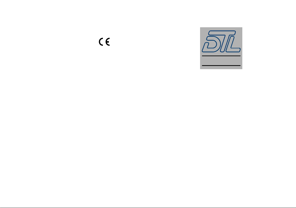
Functional block diagram
Installation and operation
The 4463A is simple to use and install.
•Set the dipswitches by referring to the table and description below
or the table on the rear of the unit.
•Connect video & audio inputs and SDI output.
•Apply power to the 4463A unit either via the locking power
connector from the external power supply or 1U rack frame, or by
sliding into the 2U rack mounting frame with central power
supplies.
•On power-up the 4463A will perform a short (3 second) self test.
The group LEDs will flash while this is in progress.
•The signal LED will be green when there is power and a valid SDI
output signal.
•One of the group LEDs will light corresponding to the group
selected by the switches. This LED will be green if the unit is
successfully embedding audio. The LED will be red otherwise.
•The switch settings can be altered whilst the unit is powered and the
changes are implemented immediately with the exception of
disabling the AGC.
•The 4-800MB mounting bracket can be used to install a MiniBlox
unit. The bracket should first be fixed vertically to any surface. The
MiniBlox can then be lowered onto the dovetail part of the bracket
with the front endplate uppermost to retain it.
Analogue Audio
Inputs
SDI
Output
CVBS
Input
AGC &
Clamping Dual 11-bit
Video ADC TBC &
De-jitter Embedded
Audio MUX Serialiser &
Cable Driver
24bit Audio
ADC
Micro-controllerControl Switches LEDs
- 5 -
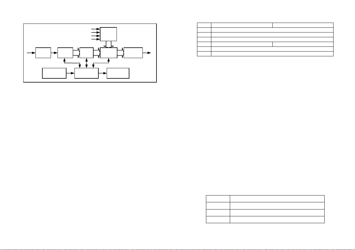
Switch settings
Switch OFF ON
1 Toggle group
2 Disable AGC
3 Disable de-jitter
4 24-bit 20-bit
5 Pedestal present
6 Toggle level (LED flashes red 1=18dB, 2=24dB & 3=custom)
Switch 1 sets the group into which audio packets are inserted. Moving the switch
to the on position then immediately to the off position selects the next available
group. The selected group is indicated by the LED on the end of the unit.
Switch 2 disables the automatic gain control. The AGC is capable of scaling an
input signal voltage of 0.5Vp-p to 2Vp-p to the nominal 1Vp-p level. This is useful
for restoring signals which have been subject to cable attenuation, or pre-
amplification. Disabling the AGC when the unit is in use has the effect of
freezing the gain to a constant value (worked out from the input signal at the
time). To completely remove the AGC, ensure that it is disabled before powering
the unit.
Switch 3 disables the jitter filter. The jitter filter can be disabled for locking to
extremely low quality or unstable analogue inputs.
Switch 4 controls the bit depth of the embedded audio. When the switch is off,
extended audio packets are multiplexed into the video signal (24 bit audio).
When the switch is on, extended audio packets are not included (20 bit audio).
Switch 5 defines if there is a 7.5 IRE pedestal on the input analogue video
source. When this switch is in the off position the unit does not expect a
pedestal, when in the on position the unit expects a 7.5 IRE pedestal to be
present on the input analogue video source.
Switch 6 controls the analogue level of the input; three levels are available
18dBu, 24dBu and a custom setting (default on delivery 20dBu). These levels
are toggled through by activating and immediately deactivating the switch. The
group LEDs will flash for two second as per the table below indicating the
operating analogue audio input level.
Level LEDs
18dB Group 1 flash red with group 2,3&4 green
24dB Group 2 flash red with group 1,3&4 green
Custom Group 3 flash red with group 1,2&4 green