XB110H Installation Guide
Page 2
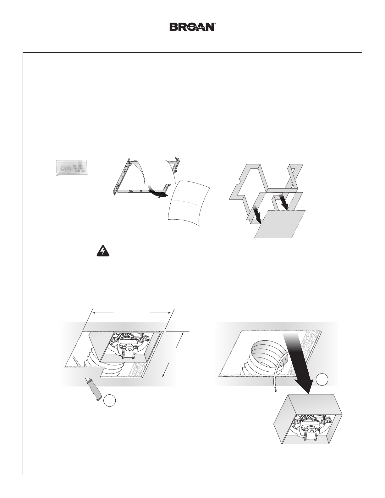
WARNING
TO REDUCE THE RISK OF FIRE, ELECTRIC SHOCK, OR
INJURY TO PERSONS, OBSERVE THE FOLLOWING:
1. Use this unit only in the manner intended by the manufacturer.
If you have questions, contact the manufacturer at the address
or telephone number listed in the warranty.
2. Before servicing or cleaning unit, switch power off at service
panel and lock the service disconnecting means to prevent
power from being switched on accidentally. When the service
disconnecting means cannot be locked, securely fasten a
prominent warning device, such as a tag, to the service panel.
3. Installation work and electrical wiring must be done by a
qualified person(s) in accordance with all applicable codes
and standards, including fire-rated construction codes and
standards.
4. Sufficient air is needed for proper combustion and exhausting
of gases through the flue (chimney) of fuel burning equipment
to prevent backdrafting. Follow the heating equipment
manufacturer’s guideline and safety standards such as those
published by the National Fire Protection Association (NFPA),
and the American Society for Heating, Refrigeration and
Air Conditioning Engineers (ASHRAE), and the local code
authorities.
5. When cutting or drilling into wall or ceiling, do not damage
electrical wiring and other hidden utilities.
6. Ducted fans must always be vented to the outdoors.
7. Use only ON/OFF switch, mechanical timer or relay-switched
control.
8. Acceptable for use over a tub or shower when connected to
a GFCI (Ground Fault Circuit Interrupter) - protected branch
circuit.
9. This unit must be grounded.
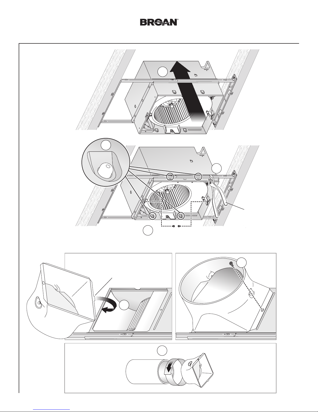
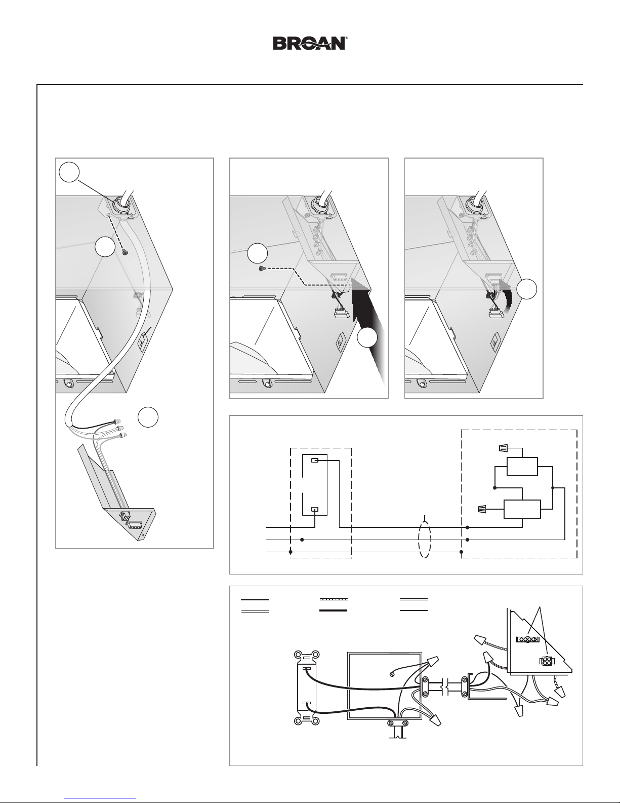
Typical Installation
CAUTION
1. For general ventilating use only. Do not use to exhaust
hazardous or explosive materials and vapors.
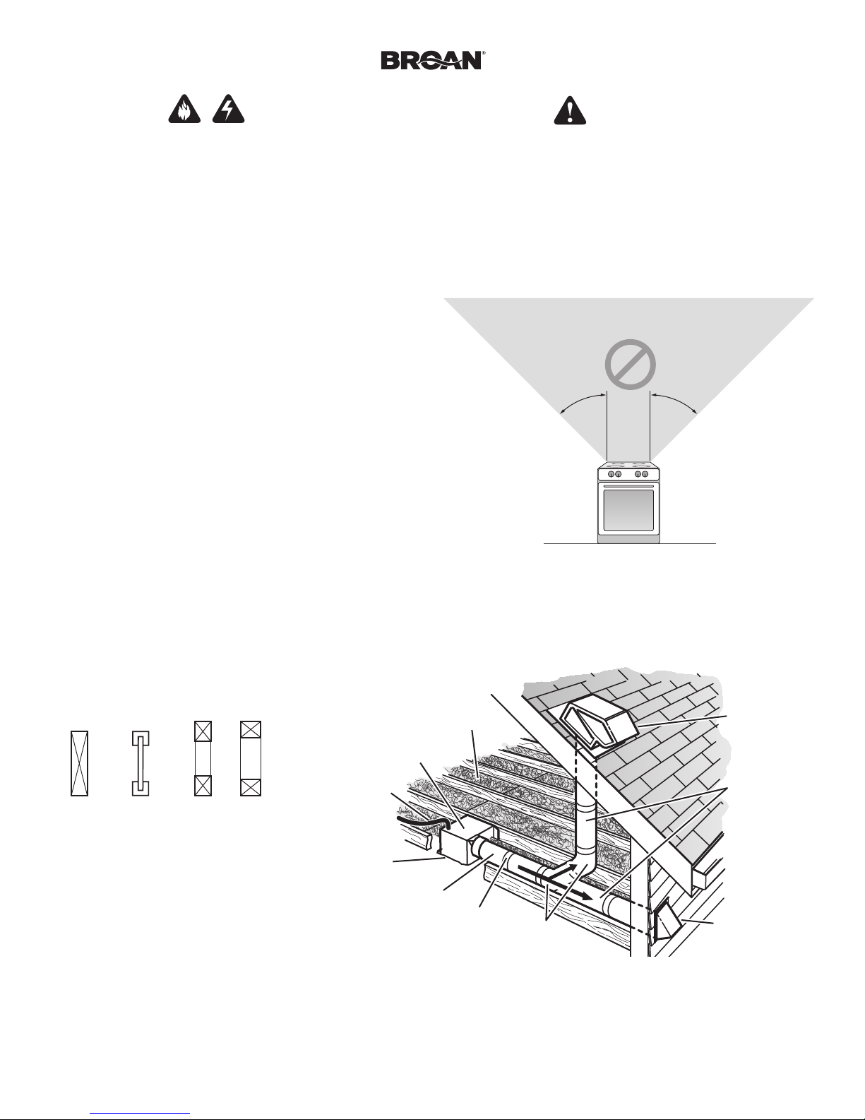
2. This product is designed for installation in flat ceilings. Sensor
will not function reliably if product is not installed in flat ceiling.
DO NOT MOUNT THIS PRODUCT IN A WALL.
3. To avoid motor bearing damage and noisy and/or unbalanced
impellers, keep drywall spray, construction dust, etc. off power
unit.
4. Please read specification label on product for further
information and requirements.
45° 45°
• Installation is the same for:
• Fits in 2" x 8" ceiling construction.
• Infinitely adjust the fan position
between joists from 14" to 24"
on center.
*Purchase
separately.
INSULATION*
(Place around and
over Fan Housing.)
ROOF CAP*
(with built-in
damper)
FAN
HOUSING
POWER
CABLE*
ROUND
DUCT*
ROUND
ELBOWS*
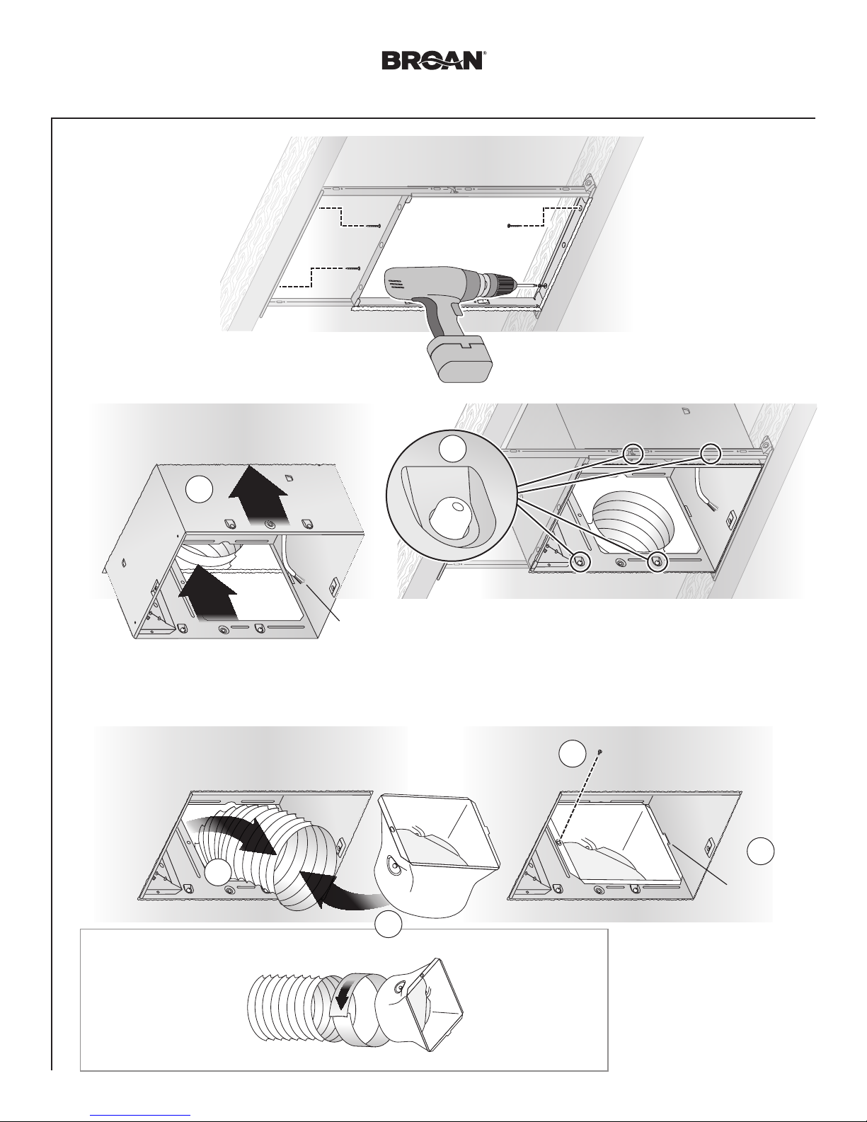
Seal gaps
around
Housing.
Seal duct
joints with
tape.
OR
Keep duct
runs short.
WALL CAP*
(with built-in
damper)
NOT FOR USE IN A COOKING AREA
Do not install above or inside this area
Floor
Cooking
Equipment
Joists I-Joists Trusses
The ducting from this fan to the outside of the building has a strong effect on the air flow, noise and en-
ergy use of the fan. Use the shortest, straighest duct routing possible for best performance, and avoid
installing the fan with smaller ducts than recommended. Insulation around the ducts can reduce en-
ergy loss and inhibit mold growth. Fans installed with existing ducts may not achieve their rated airflow.
6-inch round rigid metal duct is recommended for best performance.