Paul santos 570 DC User manual

Heat Recovery Unit
Paul Wärmerückgewinnung GmbH
August-Horch-Straße 7
08141 Reinsdorf
Germany
Tel.: +49 (0)375 - 303505 - 0
Fax: +49 (0)375 - 303505 - 55
Design version:
R – Right (supply air)
L – Left (supply air)
Status: 05.10
Operating Manual
Please keep this manual
with the unit!

IIEN
All rights reserved.
This operating manual has been produced with the greatest care and attention. Nevertheless, the publisher accepts no
liability for damage resulting from missing or incorrect information in this operating manual.

.....................................................................................................................................
1
1
1.2.1 General Information .......................................................................................................... 1
1.2.2 Warranty Terms ................................................................................................................. 1
1.2.3 Liability .............................................................................................................................. 1
2
1.3.1 Safety Regulations ........................................................................................................... 2
1.3.2 Safety Provisions and Safety Measures .......................................................................... 2
1.3.3 Symbols Used ................................................................................................................... 2
..........................................................................................................
...................................................................................................................... 3
2.1.1 Balanced Ventilation (controlled residential ventilation) ................................................. 3
2.1.2 Heat Recovery .................................................................................................................. 3
2.1.3 Bypass for Free Cooling ................................................................................................... 3
2.1.4 Frost Protection ................................................................................................................ 3
2.1.5 Fireplace Control .............................................................................................................. 3
2.1.6 0-10 V Input ....................................................................................................................... 3
2.1.7 Geothermal Heat Exchanger (optional) ........................................................................... 4
2.1.8 Frost Protection Device (optional) ................................................................................... 4
2.1.9 Enthalpy Exchanger (optional) ........................................................................................ 4
............................................................................................................
2.2.1 Display on Unit ................................................................................................................. 4
2.2.2 3-Position Switch ............................................................................................................. 5
2.2.3 Forced Ventilation with Bathroom Switch ....................................................................... 5
2.2.4 CO2 Sensor........................................................................................................................ 5
2.2.5 Touchscreen...................................................................................................................... 6
2.2.6 Membrane Keypad ........................................................................................................... 6
...................................................................................................................
2.4.1 Cleaning or Replacing Filters ........................................................................................... 8
2.4.2 Cleaning Valves (in the home) .......................................................................................... 9
..............................................................................................................................
2.5.1 Malfunction messages displayed on digital control panel .............................................. 10
2.5.2 What to do if a Malfunction Occurs? ............................................................................. 10
...................................................................................................................................

.........................................................................................................
.....................................................................................................................
...................................................................................................................
.............................................................................................................................
................................................................................................................
.......................................................................................................................
3.5.1 Transport and Unpacking ....................................................................................................... 15
3.5.2 Checking the Scope of Supply .............................................................................................. 15
........................................................................................................................
3.6.1 Wall mounting ......................................................................................................................... 15
3.6.2 Connecting the Air Ducts ....................................................................................................... 15
3.6.3 Connecting the Condensation Drain ..................................................................................... 16
..............................................................................................................
3.7.1 Display on Unit .......................................................................................................................17
3.7.2 P Menus for the Installer ........................................................................................................ 19
...............................................................................................................
.....................................................................................
3.9.1 Inspecting the Heat Exchanger and Fans ............................................................................. 23
3.9.2 Cleaning the Filters of Units Equipped with a Frost Protection Device ............................... 24
.....................................................................................................................................
3.10.1 Malfunction messages displayed on digital control panel ...................................................25
3.10.2 Overview of Malfunctions ....................................................................................................... 26
3.10.3 Malfunctions (or Problems) not Displayed ............................................................................ 30
.................................................................
...............................................................
..................................................................................
............................................................................................
...........................................................................................
..........................................................................................................................

EN
In addition to this general chapter, this operating
manual consists of:
• A section for the user
• A section for the installer.
Please read this operating manual carefully
before using the unit.
- User ¨ Chapters 1 and 2.
- Installer ¨ Chapters 1 and 3.
This operating manual contains all the information
required to safely and properly install, operate and
maintain the santos 570 DC. In addition, it should
serve you as a reference manual during service
work so that this can be carried out safely and re-
sponsibly. Due to ongoing further development of
the unit it is possible that your santos 570 DC may
differ slightly from the unit described in this manual.
This manual has been produced with the
greatestSFlb care and attention. However,
we do not accept legal liability for the con-
tents. Furthermore, the company reserves
the right to change the contents of this SFI-
boperating manual at any time without prior
SFlbnotication.
This chapter contains general information on the san-
tos 570 DC.
The unit carries the designation santos 570 DC,
hereafter referred to as santos.
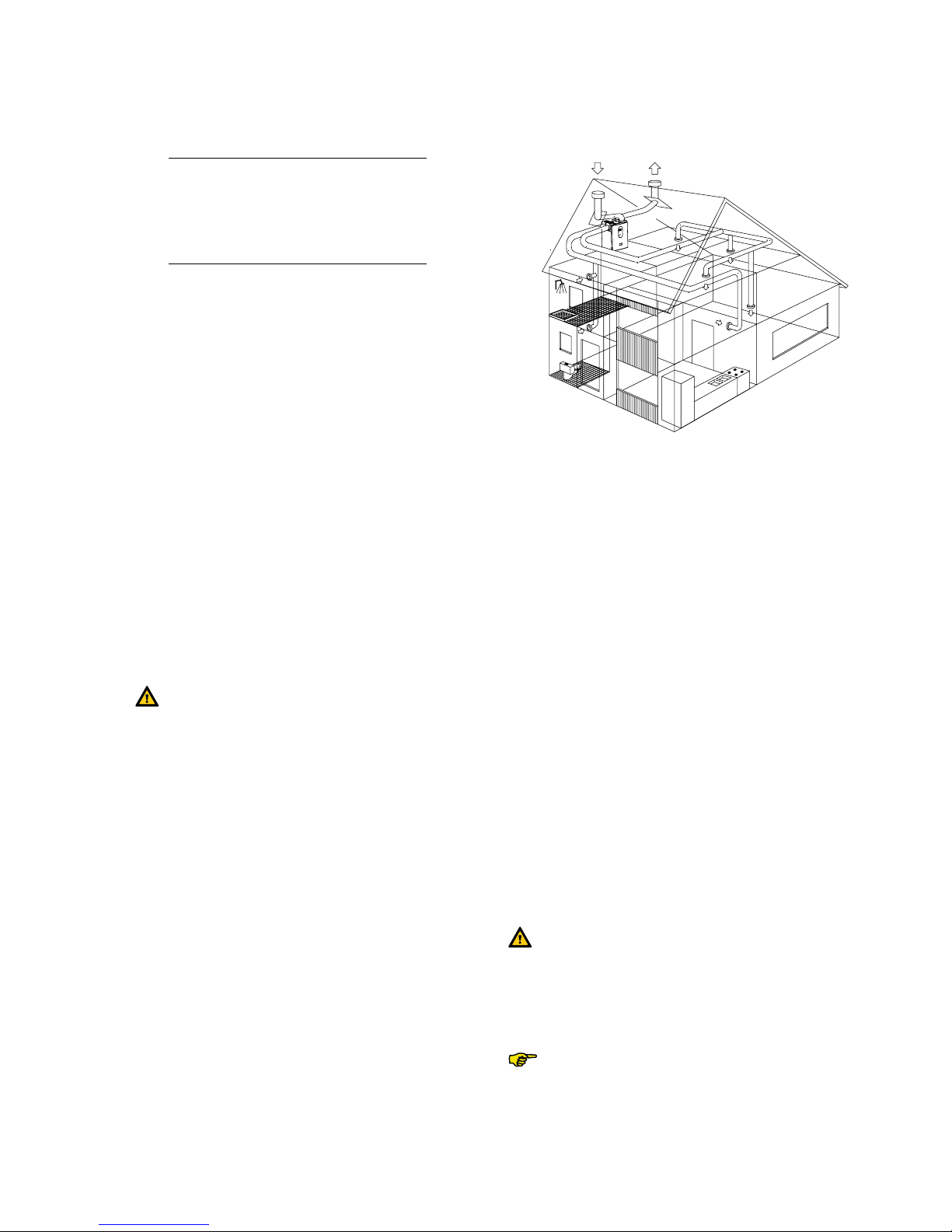
The santos is a balanced ventilation system with
heat recovery functionality that provides healthy,
balanced and energy-saving ventilation in residen-
tial premises. The santos identification plate is de-
picted below.
Our “General Terms and Conditions” in their latest
wording apply to the santos. The warranty period
begins when the unit is commissioned, but not later
than one month after delivery. The warranty extends
to material replacement, but does not include la-
bour costs. It shall only apply on proof of mainte-
nance having been performed by specialist installer
in accordance with our instructions.
The warranty period for our products shall be two
years commencing on the date of dispatch from our
work. Claims made under warranty shall only be ac-
cepted for material defects and/or manufacturing
defects that become apparent during the warranty
period. In the event a warranty claim is made the
santos must not be dismantled without the prior
written permission of the manufacturer. The manu-
facturer's warranty shall only apply to spare parts
that have been installed by a specialist installer.
The warranty will be voided if:
• The warranty period has expired;
• The unit is operated without an original PAUL
filter;
• Parts not supplied by the manufacturer are in-
stalled;
• The unit is used for any purpose other than the
intended use;
• Unauthorised changes or modifications have
been made to the system.
The santos has been developed and manufactured
for use in so-called "balanced ventilation systems".
Any other use is considered 'improper use' that
may result in damage to the santos or personal in-
jury for which the manufacturer accepts no liability
whatsoever.
The manufacturer accepts no liability for damage or
injury resulting from the following:
• Failure to observe the safety, operating and
maintenance instructions contained in this op-
erating manual;
• Spare parts not supplied or specified by the
manufacturer are installed.
Responsibility for the use of such spare parts
lies solely with the installer;
• Normal wear.
Voltage Hertz
Current
Power
Condenser
Phase
Articlecode
Type
Serial number
Protecion
class
Insolation
class

EN
Observe the safety regulations given in this operat-
ing manual at all times. Failure to observe the safety
regulations, warnings, comments and instructions
can result in personal injury or damage to the san-
tos.
• Unless clearly stated otherwise in this operat-
ing manual, the santos must be installed, con-
nected, commissioned and maintained by an
authorised installer only;
• The santos must be installed in compliance with
the general building, safety and installation reg-
ulations applicable at the place of installation as
issued by the respective local authority, water
and electricity utility company as well as other
official regulations and guidelines;
• Observe the safety regulations, warnings, com-
ments and instructions described in this operat-
ing manual at all times.
• Keep this operating manual close the santos
throughout its service life;
• Closely observe the instructions regarding the
regular replacement of filters and cleaning of
supply and exhaust air valves;
• Do not alter the specifications contained in this
document;
• Do not make any modifications to the santos;
• In order to ensure that the unit is inspected at
regular intervals, we recommend that the user
concludes a service contract. Your supplier can
provide you with the addresses of authorised
installers in your vicinity.
• The santos cannot be opened without using
tools.
• It must not be possible to touch the fans with
your hand. For that reason air ducts must be
connected to the santos. The minimum duct
length is 900 mm.
The following symbols are used in this operating
manual:
Caution!
Risk of:
- Damage to the unit;
- The operational performance of the unit
will be adversely affected if the instruc-
tions are not correctly observed.
Risk of physical injury to the user or the in-
staller.

EN
This chapter describes how you should use the santos.
Congratulations, you are now the own-
er of a santos 570 DC,
a heat recovery unit built by Paul
Wärmerückgewinnung GmbH.
We wish you the highest levels of com-
fort.
The santos unit offers the following functions:
• Balanced ventilation;
• Heat recovery;
• Bypass for free cooling:
• Frost protection;
• Fireplace control;
• Frost protection device (optional);
• 0-10 V input;
• Geothermal Heat Exchanger (optional);
• Enthalpy exchanger (optional).
These terms/properties are described briefly in
more detail in the following sections.
The santos unit has been designed to provide bal-
anced ventilation. Balanced ventilation systems
extract stale air contaminated with smells from the
kitchen, bathroom, WC(s) and, if necessary, a util-
ity room and introduce an equal volume of fresh air
to the living room, bedroom and children's room.
A gap below the doors guarantees good and bal-
anced air circulation in the home.
Ensure these gaps are not blocked by, for ex-
ample, rubber draught excluders or high-pile
carpets. This could prevent the system oper-
ating at an optimum.
Generally speaking, the balanced ventilation sys-
tem comprises the following elements:
• santos (A);
• Duct system for the intake of outside air (B)
and the extraction of indoor air (C);
• Air supply valves in the living rooms and bed-
rooms (D);
• Exhaust air valves in the kitchen, bathroom,
toilet and, if required, the utility room (E);
A
B
E
E
E
D
D
D
D
C
In addition to a well-balanced ratio between supply
and exhaust air volumes the santos unit also offers
the benefit of heat recovery. Heat recovery removes
the heat from stale exhaust air and transfers it to the
fresh, mostly cooler intake air.
The bypass is used most of all on warmer days in
the summer months to allow in the cool night air.
The bypass functions automatically. All that is re-
quired is to set a comfortable temperature level.
The santos is equipped with frost protection. Frost
protection is an automatic safeguard function that
drastically sinks (or even temporarily interrupts) the
intake of outside air into the santos when there is a
risk of frost. The risk of freezing exists in the winter
months with moderate to heavy frost.
A suitable safety device or integral system safe-
guard is required when jointly operating non room-
sealed fireplaces and ventilation systems if there is
a risk that a dangerous negative pressure can be
created in the room in which the fireplace is located.
The santos is equipped with fireplace control; how-
ever, this must be activated by the installer.
Fireplace control does not replace a safety
device designed to monitor the difference in
pressure; it is a technical precondition for
operating the unit when replaces are being
used at the same time.
Once the replace control is activated the
supply air and exhaust air fans cannot be
deactivated manually.

EN
The santos is equipped with four 0-10 V inputs. It
is possible to connect a variety of different controls
and sensors to these inputs. Several possible ex-
amples are listed below:
• CO2 sensor; ventilation control according to
carbon dioxide levels;
• Moisture sensor; ventilation control according
to moisture levels.
The ventilation system can optionally be equipped
with a geothermal heat exchanger. In addition, the
GHE control valve (Geothermal Heat Exchanger
control valve) makes it possible to route intake air
either directly to the santos or via the ground col-
lector. The geothermal heat exchanger provides
frost-free, temperature controlled intake air with
which the air is fed to the heat recovery unit. In
other words, during frosty weather the outside air
is heated with the aid of the underground geother-
mal heat exchanger before it enters the house via
the santos. By contrast during the summer months
when outdoor temperatures are high the intake air
can be cooled with the aid of the geothermal heat
exchanger before it is introduced into the house.
The GHE control valve operates automatically.
The geothermal heat exchanger is a part of
the ventilation system ductwork and is not
included with the santos.
An optional electric frost protection device can be
fitted in the santos. This has the advantage of en-
suring continued balanced ventilation. As a conse-
quence the supply of cold outside air need not be
restricted or can be restricted later if at all. The frost
protection device turns itself on and off automati-
cally.
The ventilation system can also optionally be
equipped with an enthalpy exchanger. An enthalpy
exchanger helps to regulate the humidity level in the
home. As well as recovering heat the enthalpy ex-
changer also recovers moisture. This process sees
moisture transferred from the exhaust air to the in-
take air and introduced into the ventilated rooms as
fresh supply air. Moreover, enthalpy exchangers are
less susceptible to frost.
In addition to the options described above it is also
possible to equip the santos as follows:
• Connection for forwarding malfunction mes-
sages (remote signalling, cabled);
• Connection for deactivating the fans (cabled);
• Connection for a device to signal a dirty exter-
nal filter.
It is possible to equip the santos with the following
operating aids:
• Display on unit;
• 3-position switch;
• Bathroom switch (optional) to temporarily set
the highest ventilation level;
• CO2 sensor;
• Touchscreen;
• Membrane keypad.
These operating aids are described briefly in more
detail in the following sections.
Settings can be set via the digital display and oper-
ating panel on the santos unit.
Call up menu Up
OK Down
Supply air off Extract air and
Supply air on
(LED green) (LED green)
Comfort temperature
Display read-out:
Ventilation level absent
Ventilation level low
Ventilation level medium
Ventilation level high
Menu display
Malfunction code (flashes)
Bypass
OK
MENU
·
·
·
OK
MENU
·
·
·
OK
MENU
·
·
·
OK
MENU
·
·
·
OK
MENU
·
·
·
1
A
2
3
X X
X X
•
1
A
2
3
X X
X X
•
1
A
2
3
X X
X X
•
1
A
2
3
X X
X X
•
1
A
2
3
X X
X X
•
1
A
2
3
X X
X X
•
1
A
2
3
X X
X X
•

5 ENInstructions for the User
1 MENU P2 Time delay values
2s P9 Status display
3sP1 Status display
Deactivation delay bathroom setting
1 P2 Time delay values
2 OK P21 Activation delay value
3sP22 Select 22
4 OK 30 Current setting
5▼(10 x or
hold down) 20 Select 20
6 OK P22 Current value is 20
7 MENU P2
8 MENU 1 Fan steps
Settings can only be made in the P2 menus.
The other P menus (P1 and P9) are read-only
menus.
• Press "MENU" (instead of "OK").
The display cannot be used to set santos
ventilation levels. The arrow keys are used
to select additional programmes.
A 3-position switch is used to set the ventilation
levels of the santos. One or more 3-position switch-
es can be installed in a home (for example, in the
kitchen).
When several position switches are installed
in the home the santos operates according
to the highest ventilation level set, unless a
different level is determined in the automatic
software control.
The 3-position switch enables you to set three ven-
tilation levels.
• Level 1 Low.
- Select this level for low ventilation
requirements.
• Level 2 Normal.
- Select this level for normal venti-
lation requirements.
• Level 3 High.
- Select this level when cooking,
showering and when high-level
ventilation is desired.
3
2
1
A bathroom switch can be used to temporarily set
the highest ventilation level available on the san-
tos. To allow excess moisture to be discharged as
quickly as possible after showering this switch is
generally installed in the bathroom. As bathroom
switches are available with very different designs,
no switch is illustrated here.
If desired, the user may enter activation and deac-
tivation time delays for the bathroom switch via the
digital control panel.
Activation delay ensures the highest ventilation level
available on the santos is not activated immediately,
but once the set activation delay time has elapsed.
If the bathroom switch is deactivated dur-
ing the set activation delay time the santos
maintains the current ventilation level and
the highest ventilation level is not activated.
Activation delay is not available to all types
of bathroom switches (such as a pulse
switch). In this case leave the activation de-
lay time setting at 0.
Deactivation delay ensures the santos does not re-
act immediately when the bathroom switch is deac-
tivated, but returns to the normal (or the originally
set) ventilation level once the set deactivation delay
time has elapsed.
The deactivation delay function remains
inactive if the bathroom switch is turned off
during the set activation time.
It is possible to integrate bathroom switch function-
ality into a light switch.
It is possible to regulate the santos with the aid of a
CO2 sensor. A CO2 sensor can be utilised either as a
3-position switch or to convert CO2 concentrations
in the indoor air to a 0-10 V signal to regulate the air
volume required to reduce the concentration CO2 to
permissible levels.

6EN Instructions for the User
The santos can be operated via a digital touch-
screen that you are able to order separately.
The touchscreen is mounted on the wall in the living
room from where it communicates with the santos.
The touchscreen is equipped with touch-sensitive
display providing straightforward access to the
functions.
The santos can also be operated via membrane
keypad that you are able to order separately. The
membrane keypad is mounted on the wall in the liv-
ing room from where you are able to communicate
with the santos.
The overview below contains a short description of the information you can view on the display of the membrane
keypad.
Various keys are available on the membrane keypad to allow you to operate and set the santos.
These keys are explained below.
Use this key to set the unit to operate at the highest ventilation level.
- to temporarily switch the highest level ON.
- to temporarily switch the highest level OFF.
Use this key to switch the supply air and/or exhaust air on or off.
- 1xSUPPLY AIR OFF (and EXHAUST AIR ON).
- 2xEXHAUST AIR OFF (and SUPPLY AIR ON).
- 3xSUPPLY AIR and EXHAUST AIR ON).
This key allows you to view or set the comfort temperature.
- for less than two secondsVIEW.
- for more than two secondsMAKE SETTINGS.
Use this key to set the following two functions.
- for less than two secondsSet ventilation programme. (AUTO/MANUAL).
- for longer than two secondsSet day and time.
Use this key to set a variety of functions:
- In the P menu→Set values.
- In the main screen→Determine ventilation level (A, 1, 2, 3).
Day and time
Current ventilation level
Automatic or manual
set ventilation
Message:
replace internal (I)
or external (E) filter
Mode of operation
• Supply and exhaust air
• Supply air mode only
• Exhaust air mode only
Geothermal heat recovery,
post-heater and/or
bypass on
Current comfort temperature

7 ENInstructions for the User
Menu P1 Status of function control settings
P11 Menu 21 currently active? Yes (1) / No (0)
P12 Menu 22 currently active? Yes (1) / No (0)
P13 Menu 23 currently active? Yes (1) / No (0)
P14 Menu 24 currently active? Yes (1) / No (0)
P15 Menu 25 currently active? Yes (1) / No (0)
P16 Menu 26 currently active? Yes (1) / No (0)
Menu P2 Setting time delays
P20 N/A (not used) 0 Min. 180 Min. 0 Min.
P21
(optional)
- Low voltage input
Activation delay for the bathroom
switch (to switch to the highest
level).
• The santos switches to the
highest
level
'n' minutes after the bath-
room switch is operated.
0 Min. 15 Min. 0 Min.
P22
(optional)
- Low voltage input
Deactivation delay for the bathroom
switch (to switch to the normal
level).
• the santos switches to the
normal
level
'n' minutes after the bath-
room switch is operated.
0 Min. 120 Min. 30 Min.
P23
(optional)
Deactivation delay for ventilation
level 3.
• If ventilation level 3 (the highest
level) is activated for a short pe-
riod (< 3 seconds) the santos will
maintain ventilation level 3 for the
time set in this menu.
If the position switch is operated
during the run-down time the santos
immediately switches to the set ven-
tilation level.
0 Min. 120 Min. 0 Min.
P24 Filter warning
• This option allows the user to
determine when the "
Filter dirty
"
warning message is displayed.
10
Weeks
26
Weeks
16
Weeks

8 System FunctionsEN
P25 N/A 1 Min. 20 Min. 10 Min.
P26 N/A 1 Min. 120 Min. 30 Min.
P27 Forced ventilation time.
• When " " is pressed for MORE
than two seconds the santos
switches to the highest ventilation
level for 'n' minutes before switch-
ing back automatically to the pre-
set level.
0 Min. 120 Min. 30 Min.
P29 N/A 1% 99% 10%
Menu P9 Status of function control settings (from menu P5 additional function
control settings)
P90 Fireplace control active? Yes (1) / No (0)
P91 Bypass open (=yes) / closed (=no)? Yes (1) / No (0)
P92 GHE control valve
Open (=yes) / closed (=no)
Yes (1) / No (0)
P93 N/A Yes (1) / No (0)
P94 0–10 V control active? Yes (1) / No (0)
P95 Frost protection active? Yes (1) / No (0)
P96 N/A Yes (1) / No (0)
P97 Enthalpy exchanger active? Yes (1) / No (0)
As the user you are obliged to service your san-
tos as follows:
• Clean or replace the filters;
• Clean the valves (in the home).
These maintenance procedures are described
briefly in more detail in the following sections.
Failure to (regularly) carry out mainte-
nance procedures on the santos will
impair the long-term performance of the
balanced ventilation system.
Clean or replace the filters as soon as the cor-
responding warning message is displayed on
the digital control panel.
Replace the lters (at least) once every
six months and clean the lters every
2-3 months.
"FiL" and "tEr" are indicated alternately on the
display.
• "
FILTER I
" -> The internal filters must be
cleaned or replaced.
• "
FILTER E
" -> The external filters must be
cleaned or replaced.
One of the filter warning messages stated
above will be indicated on the display of the
membrane keypad.
The internal lters are supplied as
standard with the santos. The (optional)
external lters belong to the ductwork of
the ventilation system and are not part
of the santos.

9System Functions EN
For replacement ...
1. Press OK (display on unit) or " " for at
least four seconds (key on keypad), until
the filter warning message is cleared.
2. Isolate the unit from the mains power sup-
ply.
3. Lift the front panel (A) upwards and re-
move from the santos unit.
4. Pull the handles (B) of the filter cartridges.
5. Pull the used filters (C) out of the santos.
6. Insert the new filters into the santos.
7. Ensure the handles (B) of the filter car-
tridges lock into place.
8. Reconnect the unit to the mains power
supply.
For cleaning ...
Instead of replacing the used filters (C) for new
ones you can clean the filters (when necessary)
using a vacuum cleaner.
Clean the lters (and valves) before us-
ing the santos for the rst time. The ven-
tilation system may have become soiled
with building dust during the building
phase.
The valves must be cleaned (at least) twice a
year.
1 Remove the valve from the wall or ceiling;
2 Clean the valve in a warm soap solution;
3 Rinse the valve thoroughly before drying
carefully;
4 Return the valve to EXACTLY THE SAME
POSITION (and IN THE SAME HOLE);
5 Repeat this procedure for the other valves.
About valve settings ...
The installer will have set the valves to ensure
the ventilation system operates to an opti-
mum. Therefore, it is imperative that you do
not change valve settings.
After cleaning, ALWAYS return all valves
in exactly the same position (and in the
same ventilation holes in the wall or ceil-
ing). Returning them to different posi-
tions could impair the performance of
the ventilation system.
The ventilation air is admitted and discharged
via valves. Gaps under the doors ensure that
the air is able to circulate in the home. To en-
sure that the right volumes of air are available
to the rooms, observe the following:
• block the gaps below the doors;
• alter the setting of the valves;
• swap the valves and their posi-
tions.
A malfunction to the santos is displayed as fol-
lows:
• A malfunction message is displayed on
the display of the unit;
• A malfunction message is displayed on
the display of the membrane keypad;
• A malfunction message is displayed on
the touchscreen;
The various malfunction messages are de-
scribed briefly in more detail in the following
sections.
If a malfunction occurs, a corresponding mal-
function message is displayed on the digital
control panel. An 'A' or 'E' code and a number
are always displayed on the display. Please re-
fer to the overview of malfunction messages
for the meaning of the corresponding code.

10 System FunctionsEN
In the event of a malfunction, please contact
the installer. Note the malfunction code indicat-
ed on the display of the digital control panel.
Please also note your santos model type. This
is indicated on the identification plate on the
top of your santos.
The santos must always remain connected to
the mains power supply unless it has to be shut
down for a compelling reason such as a seri-
ous malfunction, for the purpose of cleaning
or replacing the filters or for some other urgent
reason.
The house will not be mechanically venti-
lated if the unit is isolated from the power
supply. Moisture and mould can occur in
the dwelling as a result. Consequently,
you should avoid turning off the santos
for longer periods of time.
DIN 1946-6 species that apart from rea-
sons of maintenance and repairs ventila-
tion systems must be operated continu-
ally. When the home is unoccupied the
system should be operated at the lowest
ventilation level (level 1 set with 3-posi-
tion switch, level "Absent" or an intermit-
tent holiday programme set via the mem-
brane keypad on the operating unit).
It is possible that condensation will form
on the outside of the unit if the unit is in-
stalled in a room subject to above aver-
age levels of humidity (for example bath-
room or kitchen). This is perfectly normal
and does not impair the functional per-
formance of the system.
Discuss with your supplier what you should do
with your santos at the end of its service life.
If you are unable to return the santos to your
supplier, do not simply dispose of it via the
household waste; contact your local authority
to find out about the possibility of recycling the
components or environmentally safe process-
ing of the materials.

11System Functions EN
The standard version of the santos consists of the following components:
• Outer casing (A) made of coated sheet steel;
• Inner lining (B) made of high-quality expanded polypropylene (E)PP;
• Connections (C) for air ducts;
• 2 filters (D) for air filtration. Filter rating: Outside air G4, exhaust air G4;
• 2 energy-saving DC motors (E) with high-speed impeller;
• Highly efficient counter flow heat exchanger (F) or membrane moisture heat exchanger (optional);
• Switchbox (H1) for external connections and controller;
• Draw with control PCB (H2) with connections for the fans, bypass valve, frost protection device, temperature
sensors (T1-T4), 3-position switch with or without the (optional) malfunction and filter display and the (op-
tional) bathroom switch;
• Identification plate (I) with santos data (not visible);
• Condensation drain (J) for discharging condensation from the warm exhaust air.
· Sticker (K) indicating air connections (not visible).
• 230 VAC connection cable and plug with earthing contact (L);
• Display (M) to view data and make settings.
Observe the instructions contained in this chapter when installing the santos.

12 System FunctionsEN
Level Ventilation rate Value
Absent
50 m3/h at 7 Pa 13 W
Low
150 m3/h at 23 Pa 27 W
MediuM
250 m3/h at 77 Pa 68 W
HigH
450 m3/h at 323 Pa 313 W
MAxiMuM
550 m3/h at 240 Pa 365 W
Level Ventilation rate Value
Absent
50 m3/h at 7 Pa 0.11 A
Low
150 m3/h at 23 Pa 0.23 A
MediuM
250 m3/h at 77 Pa 0.55 A
HigH
450 m3/h at 323 Pa 2.21 A
MAxiMuM
550 m3/h at 240 Pa 2.56 A
Power supply
Supply voltage 230/50 V/Hz
Cos.phi 0,48 - 0,62
Noise level supply air fan
Level Ventilation rate Value
Absent
50 m3/h at 7 Pa 36 dB(A)
Low
150 m3/h at 23 Pa 50 dB(A)
MediuM
250 m3/h at 77 Pa 63 dB(A)
HigH
450 m3/h at 323 Pa 78 dB(A)
MAxiMuM
550 m3/h at 240 Pa 79 dB(A)
Noise level exhaust air fan
Level Ventilation rate Value
Absent
50 m3/h at 7 Pa 29 dB(A)
Low
150 m3/h at 23 Pa 39 dB(A)
MediuM
250 m3/h at 77 Pa 49 dB(A)
HigH
450 m3/h at 323 Pa 63 dB(A)
MAxiMuM
550 m3/h at 240 Pa 64 dB(A)
General specifications
Material of counter flow heat exchanger Plastic
Material of enthalpy exchanger Cellulose
Material of inner lining (E)PP / PA / PA
Heat recovery up to 95%
Weight 47 kg

13System Functions EN

14 System FunctionsEN
Observe the following points when assessing if the
santos can be installed in a particular room:
• In addition to observing the instructions con-
tained in this manual you must comply with lo-
cal safety and installation regulations specified
by, amongst others, public utility companies
when installing the santos.
• When selecting the place of installation ensure
there is sufficient space around the santos for
air connections, supply and exhaust air ducts
as well as for carrying out maintenance work.
• The following installations must be available in
the room:
- Air duct connections.
- 230 V mains power supply.
- Connection for the condensation drain.
• Install the santos in a frost-protected room.
Ensure the condensation water is discharged
frost-free with a downward gradient and in-
cludes a trap.
We recommend you do not install the unit in
a room with an on average higher level of hu-
midity.
To ensure good and draught-free ventilation
of the dwelling, ensure there are 10 mm gaps
below the indoor doors. If these gaps are
blocked, for example with door seals or high-
pile carpets, the circulation of air inside the
dwelling will stagnate. This would prevent
the system from operating at an optimum.
Proceed with due care and attention when trans-
porting and unpacking the santos.
Remove the unit from the packaging only
immediately prior to mounting the unit.
To protect against the ingress of building
dust and moisture cover open ends (duct
connections) during any interruptions to in-
stallation procedures.
Please contact your supplier immediately if you dis-
cover any damage to or parts missing from the de-
livered product. The scope of supply includes:
• Santos 570 DC;
Check the identification plate to ensure it is the
correct unit type.
• Mounting brackets;
• Operating Manual
the santos on a wall with a mass of at least
200 kg/m2.
With other walls we recommend the use of a mount-
ing frame to install on the floor (optional). This helps
to avoid the transmission of structure-borne noise
as much as possible.
• the supplied mounting bracket to the
wall horizontally.
• the condensation drain (not included
in the scope of supply) to the underside of the
santos. The given dimension of 235 mm is in-
tended as a guideline. This value depends on
the type of trap selected.
• Ensure that at least 1 metre of space is left in
front of the santos to allow future maintenance
work.
Observe the following specifications when fitting air
ducts:
• Install silencers of at least 1 meter in length to
the supply and exhaust air connections of the
unit. For relevant advice, please contact Paul
Wärmerückgewinnung GmbH.
• Fit the air ducts to be connected (minimum
ø180 mm), ensuring they are sealed airtight and
offer as little resistance to the flow of air as pos-
sible.
• To guarantee the basic functionality of the bal-
anced ventilation system when utilising flexible
ducting, use only air ducting material from Paul
Wärmerückgewinnung GmbH.
•
. This
prevents the formation of condensation on the
outside of the ducts.
• If it is not possible to avoid creating a low point
when installing the discharge air ducting from
the discharge air connections on the unit to the
wall opening, then a further condensate drain-
age line must be connected at the low point; the

15System Functions EN
reason being discharged air is saturated with
water vapour when confronted with cold out-
door temperatures that causes droplets to form
on the inside of the ductwork.
• If it is planned to install a silencer at the dis-
charge air connection, then this must be routed
upwards by a bend to protect it against being
soaked by condensation flowing back out of
the discharge air ductwork. When mounting the
unit ensure the condensate can be drained with
a good downward gradient along a longer dis-
tance.
• When routed across a roof the exhaust air duct
must have a double-walled or insulated roof
opening. This prevents the formation of con-
densation between the layers of the roof.
• To prevent unnecessary temperature losses in
both summer and winter we recommend you in-
sulate the supply and exhaust air ductwork with
thermal, vapour-tight insulation.
Extract air
Exhaust air
Supply air
Intake air
santos - left
Intake air
Supply air
Exhaust airExtract air
santos - right
santos 570 DC - RIGHT
santos 570 DC - LEFT
The warm extract air is cooled by the intake air in
the heat exchanger. As a result, moisture contained
in the inside air condenses in the heat exchanger.
The condensation water that forms in the heat ex-
changer is directed towards the trap.
The connection for the condensation drain has an
outside diameter of 32 mm. This is located on the
underside of the santos.
• the condensation drain with a pipe or
hose to the water seal of the domestic waste-
water system.
• the upper edge of the water seal at
least 40 mm below the condensation drain of
the santos unit.
• that the end of the pipe or hose ends be-
low the water level.

16 System FunctionsEN
Ensure that the water seal connected to the
domestic wastewater system is always lled
with water.
Ensure that the hose end terminates at least
60 mm below the water level. This will pre-
vent the santos from drawing in air.
Do not connect the condensate drain direct-
ly to the sewage drain system (for example
owing freely into funnel with condensation
drain at the sewage system)
The santos can be put into operation after instal-
lation.
It is possible to carry out the commissioning proce-
dures utilising P menus on the digital control panel.
These P menus allow various settings (in particular
for ventilation control) to be selected for the san-
tos. An overview of the available P menus is given
below:
P1 View status (from menu P2)
P2 Set time delay values
P3 Set ventilation levels
P4 View temperatures
P5 Set additional control functions
P6 Set additional control functions
P7 Read and reset malfunctions (and sys-
tem information)
P8 Set 0-10 V inputs
P9 View status (from menu P5)
The P menus P1, P2 and P9 are user accessible
and serve mainly for viewing statuses and setting
time delays. The remaining P menus P3 to P8 are
reserved for the installer.
The bypass valve will not move in the rst
4 minutes following a drop in voltage, if the
setting mode is not activated.
Call up menu Up
OK Down
Supply air off Exhaust air and
supply air on
(LED green) (LED green)
Comfort temperature
Display read-out:
Ventilation level absent
Ventilation level low
Ventilation level medium
Ventilation level high
Menu display
Malfunction code (flashes)
Bypass
1 MENU P2 Time delay values
2s + ▼
(3 seconds)
P3 Press keys
simultaneously
3sP4 Temperatures
4sP5 Control settings
5sP6 Control settings
6sP7 Malfunction / reset /
Self-test
7sP8 0 - 10 V inputs
8sP9 Status display
Set the power of the supply air fan at
THE MEDIUM LEVEL to 40%
1 MENU P2 Time delay values
2s + ▼
(3 seconds) P3 Press keys
simultaneously
3 OK P30 Exhaust air fan
Level A
4s (6x) P36 Select P36
5 OK 50 Current setting
6▼(10 x or
hold down) 40 Select 40
7 OK P35 Current value is 40
8 MENU P3
9 MENU 1 Fan steps
Some P menus (for example P1 and P9) are
view only.
• Press "MENU" (instead of "OK").
The display cannot be used to set the san-
tos ventilation levels. Arrow keys are used
only to determine additional programmes.
1
A
2
3
X X
X X
•
1
A
2
3
X X
X X
•
1
A
2
3
X X
X X
•
1
A
2
3
X X
X X
•
1
A
2
3
X X
X X
•
OK
MENU
·
·
·
OK
MENU
·
·
·
OK
MENU
·
·
·
OK
MENU
·
·
·
OK
MENU
·
·
·
1
A
2
3
X X
X X
•
1
A
2
3
X X
X X
•
This manual suits for next models
1
Table of contents
Popular Ventilation manuals by other brands

Delta
Delta SIG80 Installation and operating instructions

Vallox
Vallox Vallox TSK Multi 80 MV manual

DuraVent
DuraVent DCL manual

Zehnder Rittling
Zehnder Rittling ComfoAir 550 Luxe Installer manual

DVS
DVS Positive Pressure Home Ventilation System operating guide

Airflow
Airflow Duplexvent Flexi DV1100 Installation, use and maintenance manual