OPERATING AND INSTALLATION INSTRUCTIONS SYSTEM VENTECH LG 150 PAGE 6
SPECIALIST PERSONNEL GENERAL
USER
STIPULATIONS FOR OPERATION WITH
FIREPLACES
Due to heavy load and irregular operation,
extract air from any kitchen extractor
hoods that may be present must not
be integrated into the dwelling's air-
conditioning system.
Extract air from such extractor hoods
must be conducted separately to the
outdoors by means of an exhaust air pipe.
Exhaust air extractor hoods must be
operated via separate air pipes with
suitable air replenishment e.g. by
means of window ventilation or in air
recirculation mode.
If an extractor hood is operated without
separate introduction of supply air,
air volume in the dwelling becomes
unbalanced. Proper functioning of the
domestic air-conditioning system cannot
be guaranteed in such instances (odour
carryover etc.)
Another option is to operate the extractor
hood in recirculation mode.
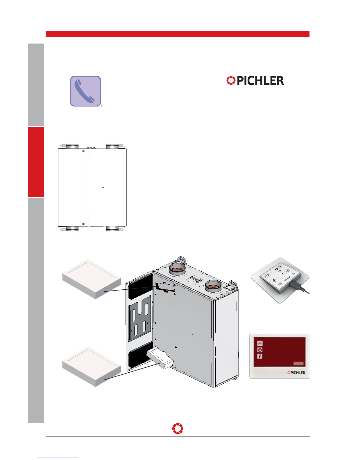
The LG 150 System VENTECH compact
ventilation unit range has been developed
and manufactured for controlled mechan-
ical ventilation and deaeration of spaces
with purposes similar, for example, to
seminar rooms and small oces.
For proper operation of the central air
conditioning systems, it must be possible
to close any ducts for combustion air and
flue gas systems of fireplaces drawing in
room air.
Any other use shall be deemed improper
use and may result in personal injury or
damage to the LG 150 System VENTECH
compact ventilation unit range, for which
the manufacturer cannot be held liable.
The manufacturer accepts no responsibility
for any damages due to:
• Failure to observe the safety, operating
and maintenance instructions provided
in this operating and installation manual.
• Installation of spare parts that have
not been supplied by the manufacturer,
whereby the responsibility for use of
such spare parts lies wholly with the
system's constructor/installer.
• Normal wear and tear.
LIABILITY
STIPULATIONS FOR OPERATION WITH
EXTRACTOR HOODS
Changes reserved
Local requirements in terms of standards,
laws and directives, must be taken into
account .
The central air conditioners with heat
recovery should not be installed in
comparably sized rooms, apartments
or facilities with room air dependent
heating apparatus unless:
• safety systems are in place to prevent
simultaneous operation of room air
dependent heating apparatus and units
extracting air, or
• special safety systems will monitor
waste gas extraction of a heating
apparatus dependent on room air.
Heating apparatus running on liquid or
gaseous fuels and drawing in room air,
or air conditioning systems, must switch
o should a safety system trigger. The
air conditioning system must switch o
should the safety system trigger in case
of solid fuel heating apparatus drawing
in room air.
Central air conditioning equipment for
controlled ventilation and extraction of air
in an apartment or similar facility shall
not be installed if the facility has room air
dependent heating apparatus connected
to waste gas units with multiple infeeds.
For normal operation of central air
conditioning systems, it must be possible
to close any ducts for combustion air
or waste gas systems from heating
apparatus dependent on room air. Shut-
o systems for waste gas from solid
fuel heating apparatus must be manual.
The position of the operating lever must
indicate the status of the shut-o device.
This is deemed complied with if a shut-o
system is used to block soot (soot shut-
o).
Fire protection requirements
The regional regulatory provisions,
especially the fire protection regulations
for air conditioning of buildings,
as amended, must be taken into
consideration when installing the air
conditioning system in accordance with
the instructions for fire protection.