Bromic Heating DC100NG-S Manual

1 | Page Rev4.1
INSTALLATION & OPERATING INSTRUCTIONS
WOK BURNER with FLAME SAFEGUARD
FOR INSTALLATION AND USE INDOORS ONLY
- NOT FOR PORTABLE USE -
AGA APPROVAL NO.: 7092 G
Models for use with Natural Gas:
DC100NG-S Single Burner Wok Cooker
DC200NG-S Double Burner Wok Cooker
Models for use with Universal LP Gas:
DC100-S Single Burner Wok Cooker
DC200-S Double Burner Wok Cooker
FEATURES
Electronic ignition system incorporating piezo-electric elements.
Wok burner suitable for all types of cooking from simmering to stir-frying.
High-energy, high-efficiency burner reduces gas consumption.
Removable control knob incorporating burner ignition.
Large trivet for greater cooking flexibility.
Easy to clean stainless steel top and control panel.
IMPORTANT
Read these instructions carefully before use. Familiarize yourself with the appliance before connecting it to its gas
supply. Keep these instructions for future reference.
THE APPLIANCE MUST BE INSTALLED IN COMPLIANCE WITH THE FOLLOWING:
AS/NZS 5601.1 – Australian Standard for Gas Installations;
Manufacturer’s installation instructions
Local gas fitting regulations
Municipal building codes and
Any other relevant statutory regulation(s). Refer to AS/NZS 5601.1 for piping size details.
GAS PRESSURE REGULATOR DETAILS
FOR NG MODELS
The NG model they must be installed in accordance with AS/NZS 5601.1 by an authorised gas fitter / plumber.
A natural gas regulator Maxitrol RV20LM, AGA Approval No. 3088 with an outlet pressure of 1.0kPa is included with this
appliance.
FOR LP MODELS
Where the LPG models are connected to a permanently fixed reticulated LP Gas supply, they must be installed in
accordance with AS/NZS 5601.1 by an authorised gas fitter / plumber.
Where the LPG models are used in quasi-outdoor/indoor areas such as an alfresco or balcony situation the purchaser
(consumer) may use an approved LP Gas regulator and hose assembly connected to a 4.5 or 9.0kg LP Gas cylinder.
The use of 4.5 or 9.0kg LP Gas cylinders inside a building should be avoided.
The appliance must be connected to a certified hose and regulator assembly to ensure safe operation as follows: LP regulator
fitted with a POL type inlet fitting, outlet pressure of 2.75kPa and Certified to AS4621 and an 8mm nominal bore hose
(maximum length 1.5 metres) certified to AS/NZS 1869. Avoid twisting or kinking thee flexible hose.
Inspect the hose regularly. Recommended that the hose be replaced every 5 years.
WARNING: THE CORRECT ASSEMBLY MUST BE USED - DO NOT USE ADAPTORS – If a replacement is required contact Bromic Pty
Ltd.

2 | Page Rev4.1
SAFETY WARNINGS
This appliance must only be used INDOORS and in a well ventilated area only.
DO NOT USE IN CARAVANS, TENTS, MARINE CRAFT, CARS, MOBILE HOMES.
Failure to follow instructions in this manual could result in physical injury and/or property
damage.
Hazardous fire or explosion may result if instructions are ignored.
Leak-test all connections before use.
Never check for leaks with a match or open flame
DO NOT use this appliance in freezing conditions.
Do not store or use petroleum products or other flammable vapours and liquids in the vicinity of
this appliance
Do not use or store flammable materials in the appliance or near this appliance.
Carbon monoxide hazard – this appliance can produce carbon monoxide which has no odour.
Using the appliance in an enclosed space may cause death.
Do not use this appliance as a space heater under any circumstances.
This appliance is suitable for use with the specified gas type only. The appliance is only to be
connected to the gas type specified on the data plate located on the RH side panel of the
appliance.
Do not modify this appliance or changed in any way.
Do not use this appliance where petroleum products or other liquids having flammable vapours
are stored or used.
Children and adults should be alerted to the high temperatures of the appliance and its effect
on surrounding surfaces, clothing and skin
Children or the elderly should be supervised when near this appliance
Do not hang clothing or other flammable material on or near this appliance
Always keep flammable materials away from the appliance.
Make sure that you use cooking woks, pots or pans that sit firmly on the trivet. Do not use pots
that are too small / large for the burner size, as they could be unstable on the trivet.
If abnormal combustion is observed when in use, turn off the gas valve and examine the
cooker (refer to trouble-shooting guide)
A SPIDER’S WEB CAN INTERFERE WITH THE FLOW OF GAS / AIR INTO THE BURNER, THE
OPENING INTO THE BURNER DIRECTLY IN FRONT OF THE GAS VALVE SHOULD BE CHECKED
REGULARLY AND CLEARED WITH A PIPE CLEANER OR SIMILAR LENGTH DEVICE. (SEE
MAINTENANCE)
FOR YOUR SAFETY – WHAT TO DO IF YOU SMELL GAS
The strong and distinctive odour of gas may make you aware of a gas leak. If you suspect a gas
leak:
Extinguish all naked flames
Immediately turn off all appliances and pilot lights.
Do not allow gas to build up in the area. Open all doors and windows to both disperse the gas
and provide ventilation of fresh air.
Allow sufficient time for any accumulated gas to disperse
Ensure all persons are evacuated
Turn off the gas supply at the source (gas meter, gas bottle etc.) and contact an authorised gas
fitter immediately.
The appliance must only be serviced and repaired by an authorised person such as a licensed
plumber or gas fitter.
NEVER ATTEMPT TO REPAIR THE APPLIANCE YOURSELF

3 | Page Rev4.1
INSTALLATION – NOTES TO THE INSTALLER
The LPG models & Natural models connected to a permanently fixed reticulated LP Gas supply, must be installed in
accordance with AS/NZS 5601.1 by an authorised gas fitter / plumber
Where the LPG models are used in quasi-outdoor/indoor areas such as an alfresco or balcony situation the purchaser
(consumer) may use an approved LP Gas regulator and hose assembly connected to a 4.5 or 9.0kg LP Gas cylinder.
The use of 4.5 or 9.0kg LP Gas cylinders inside a building should be avoided
INSTALLATION
Position of Wok Cooker outlet pipe at the rear of the unit:
DC100-S Series DC200-S Series
SAFETY PRECAUTIONS
MAKE SURE YOU AND YOUR LICENSED GAS FITTER/PLUMBER CAREFULLY READ ALL OF THESE
INSTRUCTIONS BEFORE INSTALLING THE APPLIANCE. FOLLOW ALL WARNINGS AND
INSTRUCTIONS MARKED ON THE APPLIANCE.
Do not install a damaged appliance. Contact Bromic if the appliance is damaged.
Check the gas type of the appliance and make sure it is suited for the type of gas supplied. The data plate is
located on the RH side panel of the appliance. Adhere the duplicate data plate to an accessible location near the
appliance i.e. rear of a cupboard door.
Make sure the gas inlet pipe is clean and not blocked before connecting the gas.
Selecting a suitable position for the appliance is important to ensure maximum performance, economy and safety of
operation.
Always ensure that adequate fresh air is provided for ventilation. The minimum volume of the room where appliance
is installed: 1.5 M2 per MJ. Refer to AS/NZS 5601.1 for details of the necessary ventilation requirements including
the size of the openings.
The appliance must only be operated on a level, firm non-combustible surface.
This appliance shall not be installed in a position where it could create a fire hazard and the minimum clearances to
combustible materials must be observed, as described below.
CLEARANCES
This appliance must be installed so that a vertical clearance of at least 600mm is maintained between its burners
and any combustible material. Where it is not practical, the underside of any combustible material with a vertical
clearance of less than 600mm above a burner should be protected by mill-board at least 6mm thick which is
covered with sheet metal not less than 0.4mm thick, or protected by an equivalent material extending at least
225mm beyond the sides of the cooker. In either case, the vertical clearance above the cooker burner should not
be less than 450mm.
The minimum clearance from the appliance to rear or sides of combustible surfaces must be no less than 225mm.
When the appliance is installed abutting a side or rear wall, the wall must be of non-combustible material, e.g. brick.
If surrounding walls are constructed with a combustible material, contact your local Gas Authority for information on
clearances required.
Combustible material Range hood

4 | Page Rev4.1
1. Remove all the packing materials from the appliance before connecting the gas.
2. Appliance Gas inlet fitting located at the rear of the appliance: ¼ ” BSPM for Natural Gas and for LP Gas, 5/8-18
UNF thread (known as 3/8 SAE male fitting).
3. Ensure that the gas supply connection point is accessible when the appliance is installed.
4. For Natural Gas (NG) Models:
The appliance is supplied with an approved regulator & must be installed in accordance with AS/NZS 5601.1 by
an authorised gas fitter / plumber. The connecting hose must be an approved type. The connection of hose to
the gas supply must provide a secure connection free of gas leakage. The hose should not be subjected to
abrasion, kinking or permanent deformation and should be able to be inspected along its entire length with the
appliance in the installed position. For gas supply pressure see technical specification on page10
Fix the appliance onto the bench by drilling holes into the bench top to the position of the fixing brackets. Place
brackets into position on the appliance over the burner support beam and screw into position using the supplied
screws. Screw the brackets securely to the bench top using the appropriate nut and screws
Check for gas leakage at all joints with soapy water or other approved methods
For LP Gas Models:
Where the LPG models are connected to a permanently fixed reticulated LP Gas supply, they must be installed
in accordance with AS/NZS 5601.1 by an authorised gas fitter / plumber.
Where the LPG models are used in quasi-outdoor/indoor areas such as an alfresco or balcony situation the
purchaser (consumer) may use an approved (certified) LP Gas regulator and hose assembly connected to a 4.5
or 9.0kg LP Gas cylinder.
Note: a certified hose LPG gas regulator and hose assembly is one that where LP regulator fitted with a POL
type inlet fitting, outlet pressure of 2.75kPa and Certified to AS4621 and an 8mm nominal bore hose (maximum
length 1.5 metres) certified to AS/NZS 1869
The use of 4.5 or 9.0kg LP Gas cylinders inside a building should be avoided.
Fix the appliance onto the bench by drilling holes into the bench top to the position of the fixing brackets. Place
brackets into position on the appliance over the burner support beam and screw into position using the supplied
screws. Screw the brackets securely to the bench top using the appropriate nut and screws
Check for gas leakage at all joints with soapy water or other approved methods
.
UNDER NO CIRCUMSTANCES SHOULD A NAKED FLAME BE USED IN CHECKING
FOR GAS LEAKS.
PRESSURE ADJUSTMENT OF THE REGULATORS
Never adjust the pressure of the regulators. The natural gas regulator is already adjusted to the correct pressure of
1.0kPa.
If you suspect the pressure of the regulator is abnormal, please contact Bromic Pty Ltd for assistance.

5 | Page Rev4.1
CORRECT ASSEMBLY OF BURNER HEAD
TO GAS FITTERS - BEFORE LEAVING AFTER INSTALLATION
1. Make sure all connections are gas tight and have no gas leakage.
2. Check that the aeration control is adjusted to the right position to enable the burner to achieve
a blue and vigorous flame to reach complete combustion. The Primary air shutter is in fully
open position.
3. Make sure the flame is normal when adjusted to low flame; there should be no yellow flames at
anytime.
4. Check there is no backfire when the appliances is turned down to low or turned off.
5. The main gas supply valve is off
6. The gas control on the appliance is off
7. The consumer fully understands the safety precautions, operation and maintenance
8. The operation of the ignition system is satisfactory.
9. The operation of the flame (thermocouple) safeguard is satisfactory.
10. Flame abnormalities. If any of the following are observed during operation of the appliance:
Carbon build up on the appliance or pans, Excessive yellow tipping of the burner flame, flames
lifting off the burner ports or flashing back. Flame abnormality may be due to gas supply
restriction or blockage of burner ports or venturi. Gas spillage may occur if the burner inlet is
partially blocked by spider webs the gas may ignite around the burner inlet. You should cease
using the appliance. If a normal flame cannot be achieved contact Bromic Pty Ltd or an
authorized agent for assistance.
DO NOT ATTEMPT REPAIRS YOURSELF.

6 | Page Rev4.1
APPLIANCE DIMENSIONS
COMPONENTS AND PARTS
DC100NG-S & DC100-S DC200NG-S & DC200-S
PARTS INDEX
1. Body 3. Outer Ring Brass Cap 5. Tray 7. Rubber Leg
2. Trivet 4. Inner Ring Brass Cap 6. Burner Head 8. Knob
9. Thermocouple
OPERATING INSTRUCTIONS
USING THE APPLIANCE
Follow these steps when operating the appliance:
LIGHTING THE APPLAINCE
1. Make sure the ignition knob set to the ‘OFF’ position.
2. Push in and turn the ignition knob anti-clockwise until a “click”
sound is heard. Keep the control knob depressed for 5 seconds
allow the flame (thermocouple) safeguard to operate.
Release the control knob.
Turn the control knob to the required setting.
If the burner does not come on, turn the control knob to the off setting and repeat the steps
above. This time, press and hold the control knob for longer (up to 10 seconds).
Warning – Risk of deflagration!
3. If after 10 seconds the flame does not ignite, switch off the burner and open a nearby window
or door. Wait at least one minute before trying to switch the burner back again. If the flame still
does not ignite contact Bromic Pty Ltd or an authorized agent for assistance.
4. Flame abnormalities. If any of the following are observed during operation of the appliance:
Carbon build up on the appliance or pans, Excessive yellow tipping of the burner flame, flames
lifting off the burner ports or flashing back. Flame abnormality may be due to gas supply
restriction or blockage of burner ports or venturi. Gas spillage may occur if the burner inlet is
partially blocked by spider webs the gas may ignite around the burner inlet. You should cease
using the appliance and contact Bromic Pty Ltd or an authorized agent for assistance.
Lighting the cooker
ON
OFF
9 4 3

7 | Page Rev4.1
ADJUSTING THE FLAME
1. Turn the ignition knob to the required flame setting position as shown below.
TURNING OFF THE COOKER
1. Turn the ignition knob fully back to the OFF position
A few seconds after the burner is switched off, a sound
(thud) will be produced. This is not a fault - this means
that the safety device is no longer operating.
When using certain pots or pans, a slight and
temporary deformation of the stainless-steel cooking surface
may occur. This is normal and does not affect the
functionality of the appliance.
The following advice is intended to help you save energy and prevent pan damage. Use pans
which are the right size for each burner. Do not use small pans on the burners. The flame must not
extend beyond the sides of the pan. Do not use damaged pans, which do not sit evenly on
the hob.
Pans may tip over. Only use pans with a thick base
Always centre the pan over the burner, not to one side. Otherwise it could tip over.
Place the pans on the pan supports, never directly on the burner.
Make sure that the pan supports and burner caps are correctly positioned before using the
appliance Pans should be placed on the hob carefully.
Do not strike the hob and do not place excessive weight on it.
CAUTION - CORRECT PLACEMENT OF UTENSILS
DO NOT SPRAY AEROSOLS IN THE VICINITY OF THIS APPLIANCE WHILE IT IS IN
OPERATION.
DO NOT USE OR STORE FLAMMABLE MATERIALS IN OR NEAR THIS APPLIANCE.
Turning off the cooker
ON
OFF
Do not place
anything e.g.
Flame tamer,
asbestos mat
etc. Between pan
and pan support
as serious
damage to the
appliance may
result.
Do not remove
the pan support
and enclose the
burner with a
wok stand as this
will concentrate
and deflect heat
onto the hotplate.
Do not use large
pots or heavy
weights which
can bend the pan
support or deflect
flame onto the
hotplate.
Locate pan
centrally over the
burner so that it
is stable and
does not
overhang the
appliance.
Use only wok
support supplied
or recommended
by the
manufacturer of
the appliance

8 | Page Rev4.1
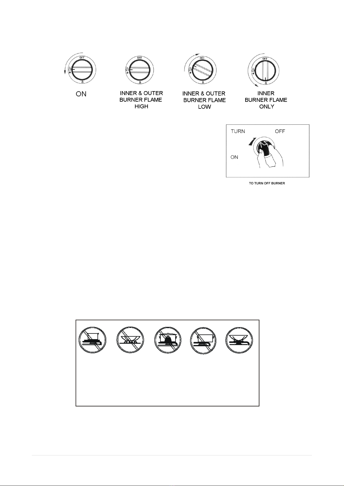
DO NOT PLACE ARTICLES ON OR AGAINST THIS APPLIANCE.
MAINTENANCE.
DO NOT MODIFY THIS APPLIANCE.
Keep the appliance clean regularly by wiping with a damp cloth.
Before checking and maintaining the appliance, make sure the main gas valve is turned off.
Make sure the burner head(s) is/are clean before using the appliance. Use a steel wire brush to
clean the burner if it is heavily clogged. If the burner is heavily clogged, do not use the unit.
Contact Bromic Pty Ltd or an authorized agent for assistance to carry out service and
maintenance. Do not attempt to remove the burner unit(s) yourself.
Check the gas hoses regularly for wear or leaks. If any wear or leaks are presents, please
contact Bromic for replacement.
Do not touch the burner, trivet, tray etc. immediately after use or when in use. This could burn
your hand.
Clean the trivet and tray after each use. Always wipe off spills, do not leave spills to dry on the
surface of the trivet, tray or burner.
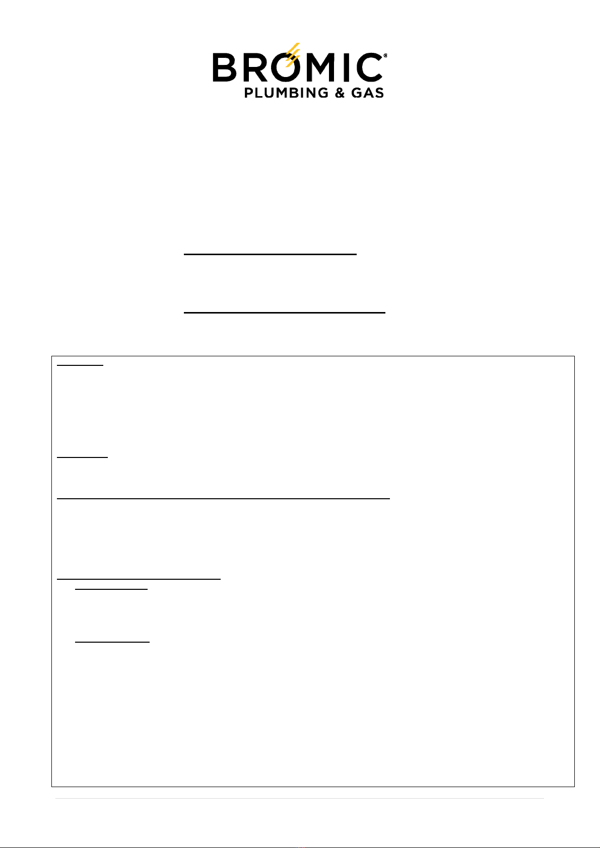
Wash the burner head and burner cap with a moist and soaped sponge or cloth. Do not put
them in cold water immediately after use as thermal shocks could cause cracking.
Always clean off any liquid as soon as it is spilt. This will prevent food remains from sticking to
the hob surface and you will save yourself any unnecessary effort. Do not leave acidic liquids (e.g.
lemon juice, vinegar, etc.) on the hob.
Due to the high temperatures endured, the wok burner and the stainless steel zones (grease drip
tray, burner outline, etc.) can change colour. This is normal. After each use, clean these areas with
a product that is suitable for stainless steel.
SERVICE INSTRUCTIONS FOR AUTHORISED PERSON such as LICENSED GAS FITTER OR
PLUMBER. DO NOT MODIFY THIS APPLAINCE.
Access to components under the hob. Ensure the appliance is cool before attempting any
service and the gas supply is turned off or disconnected.
Disconnect regulator or hose from gas supply. Remove trivet/s, spillage bowls/s and burner
caps. Invert the appliance. The gas connection with regulator (NG) or hose (LP), gas manifold,
burner/s, gas valve/s, thermocouple/s and spark electrode/s are exposed for removal.
To remove the regulator (NG) or hose (LP) disconnect from gas inlet fitting. Replace in reverse
order.
To remove the burner – remove the spring clip retaining the underside of the burner head to
the burner mounting bracket. Drop the burner through the hole vacated by the spillage bowl.
The burner body and primary aeration shutters are accessible to cleaning or adjustment.
Replace in reverse order.
To remove the gas valve inclusive of outer/inner and pilot injector and electrode / electrode
bracket – remove the manifold (2 screws) connecting to the underside of the gas valve.
Remove the control knob and remove the disc (2 screws) securing the gas valve to the front
control fascia. The gas valve, injectors and electrode are accessible for replacement. The
injector outer and inner burner supply, are secured into the gas valve via 9.0mm hex flat. To
access the pilot injector remove the 2 screws securing the electrode bracket to the gas valve.
The pilot injector is secured to the gas valve via 6.0mm hex flat. To replace the electrode
disconnect the HT silicon lead and remove the 2 screws securing the electrode bracket to the
gas valve. Replace in reverse order.

9 | Page Rev4.1
To replace the thermocouple disconnect the quick connect fitting and the earth ring from the
gas valve. The bracket retaining the thermocouple is secured to the burner mounting bracket.
The thermocouple head and threaded body is retained in the thermocouple bracket via two
locking nuts one above and one below the bracket. Remove the top locking nut and remove the
thermocouple. Replace the thermocouple in reverse order. Note the bulb is positioned relative
to the burner port and secured by two 8.0mm (across the flats) x 2.5mm thick hex nuts. The nut
under the bracket is the datum for aligning the bulb tip with the burner port. The top nut secures
onto the upper surface of the bracket. On the replacement thermocouple ensure that the
thermocouple tip is relative to the inner burner port – 6.3 mm above burner port, 3.7 mm
between thermocouple and port, 34.6 mm from top surface of mounting bracket to tip of
thermocouple. Ensure the appliance is tested for gas leakage after servicing.
Burner shutter primary air adjustment;
Natural Gas Main burner outer primary aeration control.
11.48 mm x 2 openings. Primary air shutter in fully open position.
Natural Gas Main burner inner primary aeration control
1.65 mm x 2 openings. Primary air shutter in fully open position.
LP Gas Main burner outer primary aeration control.
8.56 mm x 2 openings. Primary air shutter in fully open position.
LP Gas Main burner inner primary aeration control
12.14 mm x 2 openings. Primary air shutter in fully open position.
TROUBLESHOOTING
Problem Possible Cause Solution
No Ignition
Main Gas Valve is not turned
on.
Air trapped in the gas hose.
Electronic ignition is wet or
dirty.
The safety valve is not open.
Turn off the gas valve once and then turn it on fully.
Repeat the ignition process until all air in the hose is purged
completely.
Clean and wipe the electrode with a dry cloth.
Push in the ignition knob and turn it anti-clockwise until a click
sound is heard. Ensure the burner has been lit. Press the ignition
knob for 3-4 seconds and release the knob.
Burner will
not stay
alight
The thermocouple is wet or
dirty.
Clean the thermocouple. If the burner does not stay alight after
cleaning the thermocouple. Contact Bromic or an authorised
agent for service/repair.
DO NOT ATTEMPT TO REPAIR IT YOURSELF.
Gas Leaking
Failure of the gas valve.
Contact your Bromic or an authorised agent for service/repair.
DO NOT ATTEMPT TO REPAIR IT YOURSELF.
Incomplete
Combustion
(Yellow
Flame)
Aeration shutters are not
properly adjusted.
Burner is not properly
assembled.
Flame holes of the burner
are clogged.
Nozzle is clogged.
Contact a gas fitter to adjust the aeration shutters to achieve the
optimum air/gas intake ratio.
Position the burner head/s properly.
Clean the burner head and the burner cap.
Contact Bromic or an authorised agent for service/repair.
DO NOT ATTEMPT TO REPAIR IT YOURSELF.

10 | Page Rev4.1
TECHNICAL SPECIFICATION
Natural Gas
Model Number DC100NG-S DC200NG-S
Heat Capacity (MJ/hr) 15.00 30.00
Injector
size (mm)
Outer 1.65 1.65
Inner 0.70 0.70
pilot 0.90 0.90
Dimensions (mm) (H)145x(W)300x(D)382 (H)145x(W)720x(D)382
Net Weight (kg) 3.7 6.6
Gas Type NATURAL GAS
Gas Pressure (kPa) 1.00
Gas Fitting ¼” BSPM 600 coned
Ignition System Piezo-electric
Country of Origin China
AGA Approval No. 7092 G
LP Gas
Model Number DC100-S DC200-S
Heat Capacity (MJ/hr) 14.00 28.00
Injector
size (mm)
Outer 0.95 0.95
Inner 0.45 0.45
pilot 0.50˜0.68 0.50˜0.68
Dimensions (mm) (H)145x(W)300x(D)382 (H)145x(W)720x(D)382
Net Weight (kg) 3.7 6.6
Gas Type UNIVERSL LP GAS
Gas Pressure (kPa) 2.75
Gas Fitting 5/8-18 UNF thread
(
known as 3/8 SAE male fittin
g)
Ignition System Piezo-electric
Country of Origin China
AGA Approval No. 7092 G
Bromic Pty. Ltd and their appointed agents will not be liable in respect of any misuse, which is not in accordance with the
instructions and precautions specified in this booklet.
BROMIC PTY LTD
10 Phiney Place Ingleburn NSW 2565
Technical Assistance Services
For service, spare parts and repairs, contact Customer Service + 61 2 9426 5222 or
Please provide the appliance model number and serial number. This information is given on the label
located on the burner.

11 | Page Rev4.1
WARRANTY
WARRANTY PERIOD
Bromic Pty Limited (‘Bromic’) warrants to the original purchaser (‘the Purchaser) of this Bromic ‘Ring Burner’, that the
Ring Burner will be free from defects or faults in materials and/or workmanship for 12 months from the date of purchase
(‘the Warranty Period’).
WARRANTY CONDITIONS
Subject to the following conditions, if a defect or fault in parts or workmanship is found during the Warranty
Period, Bromic will replace or repair the Ring Burner or part of it (at its option) without charge to the Purchaser. Bromic
may undertake any repairs or nominate an authorised repair agent to do so.
The Purchaser must retain the original purchase docket and produce it to Bromic at the time of making a claim under this
Warranty.
The Purchaser must report any potential fault and/or defect to Bromic as soon as possible after discovery of
the potential fault and/or defect.
The requirement for repair or replacement of the Ring Burner must have arisen solely from faulty and/or defective
materials and/or workmanship and must not be due to misuse, neglect, accident, improper installation, unauthorised
modification, unauthorised attempted repair, failure to comply with the Ring Burner’s instruction manual and/or markings
on the Ring Burner or other abuse which, in the reasonable opinion of Bromic, was caused by the Purchaser or any
agent or employee of the Purchaser.
Bromic is not liable for any transport costs incurred in connection with a warranty investigation or service of
the Ring Burner within the Warranty Period.
Bromic reserves its right to invoice the Purchaser for any investigation or service (including parts and labour) which is
found not to be connected to a warranty issue.
Bromic is not liable for any incidental or consequential loss or damage arising from any cause whatsoever
including but not limited to loss or damage arising from misuse of the Ring Burner, neglect, accident, improper
installation, unauthorised modification, unauthorised attempted repair, failure to comply with the Ring Burner’s instruction
manual and/or markings on the Ring Burner and/or any cause independent of human control that occurs after the
Product has left the control of Bromic.
CLAIMING UNDER THE WARRANTY OR CONSUMER GUARANTEES
Please contact Bromic as soon as possible after discovery of a potential defect and/or fault with the Ring Burner to
arrange for it to be tested and/or serviced.
All warranty enquiries and/or claims should be directed to Bromic’s Head Office via its postal address -
P0 Box 414, Ingleburn Post Shop NSW 1890 or by telephoning 1300 276 642 (within Australia) or sending a
fax to +61 2 9748 4289.
CONSUMER GUARANTEES UNDER THE ACL
In addition to the Warranty extended by Bromic to the Purchaser, the Australian Consumer Law requires that Bromic
provide the following additional guarantees to consumers (as that word is defined by the Competition and Consumer Act)
in respect of consumer goods (as defined by that Act) supplied in Australia.
Our goods come with guarantees that cannot be excluded under the Australian Consumer Law. You are
entitled to a replacement or refund for a major failure and for compensation for any other reasonably
foreseeable loss or damage. You are also entitled to have the goods repaired or replaced if the goods fail to be of
acceptable quality and the failure does not amount to a major failure.

12 | Page Rev4.1
Call 1300 276 642 (1300 BROMIC)
or +61 2 9426 5222
Email us [email protected]
Visit www.bromic.com/plumbing
This manual suits for next models
3
Table of contents
Popular Burner manuals by other brands

CIB UNIGAS
CIB UNIGAS C92A Manual of installation - use - maintenance

BETHLEHEM
BETHLEHEM S.S. MINNOW BURNER operating instructions

Riello
Riello P 140 T/G Installation, use and maintenance instructions

elco
elco VL 04.540 DP operating instructions

REMS
REMS Macho instruction manual

Riello
Riello G20I Installation, use and maintenance instructions

Bentone
Bentone BG 700 M Installation and maintenance instruction

Ecoflam
Ecoflam BLU 1500.1 PAB manual

Riello
Riello RX 500 S/PV Modulating operation

Weil-McLain
Weil-McLain Gas Burner specification

CIB UNIGAS
CIB UNIGAS Idea Series Manual of installation - use - maintenance

Unigas
Unigas N880X-FGR Manual of installation - use - maintenance