Broncolor HMI F1600 User manual

Creative lighting, precision, inspiration, style and emotion – even in the age of digital
photography, none of these facets have lost in importance. broncolor offers workshops
of 2 and 3 days. Are you interested? You can apply online on our website www.bron.ch under
broncolor / Lighting / Workshops
Kreative Lichtführung, Präzision, Inspiration, Styling und Emotionen – auch im Zeitalter der
digitalen Fotografie haben sich die Stichworte nicht geändert. broncolor bietet verschiedene
Workshops von 2- oder 3-tägiger Dauer an. Sind Sie interessiert? Sie können sich Online anmelden
auf unsere Website www.bron.ch unter broncolor / Lighting / Workshops
Utilisation créative de la lumière, précision, inspiration, styling et émotions – ces notions
fondamentales ont gardé toute leur importance à l’ère de la photographie numérique.
broncolor propose différents workshops de 2 ou 3 jours. Etes-vous intéressé? Vous pouvez
vous inscrire en ligne sur notre site internet www.bron.ch, sous la rubrique
broncolor / Lighting / Workshops
BRONCOLOR LIGHTING COURSES
BRONCOLOR LICHTSCHULUNG
STAGE DE FORMATION À L‘ÉCLAIRAGE BRONCOLOR
Bron Elektronik AG
CH-4123 Allschwil 1/Switzerland
www.bron.ch
|| Urs Recher, Switzerland
BA108.00 | Printed in Germany 02/15
HMIF1600 | 800.1600
Operating instructions | Bedienungsanleitung | Mode d‘emploi

|| Sandro Bäbler, Switzerland
|| Urs Recher / model: Deborah Frey, Germany


OPERATING INSTRUCTIONS | BRONCOLOR HMI F1600
HMI 800.1600
Before use
Please read all the information contained in these operating instructions carefully. They contain
important instructions for use, safety and maintenance of the appliance. Keep these operating
instructions in a safe place and pass them on to further users if necessary. Observe the safety
instructions.
Contents Page
Attention! Important safety instructions Read carefully before starting up! 6
1. Starting up 7
2. Fitting or changing a bulb 8
3. Mounting and removing reflectors and adapters 8
4. Fitting and removing accessories 8
5. Focusing 9
6. Operating the lamp with a Para 9
7. Operating modes 9
8. Display on ballast unit 10
9. Protective circuits in the ballast unit 10
10. Fault diagnosis table 11
11. Operating broncolor ballast units from a motor-generator set 11
12. Controls and display elements ballast unit HMI 800.1600 12
13. Technical data, ballast unit HMI 800.1600 12
14. Controls and display elements, lamp HMI F1600 14
15. Technical data, lamp HMI F1600 16
16. Order numbers for spare parts and accessories 16
17. Environmental protection information 16

6
ATTENTION! IMPORTANT SAFETY INSTRUCTIONS
HMI F1600 | HMI 800.1600
> Read carefully before starting up!
> The equipment should be used exclusively by qualified personnel.
> Use only a complete and undamaged connection cable. Position the cable so that it will not be
tripped over or make contact with hot surfaces. If an extension cable is necessary, ensure that a
cable is used with a current rating at least equal to that of the ballast. Cables rated for less amper-
age than the appliance may overheat.
> For safety reasons, the ballast unit may only be operated with an earthed mains (AC-line) plug.
When the appliance is switched on, the yellow LED light must illuminate.
> Avoid incorrect use of any kind and be particularly careful not to obstruct the natural circulation of
air that keeps the lamp and ballast unit cool.
> The ballast unit and lamp must not be exposed to moisture. This could cause dangerous electric
discharges on contact!
> To minimise the risk of fire, electric shock, or injury to persons, use exclusively accessories
recommended by the manufacturer.
> The equipment must not be used in explosion-hazard areas.
> The lamp and accessory attachments may heat up to high temperatures. Please handle with care.
> When these units are used suspended, they must always be secured with a steel cable.
> To protect against the effects of radiated heat, the lamp must not be directed at flammable
surfaces and/or surfaces sensitive to heat or any objects from less than a minimum distance of
2 meters.
> In order to achieve maximum service life from the lamp, the heating up process of approx.
1 minute should not be interrupted.
> Use the lamp only with a reflector or adapter with undamaged safety glass. Lamps can burst.
The safety glass will retain hot fragments.
> Like natural daylight, HMI/MSR light contains a certain proportion of UV radiation. The safety glass
reduces the UV content to safe levels for normal operating distances. When used at a close
operating distance, limit the exposure time of unprotected skin.
> Before replacing fuses or the lamp, disconnect the ballast unit from the mains power supply.
> Before the ballast unit is cleaned or serviced, and while it is not in use, it must be switched off
and completely disconnected from the mains supply. Never pull on the cable itself: pull only on the
plug body.
> Allow time for the ballast unit and lamp to cool before you stow them.
> Units with noticeable damage or which have been dropped must not be started up. Contact a
broncolor service station. Service work or repairs must always be carried out by a specialist.
> Only original spare parts must be used to guarantee long-term mechanical and electrical
operating safety. Incorrect assembly can cause dangerous contact voltages, even on connected
units.

7
1. STARTING UP
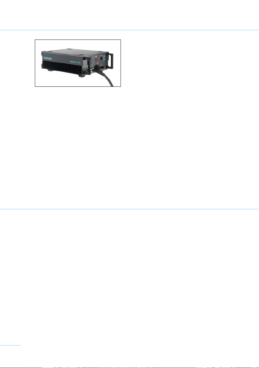
The ballast unit HMI 800.1600 is a flicker-free electronic ballast units which are made for mains
voltages from 90 V to 265 V. They adjust automatically to the mains (AC-line) voltage applied.
The unit is suitable for operation with hot-restrike (HR) lamps. This means that the lamp may be
switched on again at any time while hot, making waiting time unnecessary. For safety reasons,
the high ignition voltages required for this purpose call for a faultless earth conductor. For this
reason the unit must only be connected to a power supply with an earthed mains plug. Correct
functioning of the earth conductor is indicated by the control lamp (3).
Step 1
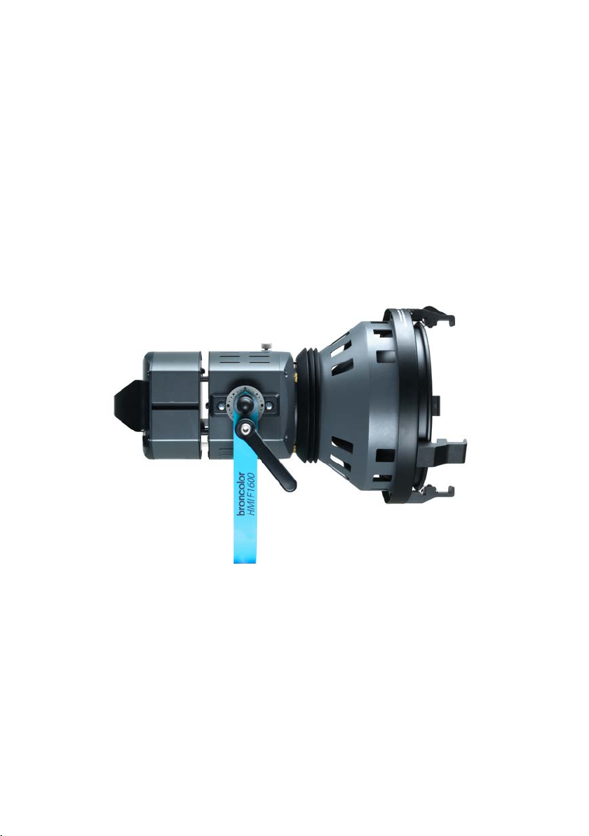
Fit a compatible bulb to the lamp (see Section 2: Fitting or changing a bulb) and a reflector, an
adapter for a Softbox or Para (see Section 3: Mounting and removing reflectors and adapters). The
lamp is equipped with an integral safety switch (17), and can only be operated when a reflector or
an adapter is mounted. When it is used with an adapter, the focusing wheel (11) must be turned
to the “Bare Bulb” position (bulb as far forwards as it will go) so that the safety switch is actuated
and the bulb can be fired.
Step 2
Connect the lamp to the ballast unit, and the ballast unit to the earthed mains supply. Switch on
the main switch (2) and check whether the earth control LED (3) illuminates. If this is not the case,
for safety reasons disconnect the ballast unit immediately from the mains and check the earth
conductor.
Step 3
Operate switch (9) on the lamp and press button (4) on the ballast unit. The bulb fires and starts
operating. By operating the switch (9) on the lamp or on the ballast unit (4), the light can be
switched off again.
The ballast unit has an automatic warming-up circuit, which heats the bulb quickly to its operating
temperature. Except in an emergency avoid switching off the unit during the warming-up phase,
because this shortens the life of the bulb. The optimum colour temperature is reached after about
one minute.
Should the bulb fail to trigger, the ballast unit will switch off the ignition sequence after 2 seconds,
and button (4) on the ballast unit blinks (see Section 7). To make another attempt to start, press
the button (4) on the ballast unit or (9) on the lamp. To protect the igniter circuit, this is blocked
for 30 seconds after about ten attempts at ignition. Afterwards further ignition attempts are pos-
sible. Take care that the ventilation slots are not obstructed on either the ballast unit or the lamp.
Step 4
The output regulator (8) on the ballast unit can be used to set the desired light output (setting
range 50 % –100 %). When setting the output, it is important to remember that, depending on the
bulb used, the colour temperature can change slightly with the output. When the bulb is switched
on, the output is automatically set to the maximum so that the bulb heats up as quickly as pos-
sible. The duration of this depends on the bulb temperature when it is switched on, and is likely
to be between 5 and 60 seconds. At the end of this period, the unit adjusts automatically to the
setting of regulator (8).

8
2. FITTING OR CHANGING A BULB
Before fitting or changing a bulb, the lamp must be disconnected from the ballast unit. Then
remove the reflector or adapter.
Fitting: Turn the focusing wheel (11) on the lamp to its stop in the “flood” (bare bulb) position. The
bulb socket is now extended as far as it will go. Open the two cover plates (15) and push the bulb
into the socket to the stop. Afterwards, take care that the cover plates are completely closed again.
Removing: Caution: the bulb is hot! Allow the bulb to cool before changing it!
Turn the focusing wheel (11) on the lamp to its stop in the “flood” position. The bulb socket is now
extended as far as it will go. The bulb can now be pulled out. The two cover plates (15) are spring-
loaded and can be opened.
3. MOUNTING AND REMOVING REFLECTORS AND ADAPTERS
Mounting: Undo the retaining screw (10) on the lamp. Align the mounting pin on the reflector
with the appropriate opening (20), then position the accessory and turn it 10° clockwise until
you hear the security pin (16) latch. Take care not to damage the bulb while dismounting an
accessory!
Removing: Loosen the retaining screw (10) on the lamp, then pull it straight backwards and
hold it. Turn the reflector through 10° until it is released. Remove the reflector or adapter
straight forwards. Take care not to damage the bulb while dismounting an accessory!
Attention: When operating with an adapter for a Para or Softbox, the focusing wheel (11) must
be turned to the “flood” (bare bulb) position (bulb as far forwards as it will go) so that the safety
switch is actuated and the bulb can be fired.
For operation with Softboxes an adapter, Art. No. 43.155.00 is available as an accessory.
4. FITTING AND REMOVING ACCESSORIES
Unlatch the movable jaw (28) by pushing it against the spring and fold it outwards. The four-
leaf barn doors (27, 34) and, where fitted, a scrim ring (26) can now be introduced from above
into the outer mounting grooves of the fixed claws (30). If a further accessory, such as a filter
or diffusion lens (25, 33) is required, it can be fitted in the inner mounting grooves. Fold the
moving jaw (28) down so that it latches. Turn the four-leaf barn door to make sure it is securely
mounted.

9
5. FOCUSING
The degree of focusing can be adjusted using the focusing wheel (11) on the rear face of the lamp.
The adjustment function is indicated with “flood” (bare bulb) and “spot” markings. When the lamp
is operated with an Open Face or a PAR reflector and a Fresnel lens fitted, then the entire focus-
ing range can be used.
6. OPERATING THE LAMP WITH A PARA
To operate the lamp in a broncolor Para reflector, an adapter (35), Art. No. 43.156.00 is required.
It is recommended that the lamp’s yoke (21) is removed completely. To remove it, undo the
screws (18) and pull the two carrier plates with the yoke towards the handle. The complete
yoke can now be removed. Please ensure that the maximum permissible output of the Para
reflector is not exceeded.
7. OPERATING MODES
The ballast unit has three different operating modes, which can be selected by pressing the
button (5) on the ballast unit. The mode selected is indicated by illumination of an LED (5 a
–
c):
low noise: For extremely noise-sensitive shoots, up to 100 fps
optimal: For “normal” shoots at up to 800 fps
high speed: For high-speed shoots at up to 2000 fps

10
8. DISPLAY ON BALLAST UNIT
Mains switch (2)
Illuminated: mains voltage is present. The unit is switched on.
Not illuminated: The unit is switched off or not connected to the mains voltage.
Indicator for earth conductor (3)
Illuminated: The unit is switched on and the earth conductor is correctly connected.
Not illuminated: The unit is switched off or the earth conductor is not correctly connected.
Lamp control display (4)
Illuminated: The lamp is switched on and the unit is functioning correctly.
Not illuminated: The lamp and/or the ballast unit is switched off or not connected to the mains
supply.
(5a–c) operating mode display
(7a, b) display shows that the lamp has been identified
The HMI 800.1600 ballast unit features monitoring electronics with detailed fault diagnosis.
Overvoltage protection: If the applied voltage is greater than 260 V, the ballast unit either
switches off automatically, or cannot be switched on. Button (4) blinks to indicate this.
Low-voltage protection: If the applied voltage is below 90 V, the ballast unit either switches off
automatically, or cannot be switched on. Button (4) blinks to indicate this.
Current limitations: When a 1600 W lamp is operated on a mains voltage below 95V, the lamp
output is automatically reduced to prevent the current exceeding 18 A. Button (7a) blinks to
indicate this. Should the voltage rise above 95 V again during operation, the output will remain
unchanged at the reduced level, so as to avoid continual changes in lighting.
Thermal monitoring: If the operating temperature of the unit is exceeded, the ballast unit
automatically regulates the output gradually down to max. 50 %. This lowering of the output
allows the user time to recognise the situation and to prevent or delay a total shutdown. If a
shutdown occurs, for safety reasons, the unit does not automatically switch on again. The lamp
must be switched on again manually.
Igniter circuit protection: If the bulb fails to trigger, ignition is blocked for 30 seconds after
about ten attempts at ignition in succession.
9. PROTECTIVE CIRCUITS IN THE BALLAST UNIT

11
Fault detected How to
reset
Start/Stop
(4)
high speed
(5a)
normal
(5b)
low noise
(5c)
800W
(7a)
1600W
(7b)
Earth
(3)
Short circuit Restart blinks blinks off off (on) (on) on
Bulb goes out Restart blinks off blinks off (on) (on) on
Wrong lamp
detected
Restart blinks off off blinks (on) (on) on
Supply voltage
over 265 VAC
Restart blinks blinks blinks off (on) (on) on
Supply voltage
below 85 VAC
Restart blinks blinks off blinks (on) (on) on
Operating
temperature
exceeded
Allow to
cool
blinks off off off (on) (on) on
More than 10
ignition attempts
Allow to
cool
blinks off blinks blinks (on) (on) on
Technical fault Service
station
blinks blinks blinks blinks blinks blinks on
10. FAULT DIAGNOSIS TABLE
Ballast units are suitable for operation with motor-generator sets, in so far as the voltage un
der
all load conditions (including capacitive loads) is within the tolerance limits of 200 – 260 V or
95 – 135V. Experience shows that this usually requires electronically-stabilised motor-generators.
Unstabilised motor-generators can produce voltage peaks of 300 V and over. This may cause
damage for which Bron Elektronik AG accepts no liability.
11. OPERATING BRONCOLOR BALLAST UNITS FROM A MOTOR
GENERATOR SET
9. PROTECTIVE CIRCUITS IN THE BALLAST UNIT

12
12. CONTROLS AND DISPLAY ELEMENTS
BALLAST UNIT HMI 800.1600
1 Grip
2 Main switch 0/I with integral fuse
3 Earth conductor indicator
4 Button, lamp On/Off
5 Button for selecting operating mode
5a–c Indicators for selected operating mode
6 Mains cable
7 Lamp plug socket
7a–b Indicators show which lamp has been identified
8 Rotary knob for adjusting output (dimmer)
13. TECHNICAL DATA, BALLAST UNIT HMI 800.1600
Supply power rating 1800 VA
Mains voltage 90 – 265 V
Mains frequency 50/60 Hz
Current draw 20 A (90 VAC), 15 A (120 VAC), 8 A (230 VAC)
Power factor 99 % at 110 V / 95 % at 230 V
Lamp frequency square-wave 50, 400, 1000 Hz
Regulation zone 50
–
100 %
Lamp detection automatic
Start-up characteristics cold start and hot restrike capability
Dimensions (lxbxh) 360 x 240 x 120 mm (142 x 94 x 47")
Weight 6.9 kg (15.2 lbs)

13

14
14. CONTROLS AND DISPLAY ELEMENTS, LAMP HMI F1600
9 On/Off switch
10 Retaining screw
11 Focusing wheel
12 Lamp cable
13 Clamping disc
14 Yoke locking handle
15 Cover plates
16 Security pin
17 Safety switch
18 Screw for removing the yoke (e.g. when mounting a Para)
19 Carrier plate for yoke
20 Slots for reflector or Softbox adapter
21 Yoke
22 28 mm (1.1") stand spigot with 16 mm (0.6") bore
23 Retaining screw
24 PAR reflector
25 Diffusion lens
26 Scrim ring
27 Four-leaf barn door for PAR reflector
28 Movable jaw
29 Filter clamps
30 Fixed jaws
31 Safety glass
32 Open Face reflector
33 Diffusion filter / conversion filter
34 Four-leaf barn door for Open Face reflector
35 Adapter for Softboxes
36 Adapter for Paras
37 Safety glass sleeve
38 16 mm (0.6") mount

15

16
15. TECHNICAL DATA, LAMP HMI F1600
Output 1600 W
Bulb socket G22
Focusing range, Open Face reflector 19° –58°
Dimensions (lxbxh) 250 x 302 x 145/408 mm (98 x 119 x 57/161")
Weight
4.3 kg (9.5 lbs)
16. ORDER NUMBERS FOR SPARE PARTS AND ACCESSORIES
Ballast unit HMI 1600 41.104.XX
Lamp F1600 42.108.00
Open Face reflector 43.150.00
Four-leaf barn door for Open Face reflector 43.151.00
Diffusion filter for Open Face reflector 43.152.00
Conversion filter for PAR reflector 43.153.00
PAR reflector 43.140.00
Four-leaf barn door for Open Face reflector 41.141.00
Scrim ring 43.139.00
PAR lens set (4 off) 43.144.00
PAR lens NSP 43.145.00
PAR lens MFL 43.146.00
PAR lens WFL 43.147.00
PAR lens VWFL 43.148.00
Fresnel lens 43.149.00
Bag for 5 filters or lenses 43.138.00
1600 W bulb G.E. CSR1600 SE/HR/UVC 44.107.00
1600 W bulb Sylvania BA1600 SE/HR/UVC 44.108.00
Lamp cable 7.5 m 44.202.00
Lamp cable 10 m 44.203.00
Lamp cable 20 m 44.204.00
Adapter for Softboxes 43.155.00
Adapter for Paras 43.156.00
Carrying case with wheels for complete kits 46.101.00
Carrying case for Para Kit 46.102.00
17. ENVIRONMENTAL PROTECTION INFORMATION
At the end of its useful life, this product may not be disposed of as normal
household waste, but should be taken to a collection point for the recy-
cling of electrical and electronic appliances. The materials are recyclable
according to their markings. By re-use, recycling, or other form of using
old appliances you are making an important contribution to the protection
of our environment. Please ask your sales partner or local authorities for
the appropriate disposal point.

17

18

19
BEDIENUNGSANLEITUNG | BRONCOLOR HMI F1600
HMI 800.1600
Vor dem Benutzen
Bitte lesen Sie alle in dieser Bedienungsanleitung aufgeführten Informationen aufmerksam durch.
Sie geben Ihnen wichtige Hinweise für den Gebrauch, die Sicherheit und die Wartung des Gerätes.
Bewahren Sie diese Gebrauchsanweisung sorgfältig auf und geben Sie diese gegebenenfalls an
Nachbenutzer weiter. Beachten Sie die Sicherheitshinweise.
Inhaltsverzeichnis Seite
Achtung! Wichtige Sicherheitshinweise Vor Inbetriebnahme unbedingt lesen! 20
1. Inbetriebnahme 21
2. Brenner einsetzen oder wechseln 22
3. Aufsetzen oder Abnehmen der Reflektoren und Adapter 22
4. Aufsetzen und Abnehmen des Zubehörs 22
5. Fokussierung 23
6. Betrieb der Leuchte mit Para 23
7. Betriebsarten 23
8. Anzeigen am Vorschaltgerät 24
9. Schutzeinrichtungen im Vorschaltgerät 24
10. Fehlerdiagnosetabelle 25
11. Betrieb von broncolor Vorschaltgeräten an Motor-Generatoren 25
12. Bedienungs- und Anzeigeelemente Vorschaltgerät HMI 800.1600 26
13. Technische Daten Vorschaltgerät HMI 800.1600 26
14. Bedienungs- und Anzeigeelemente Leuchte HMI F1600 28
15. Technische Daten Leuchte HMI F1600 30
16. Bestellnummern der Einzelteile und Zubehör 30
17. Hinweis zum Umweltschutz 30

20
ACHTUNG! WICHTIGE SICHERHEITSHINWEISE
HMI F1600 | HMI 800.1600
> Vor Inbetriebnahme unbedingt lesen!
> Die Ausrüstung eignet sich ausschliesslich für die Verwendung durch Fachpersonal.
> Verwenden Sie nur intakte Anschlusskabel. Achten Sie beim Verlegen von Kabeln darauf, dass
diese keine heissen Teile berühren und für Personen keine Stolpergefahr darstellen. Falls ein
Verlängerungskabel nötig ist, so muss es für das zu versorgende Vorschaltgerät ausreichend di-
mensioniert sein. Kabel, die nicht für die betreffende Stromstärke ausgelegt sind, können sich
überhitzen.
> Aus Sicherheitsgründen darf das Vorschaltgerät nur an Netzsteckern mit Erdanschluss betrieben
werden. Bei eingeschaltetem Geräteschalter muss die grüne LED-Anzeige (3) brennen.
> Vermeiden Sie jegliche Art von unsachgemässem Gebrauch und achten Sie insbesondere auch
darauf, dass die natürliche Zirkulation der Kühlung an Leuchte und Vorschaltgerät nicht behindert
wird.
> Vorschaltgerät und Leuchte dürfen nicht Feuchtigkeit ausgesetzt werden. Dabei können berüh-
rungsgefährliche Spannungsentladungen entstehen.
> Um die Gefahr eines Feuers, eines elektrischen Schlages oder einer Verletzung zu vermeiden,
verwenden Sie ausschliesslich das vom Hersteller empfohlene Zubehör.
> Die Ausrüstung darf nicht in explosionsgefährdeter Umgebung eingesetzt werden.
> Die Leuchte und das Vorsatzzubehör können hohe Temperaturen annehmen. Bei der Handhabung
ist entsprechende Vorsicht geboten.
> Werden die Geräte hängend betrieben, müssen sie immer mit einem Stahlseil gesichert werden.
> Mit Rücksicht auf die Wärmestrahlung darf die Leuchte nur in einem Minimalabstand von 2 Metern
gegen brennbare und/oder wärmeempfindliche Oberflächen oder Gegenstände gerichtet werden.
> Damit die optimale Lebensdauer des Brenners erreicht wird, soll der Aufheizvorgang von ca. einer
Minute nicht abgebrochen werden.
> Die Leuchte nur mit Reflektor oder Adapter mit intaktem Schutzglas betreiben. Brenner können
platzen. Das Schutzglas verhindert ein Herausfallen von heissen Splittern.
> HMI/MSR-Licht enthält, ähnlich wie natürliches Tageslicht, einen gewissen Anteil an UV-Strah-
lung. Das Schutzglas reduziert den UV-Anteil für normale Einsatzdistanzen auf ungefährliche
Werte. Für Einsatz im Nahbereich ist die Bestrahlung ungeschützter Haut zeitlich zu beschränken.
> Vor dem Auswechseln des Brenners ist das Vorschaltgerät vom Netz zu trennen.
> Bevor Sie das Gerät reinigen oder warten, bzw. wenn es nicht gebraucht wird, muss das Vorschalt-
gerät unbedingt ausgeschaltet und vom Netz getrennt werden. Zum Ausziehen nie am Kabel
selber ziehen, sondern immer direkt am Steckergehäuse.
> Lassen Sie das Vorschaltgerät und die Leuchte abkühlen, bevor Sie diese verstauen.
> Geräte, die fallengelassen wurden oder erkennbare Schäden aufweisen, dürfen nicht in Betrieb
genommen werden. Wenden Sie sich an eine broncolor Servicestelle. Service- oder Reparaturar-
beiten immer durch eine Fachperson ausführen lassen.
> Um die mechanische und die elektrische Betriebssicherheit zu gewährleisten, dürfen nur Original-
ersatzteile verwendet werden. Bei unsachgemässem Zusammenbau können selbst am geschlossenen
Gerät gefährliche Berührungsspannungen auftreten.
This manual suits for next models
1
Table of contents
Languages:
Other Broncolor Flashlight manuals