Brother LX-200 User manual

SERVICE MANUAL
MODEL: LX-200/LX-900/LX-910D
REVISED EDITION May, 2000

Unauthorized copying of all or part of the contents of this manual is prohibited.
The contents of this manual may change without notice.

INTRODUCTION
This Service Manual describes the Cool Laminator LX-200/900/910D specifications, operating
principles of the mechanisms, disassembly and reassembly procedures, and maintenance and
troubleshooting procedures.
This Service Manual is intended for use by trained technicians. It is not intended for use by the
user.
The manual is divided into the following chapters.
Chapter 1. Specifications
Chapter 2. Mechanism
Chapter 3. Disassembly Procedures
Chapter 4. Reassembly Procedures
Chapter 5. Electronic Controllers
Chapter 6. Maintenance
Chapter 7. Troubleshooting
Appendix Main PCB Circuit Diagram

Chapter 1.
SPECIFICATIONS

1-i
CONTENTS
Chapter 1. SPECIFICATIONS
1.1 Mechanical Specifications.................................................................................................1-1
1.1.1 Appearance...........................................................................................................1-1
1.1.2 Operating Panel ....................................................................................................1-1
1.1.3 Indicators...............................................................................................................1-2
1.2 Electrical Specifications ....................................................................................................1-2
1.2.1 Power Supply........................................................................................................1-2

1-
1
1.1 Mechanical Specifications
1.1.1 Appearance
[1] External dimensions (W x D x H) 357 mm x 293 mm x 195 mm
[2] Mass Approx. 4.6 kg (main unit only)
357 mm
293 mm
195 mm
Fig. 1.1-1Appearance
1.1.2 Operating Panel
[1] Number of Keys 5(Power switch, Cut key, Feed key,
Start/Stop button, Cutting mode selector)
[2] Key Arrangement
Power switch
Cut key (Horizontal)
Feed key
Start/Stop button
Cutting mode selector
Fig. 1.1-2Key Arrangement

1-
2
1.1.3 Indicators
[1] Positions Start/Stop button LED indicators (red, green, orange)
1.2 Electrical Specifications
1.2.1 Power Supply
[1] Power supply Commercial power supply (locally available power supply).
Converted to DC by the AC adaptor.

Chapter 2.
MECHANISMS

i
CONTENTS
Chapter 2. MECHANISMS
2.1 Mechanical Operating Principles......................................................................................2-1
2.1.1 Description of Mechanisms (Border Mode)..........................................................2-1
2.1.2 Feed and Compression Mechanisms...................................................................2-2
2.1.3 Cutter Mechanism (Border Mode)........................................................................2-4
2.1.4 Paper Size Detector Mechanism..........................................................................2-6
2.1.5 Trimming Mechanism...........................................................................................2-8
2-
1
2.1 Mechanical Operating Principles
2.1.1 Description of Mechanisms (Border Mode)
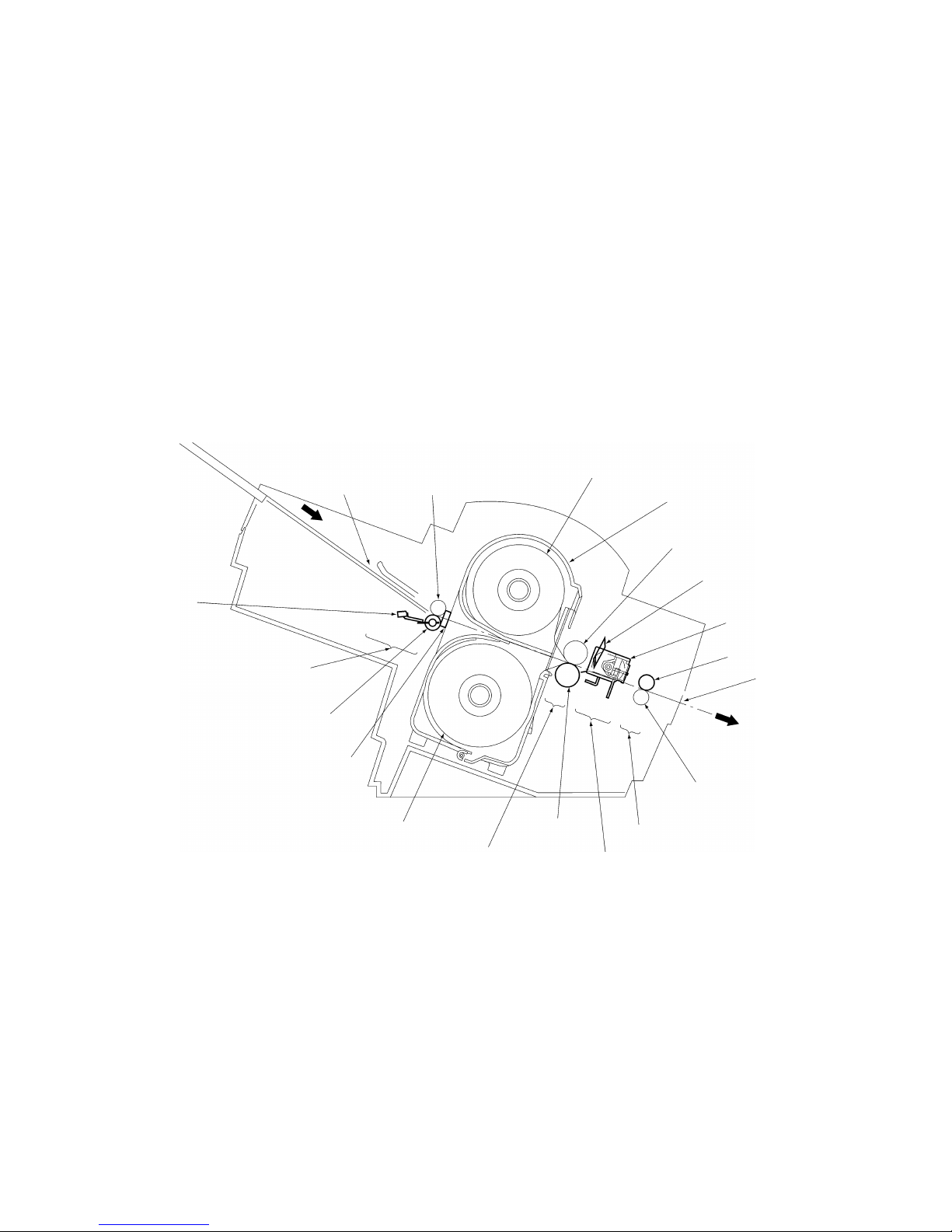
1. When a document is inserted into the paper loading gate, the paper feed rollers feed
it to the driving roller.
2. As the document passes between the paper feed rollers, the paper size detector
determines its size (length and width).
3. When the document passes between the film cartridges it is sandwiched between
the upper and lower films in the compression-feed area, where the films and
document are compressed between the driving roller and sub-roller.
4. The compressed document and film is fed to the cutting area, where it is cut to the
document size detected by the paper size detector with borders added. It is then
transported to the next stage.
5. The laminated document is fed out of the eject gate by the paper eject rollers.
Paper loading gate Paper feed sub-roller Roll film (upper)
Film cartridge
Sub-roller
Y-cutter blade
X-cutter unit
Paper eject roller
Eject gate
Paper eject sub-roller
Ejecting area
Cutting area
Driving roller
Compression-feed area
Roll film (lower)
Paper width detector
Paper feed roller
Paper loading area
Paper length
detector
Fig. 2.1-1Description of Mechanisms
2-
2
2.1.2 Feed and Compression Mechanisms
The feed and compression mechanism controls the motor drive to feed the document
into the film cartridge, compression-feed the films, and eject the laminated document.
When no compression-feed is applied while feeding a document into the film cartridge
or ejecting a laminated document, the LF motor rotates clockwise and the motor drive is
transmitted via gears to the paper feed roller and paper eject roller.
At this time, the planet gear (A) is free from the drive gear (A), such that the drive is not
transmitted to the driving roller.
During compression-feeding of the films, LF motor rotates counterclockwise to move the
planet gear (A) against the drive gear (A), such that the drive from the LF motor is
transmitted to the driving roller.
Also, planet gear (B) moves against the drive gear (B) and planet gear (C) moves
against the drive gear (C), such that the LF motor drive continues to be transmitted to
the paper feed roller and paper eject roller, without changing the direction of roller
rotation.
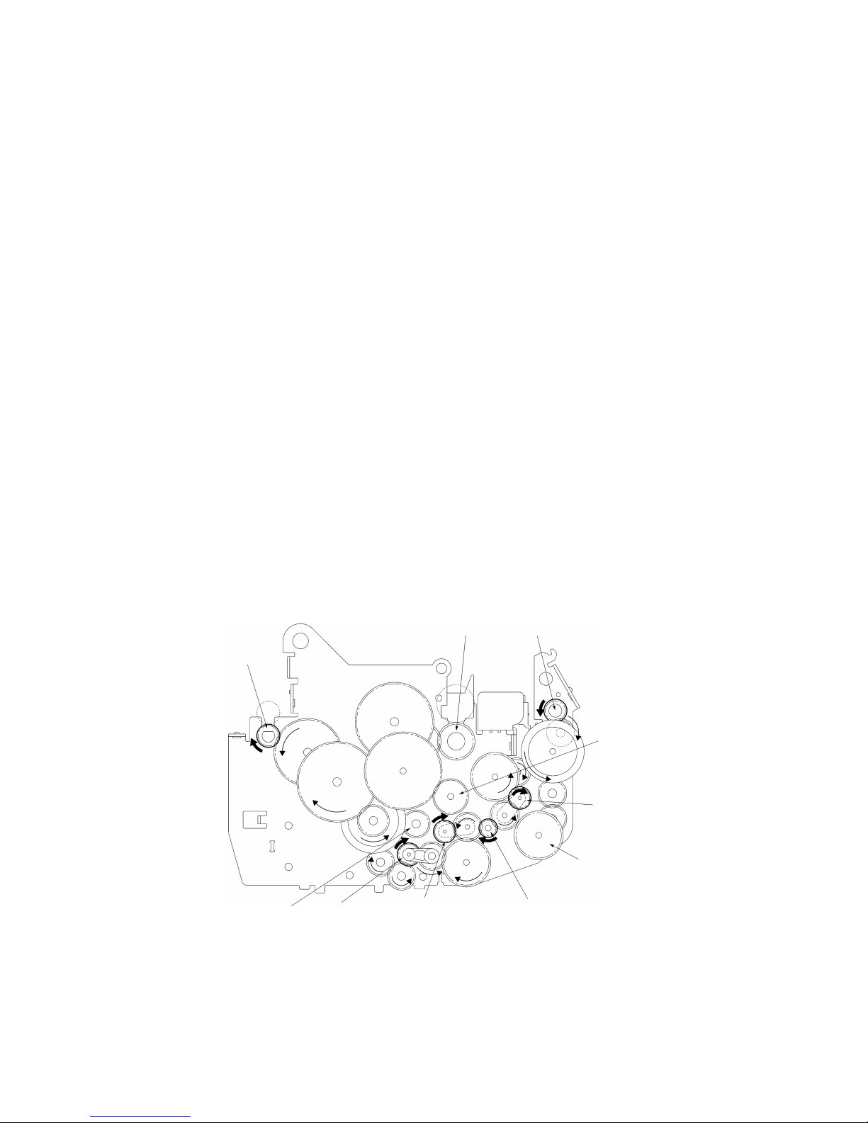
•Operation when Feeding Document into the Film Cartridge or when Ejecting a
Laminated Document
1. When the LF motor rotates clockwise (as indicated by the arrow in the diagram),
the drive is transmitted via a series of gears to drive the paper feed roller and
paper eject roller in the directions indicated by the arrows. At this time, planet
gear (A) is free, such that no drive is transmitted to drive gear (A) and the driving
roller does not rotate.
2. The document is fed into the film cartridge when the paper feed roller rotates in
the direction indicated by the arrow.
3. The laminated document is ejected from the eject gate when the paper eject
roller rotates in the direction indicated by the arrow.
Paper feed roller
Drive gear (A)
Planet gear (C)
Drive gear (C)
LF motor gearPlanet gear (A)
Planet gear (B)
Drive gear (B)
Driving roller Paper eject roller
Fig. 2.1-2Operation when Feeding Document into the Film Cartridge or when Ejecting a Laminated Document
2-
3
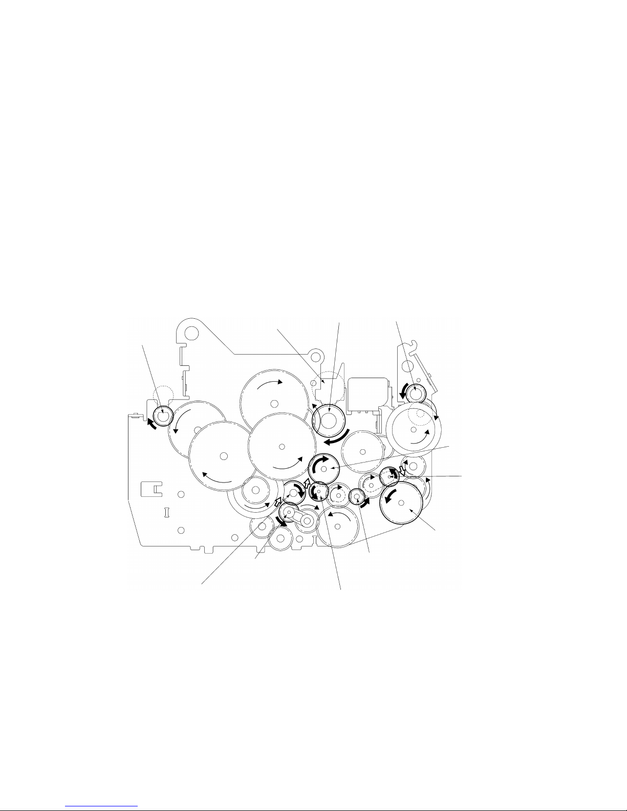
•Operation During Film Compression-Feed
1. When the leading edge of the document enters the compression-feed area, LF
motor starts to rotate counterclockwise, as indicated by the arrow.
2. Planet gear (A), which had been free, moves to engage with drive gear (A). The
drive from the LF motor is then transmitted to the various gears, as shown in the
diagram, and the driving roller rotates as indicated by the arrow. Also, planet
gear (B) moves against the drive gear (B) and planet gear (C) moves against the
drive gear (C), such that the LF motor drive continues to be transmitted to the
paper feed roller and paper eject roller, without changing the direction of roller
rotation.
3. The rotation of the driving roller is transmitted to the sub-roller. These rollers
feed the films and press them against the document. At this time, the rotations
of the paper feed roller and paper eject roller continue uninterrupted.
4. When the trailing edge of the document leaves the compression-feed area and
the X-cutters finish cutting the film, the LF motor reverses to rotate
counterclockwise. Planet gear (A) again becomes free such that the driving
roller rotation stops and feeding of the films also stops.
Paper feed roller
Sub-roller Driving roller Paper eject roller
Drive gear (A)
Drive gear (C)
Planet gear (C)
LF motor gear
Planet gear (A)
Planet gear (B)
Drive gear (B)
Fig. 2.1-3Operation During Film Compression-Feed

2-
4
2.1.3 Cutter Mechanism (Border Mode)
The cutter mechanism cuts the laminated document to the size of the document plus an
added border. Both edges of the films are cut to suit the width of the document and the
leading edge and trailing edge are cut according to the document length.
•Y-Cutter Vertical Drive Operation
1. The TC motor rotates clockwise from its reference position to drive the cam
clockwise via a series of gears. The cam rotates the Y-diversion lever clockwise
about its pivot. (All rotations indicated by arrows. )
When the Y-diversion lever reaches its maximum displacement position with the
cam at approximately its 180°‹ rotated position, rotation of the TC motor pauses.
2. When the Y-diversion lever reaches its maximum displacement position, its
movement lowers the two Y-cutter blades from the standby position to the
cutting position, where they start cutting the edges of the laminated film.
3. When the Y-axis cutters reach the trailing edge cutting position, the TC motor
starts rotating again and stops when it reaches its reference position. This
rotation returns the cam and Y-diversion lever to their original positions and the
cutters move to their standby positions.
Y-cutter blade
Pivot
Standby position
Cutting
position
Planet gear
Film
Film surface
TC motor
Idle gear 1
Idle gear 2
Idle gear 3
Cam (hatched area)
Y-diversion lever
TC motor gear
Fig. 2.1-4Y-Cutter Vertical Drive Operation

2-
5
•Cutting Leading and Trailing Edges (X-cutter Mechanism)
1. All the rollers which feed the document stop when the cut position at the leading
edge of the document reaches the cutting position of the rotary cutter and fixed-
blade cutter.
2. The DC motor rotates to drive the carriage in the X-cutter assembly via the spiral
mechanism (not illustrated).
3. As the carriage makes a reciprocal movement, the rotary cutter attached to the
carriage moves against the fixed cutter to cut the compressed leading edge of
the document.
4. The rotation of the rollers which feed the document restarts when the cutting of
the leading edge is complete. Then, when the cut position at the trailing edge of
the document reaches the cutting position of the rotary cutter and fixed-blade
cutter, the feed rollers stop again.
5. The document trailing edge is cut in the same way as the leading edge, by a
reciprocal movement of the rotary cutter attached to the carriage.
6. The rotation of the rollers restarts to feed the laminated document from the eject
gate after the cutting of the trailing edge is complete.
Rotary cutter Document
Sub-roller
Driving roller
DC motor
Paper eject sub-roller
Paper eject roller
X-cutter
Frame
Section A-A’
DC motor FrameRotary cutter
Carriage
Paper eject roller
Paper eject sub-roller
Fixed cutter
Driving roller
Sub-roller
Document
Fig. 2.1-5Cutting Leading and Trailing Edges (X-cutter Mechanism)

2-
6
2.1.4 Paper Size Detector Mechanism
•Paper Length Detection
1. When the leading edge of the document passes between the paper feed rollers,
it rotates the paper sensor crank about the pivot to turn on the paper sensor
which detects the document leading edge.
2. When the trailing edge of the document passes out of the paper feed rollers, the
paper sensor crank reverts to its original position to turn off the paper sensor to
detect the document trailing edge.
Document feed surface
Paper feed sub-roller
Paper feed roller
Pivot
Paper sensor crank
Paper sensor
ON
OFF
Fig. 2.1-6Paper Length Detection

2-
7
•Paper Width Detection
1. The Y-cutter arm L (sensor unit) moves in the direction of the arrow. When the
PL detect lever touches the document, it rotates about the pivot to switch off the
photosensor.
2. When the photosensor turns off, the Y-cutter arm L movement stops and this
position is detected as the document width.
Y-cutter arm L
Sensor unit
Document
Pivot
Part of the PL detect lever that touches the document.
PL detect lever
Photosensor
* Photosensor ON status
* Photosensor OFF status
Fig. 2.1-7Paper Width Detection

2-
8
2.1.5 Trimming Mechanism
1. When a corner of the laminated document is inserted over the T-cutter plate, the
sensor lever operates a leaf switch that detects the document.
2. When the document is detected, the motor gear of TC motor rotates in the direction
of the arrow (counterclockwise) from its reference position to drive the T-cam gear in
the direction indicated by the arrow (clockwise) via a series of gears.
3. Rotation of the T-cam gear forces the T-cam roller to make a vertical movement,
such that T-lever1 moves vertically, rotating around its pivot.
4. As T-lever 1 moves vertically, the T-cutter mounted on the end of T-lever 1 moves
up and down, trimming the corner of the laminated document into a rounded radius.
T-sensor lever Leaf switch
Laminated
document
Pivot
T-cutter Planet gear
Idle gear 2
Idle gear 3
T-lever 1
T-cam roller
T-cam gearIdle gear 1TC motor Motor gear
T-cutter plate
Fig. 2.1-8Trimming Mechanism

Chapter 3.
DISASSEMBLY PROCEDURES

i
CONTENTS
Chapter 3. DISASSEMBLY PROCEDURES
3.1 Safety Precautions ............................................................................................................3-1
3.2 Removing the Film Cartridge............................................................................................3-1
3.3 Covers...............................................................................................................................3-2
3.3.1 Removing the Trimmer Upper Cover...................................................................3-2
3.3.2 Removing the Top Cover......................................................................................3-3
3.3.3 Removing the Sub-tray.........................................................................................3-4
3.3.4 Removing the Paper Tray and Paper Guide.........................................................3-4
3.3.5 Removing the Body Cover B.................................................................................3-5
3.3.6 Removing the Front Cover....................................................................................3-7
3.3.7 Removing the Cover Switch Assy ........................................................................3-8
3.3.8 Removing the Dial Switch Holder Assy B.............................................................3-9
3.3.9 Disassembling the Dial Switch Holder Assy B ...................................................3-10
3.4 Chassis............................................................................................................................3-12
3.4.1 Removing the Harness Connectors....................................................................3-12
3.4.2 Removing the PE Sensor Unit............................................................................3-12
3.4.3 Removing the Chassis Unit ................................................................................3-13
3.5 PCBs................................................................................................................................3-15
3.5.1 Removing the Main PCB Assy............................................................................3-15
3.5.2 Removing the Jack PCB Assy............................................................................3-15
3.5.3 Removing the Switch PCB Assy.........................................................................3-16
3.6 T-Chassis ........................................................................................................................3-17
3.6.1 Removing the T-Chassis Unit.............................................................................3-17
3.6.2 Disassembling the T-Chassis Unit......................................................................3-18
3.7 Y-CA Chassis..................................................................................................................3-19
3.7.1 Removing the Y-CA Chassis Assy .....................................................................3-19
3.7.2 Disassembling the Y-CA Chassis Assy..............................................................3-20
3.7.3 Removing the Roller Holder Assy.......................................................................3-21
3.7.4 Disassembling the Roller Holder Assy ...............................................................3-22
3.8 Sensor Frame and Y-cutter Arm L..................................................................................3-23
3.8.1 Removing the Sensor Frame..............................................................................3-23
3.8.2 Removing the Y-cutter Arm L .............................................................................3-23
3.8.3 Disassembling the Sensor Frame ......................................................................3-24
3.8.4 Disassembling the Y-cutter Arm L......................................................................3-25
3.9 Paper Feed Roller...........................................................................................................3-26
3.9.1 Removing the Paper Feed Sub-roller Assy........................................................3-26
3.9.2 Removing the Paper Feed Roller Assy...............................................................3-27

ii
3.10 Paper Eject Roller ...........................................................................................................3-28
3.10.1 Removing the Y-D Shaft.....................................................................................3-28
3.10.2 Removing the Paper Eject Sub-roller Unit..........................................................3-29
3.10.3 Removing the Paper Eject Roller Unit................................................................3-29
3.11 Y-diversion Lever ............................................................................................................3-30
3.11.1 Removing the Y-diversion Lever Assy................................................................3-30
3.11.2 Disassembling the Y-diversion Lever Assy ........................................................3-31
3.12 X-cutter............................................................................................................................3-32
3.12.1 Removing the X-cutter Unit.................................................................................3-32
3.12.2 Disassembling the Tape Sensor Unit .................................................................3-32
3.13 Driving Roller...................................................................................................................3-33
3.13.1 Removing the Driving Roller...............................................................................3-33
3.14 Left Side of the Chassis ..................................................................................................3-33
3.14.1 Removing the Gears...........................................................................................3-33
3.14.2 Disassembling the Left Side of the Chassis.......................................................3-35
3.15Right Side of the Chassis................................................................................................3-36
3.15.1 Disassembling the Right Side of the Chassis.....................................................3-36
3.16 Lower Chassis.................................................................................................................3-37
3.16.1 Removing the Left and Right Sides of the Chassis............................................3-37
3.16.2 Removing the Cassette Holder...........................................................................3-38
3.16.3 Removing the Encoder (ENC) Sensor PCB.......................................................3-38
3.16.4 Removing the Cassette Detect Switch...............................................................3-39
This manual suits for next models
2
Table of contents
Other Brother Laminator manuals


