Brother LX-300 User manual

SERVICE MANUAL
MODEL: LX-1200/LX-300

COOL LAMINATOR
SERVICE MANUAL
MODEL: LX-1200/LX-300

Unauthorized copying of all or part of the contents of this manual is prohibited.
The contents of this manual may change without notice.

INTRODUCTION
This Service Manual describes the Cool Laminator LX-1200/LX-300 specifications, operating
principles of the mechanisms, disassembly and reassembly procedures, and maintenance and
troubleshooting procedures.
This Service Manual is intended for use by trained technicians. It is not intended for use by the
user.
The manual is divided into the following chapters.
Chapter 1. Specifications
Chapter 2. Mechanisms
Chapter 3. Disassembly Procedures
Chapter 4. Reassembly Procedures
Chapter 5. Electronic Controllers
Chapter 6. Maintenance
Chapter 7. Troubleshooting
Appendix Main PCB Circuit Diagram

Chapter 1.
SPECIFICATIONS

i
CONTENTS
Chapter 1. SPECIFICATIONS
1.1 Mechanical Specifications.................................................................................................1-1
1.1.1 Appearance...........................................................................................................1-1
1.1.2 Operating Panel....................................................................................................1-2
1.1.3 Indicators...............................................................................................................1-2
1.2 Electrical Specifications....................................................................................................1-2
1.2.1 Power Supply........................................................................................................1-2
1-1
1.1 Mechanical Specifications
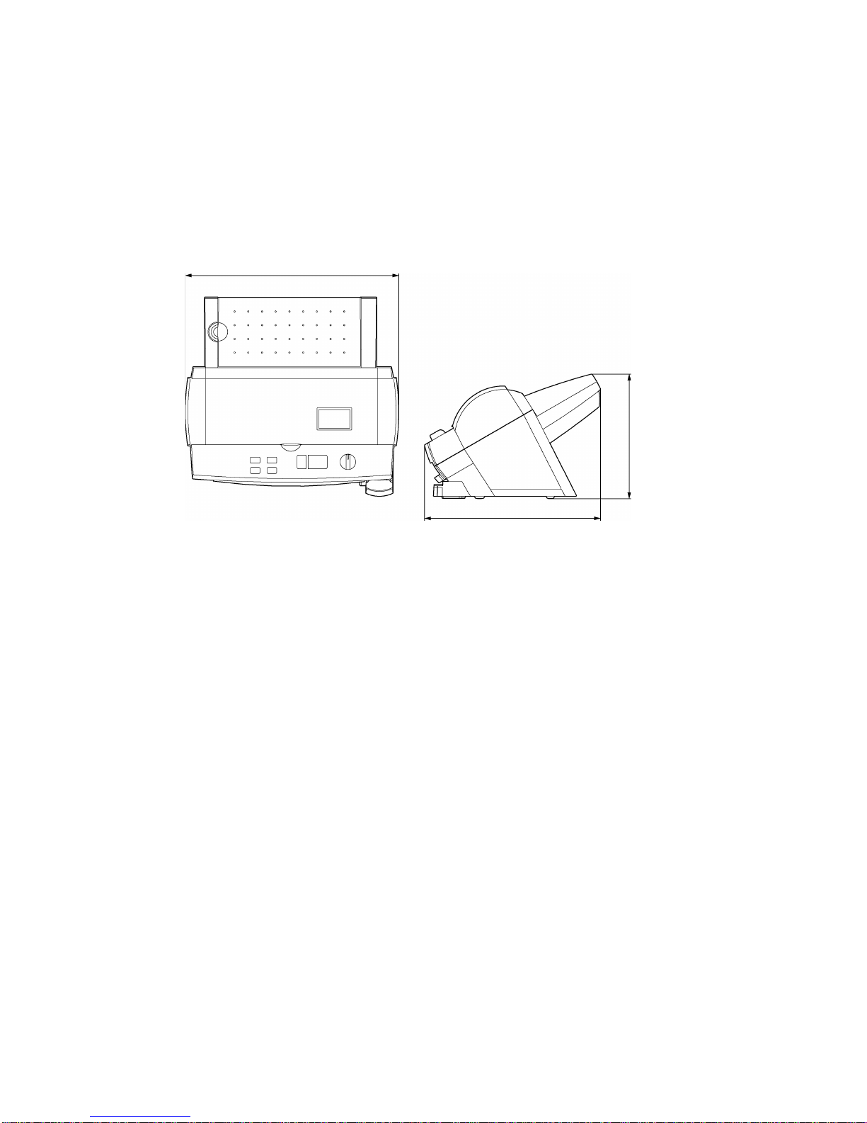
1.1.1 Appearance
[1] External dimensions (W x D x H) 468 mm x 387 mm x 273 mm
[2] Weight Approx. 8.3 kg (main unit only)
468 mm
387 mm
273 mm
Fig. 1.1-1 Appearance
1
-2
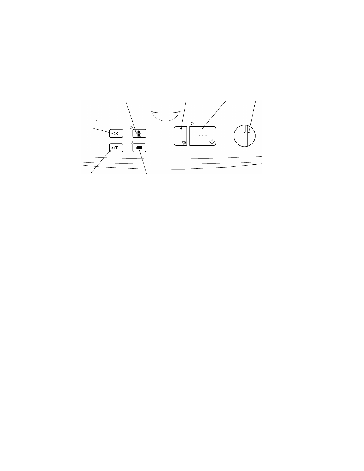
1.1.2 Operating Panel
[1] Number of Keys 7 (Start key, Stop key, Cut key, Feed key,
Extra border key, Continuous key, Cutting mode selector)
[2] Key Arrangement
P
ower switch
C
utting mode selector
C
ontinuous key
Extra border key
Feed key
Cut key
S
tart key
S
top key
Fig. 1.1-2 Key Arrangement
1.1.3 Indicators
[1] Positions Start key LED (green)
Continuous key LED (green)
Extra border key LED (green)
Error LED (red)
1.2 Electrical Specifications
1.2.1 Power Supply
[1] Power supply Commercial power supply (locally available power supply).
Converted to DC by the AC adaptor.

Chapter 2.
MECHANISMS

i
CONTENTS
Chapter 2. MECHANISMS
2.1 Mechanical Operating Principles......................................................................................2-1
2.1.1 Description of Mechanisms (Border Mode)..........................................................2-1
2.1.2 Feed and Compression Mechanisms...................................................................2-2
2.1.3 Cutter Mechanism (Border Mode)........................................................................2-5
2.1.4 Paper Size Detector Mechanism..........................................................................2-7
2.1.5 Trimming Mechanism ...........................................................................................2-9

2-1
2.1 Mechanical Operating Principles
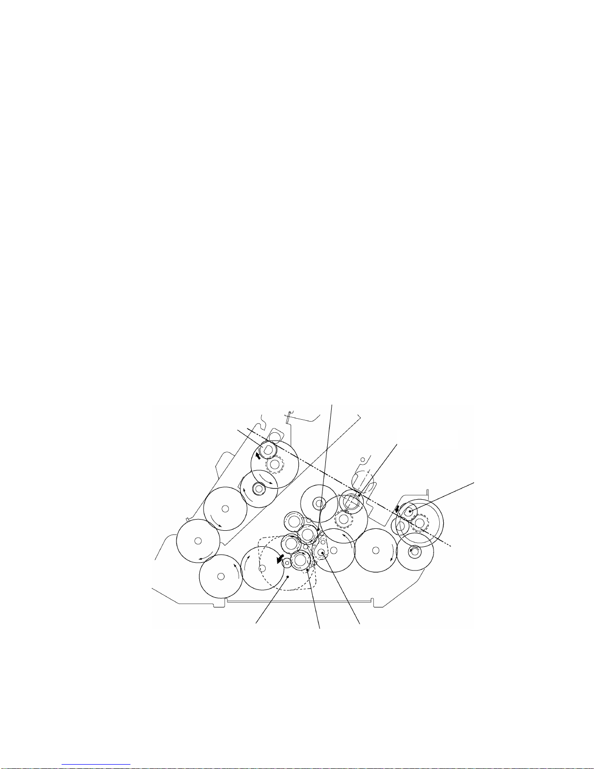
2.1.1 Description of Mechanisms (Border Mode)
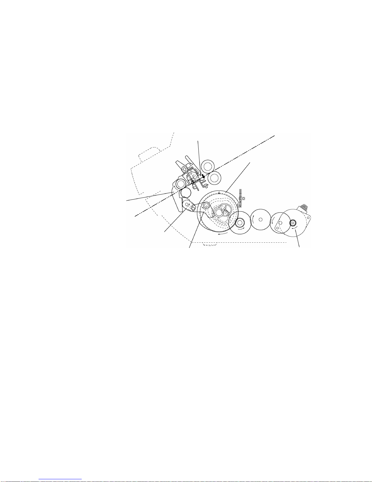
1. When a document is inserted into the paper loading gate, the paper feed rollers feed
it to the driving roller.
2. As the document passes between the paper feed rollers, the paper size detector
determines its size (length and width).
3. When the document passes between the film cartridges it is sandwiched between
the upper and lower films in the compression-feed area, where the films and
document are compressed between the driving roller and sub-roller.
4. The compressed document and film is fed to the cutting area, where it is cut to the
document size detected by the paper size detector with borders added. It is then
transported to the next stage.
5. The laminated document is fed out of the eject gate by the paper eject rollers.
E
ject gate
Y-cutter blade
Paper eject roller
X-cutter unit
Paper eject sub-roller
Ejecting area
Sub-roller
Film cartridge
C
utting area
D
riving roller
Compression-feed area
R
oll film (lower)
Paper feed roller
Paper loading area
Paper length detector
P
aper loading gate
P
aper width detector
P
aper feed
s
ub-roller
R
oll film (upper)
Fig. 2.1-1 Description of Mechanisms
2
-2
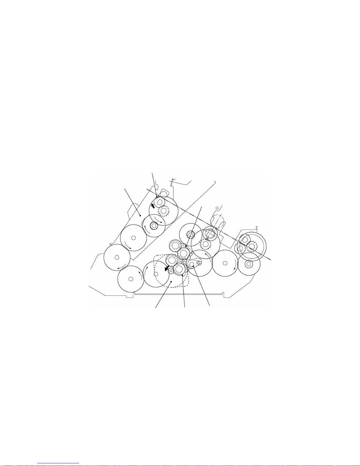
2.1.2 Feed and Compression Mechanisms
The feed and compression mechanism controls the motor drive to feed the document
into the film cartridge, compression-feed the films, and eject the laminated document.
The operation is basically divided into three separate operations: feeding a document
into the Film cartridge, compression-feeding the films, and ejecting the laminated
document.
Normal Mode
When documents are laminated one at a time (that is, not in the Continuous mode), the
lamination operation comprises the operations A and B below.
S
A. Feeding document into Film cartridge and ejecting the laminated document
1. The SG motor mounted at the right of the chassis runs to rotate the Control cam
gear (also mounted at the right of the chassis) to its prescribed position.
2. As the Control cam gear rotates, the LF change shaft is rotated to its prescribed
position by the cam on the Control cam gear.
3. A cam is mounted on the LF motor end of the LF change shaft (at the left of the
chassis). As the LF change shaft rotates, this cam rotates the two Gear holders
at the left of the chassis, which transmit the LF motor drive as shown in the
diagram.
4. As a result of steps 1 to 3 above, the drive is transmitted to the Paper feed roller
and Paper eject roller. The document is fed into the Film cartridge by the Paper
feed roller as the LF motor rotates. After the trailing edge has been cut by the X
cutter, the laminated document is ejected by the Paper eject roller.
G
ear holder
Paper feed roller
L
F change shaft
Paper eject roller
G
ear holder
LF motor
D
riving roller
Fig. 2.1-2 Operation when Feeding Document into the Film Cartridge or when Ejecting a Laminated Document

2
-3
S
B. Compression-feeding the films
1. The SG motor mounted at the right of the chassis runs to rotate the Control cam
gear (also mounted at the right of the chassis) to its prescribed position.
2. As the Control cam gear rotates, the LF change shaft is rotated to its prescribed
position by the cam on the Control cam gear.
3. A cam is mounted on the LF motor end of the LF change shaft (at the left of the
chassis). As the LF change shaft rotates, this cam rotates the two Gear holders
at the left of the chassis, which transmit the LF motor drive as shown in the
diagram.
4. As a result of steps 1 to 3 above, the drive is transmitted to the Driving roller that
compresses the films. During this operation, the Paper feed roller and Paper
eject roller rotate continuously to feed in documents and eject laminated
documents.
G
ear holder
Driving roller
Paper eject roller
L
F change shaft
G
ear holder
LF motor
Paper feed holder
Paper feed roller
Fig. 2.1-3 Operation during Film Compression-Feed
2
-4
Continuous Mode
When the second or subsequent document are inserted in the Continuous mode, the
operation C described below feeds the documents to the prescribed position.
S
C. Feeding Document Only into Film Cartridge
1. The SG motor mounted at the right of the chassis runs to rotate the Control cam
gear (also mounted at the right of the chassis) to its prescribed position.
2. As the Control cam gear rotates, the LF change shaft is rotated to its prescribed
position by the cam on the Control cam gear.
3. A cam is mounted on the LF motor end of the LF change shaft (at the left of the
chassis). As the LF change shaft rotates, this cam rotates the two Gear holders at
the left of the chassis, which transmit the LF motor drive as shown in the diagram.
4. As a result of steps 1 to 3 above, the drive is transmitted to the Paper feed roller
only. A document is fed into the Film cartridge by the Paper feed roller as the LF
motor rotates.
G
ear holder
L
F change shaft
P
aper feed roller
Paper feed holder
LF motor
G
ear holder
Fig. 2.1-4 Operation when Feeding Document into the Film Cartridge in the Continuous Mode
2
-5
2.1.3 Cutter Mechanism (Border Mode)
The cutter mechanism cuts the laminated document to the size of the document plus an
added border. Both edges of the films are cut to suit the width of the document and the
leading edge and trailing edge are cut according to the document length.
S
Y-Cutter Vertical Drive Operation
The SG motor drive rotates the Control cam gear to its prescribed position. This
rotation is transmitted via the YC lift arm and YC lift shaft to rotate the Y-diversion
lever and set the Y cutter to the cutting position.
C
ontrol cam gear
Y
C lift arm
Y-diversion lever
SG motor
YC lift shaft
Y
-cutter blade
Fig. 2.1-5 Y-Cutter Vertical Drive Operation
2
-6
S
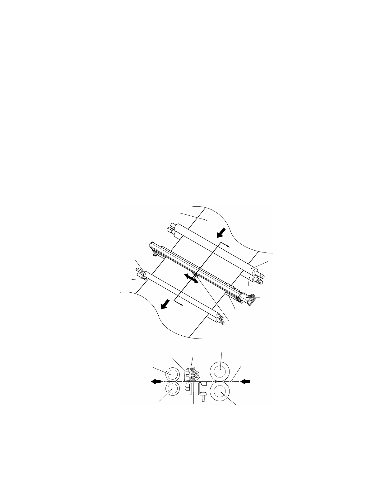
Cutting Leading and Trailing Edges (X-cutter Mechanism)
1. All the rollers which feed the document stop when the cut position at the leading
edge of the document reaches the cutting position of the rotary cutter and fixed-
blade cutter.
2. The DC motor rotates to drive the carriage in the X-cutter assy via the spiral
mechanism (not illustrated).
3. As the carriage makes a reciprocal movement, the rotary cutter attached to the
carriage moves against the fixed cutter to cut the compressed leading edge of
the document.
4. The rotation of the rollers which feed the document restarts when the cutting of
the leading edge is complete. Then, when the cut position at the trailing edge of
the document reaches the cutting position of the rotary cutter and fixed-blade
cutter, the feed rollers stop again.
5. The document trailing edge is cut in the same way as the leading edge by a
reciprocal movement of the rotary cutter attached to the carriage.
6. The rotation of the Paper eject roller and Paper feed roller restarts to feed the
laminated document from the eject gate after the cutting of the trailing edge is
complete. (In this timing, the driving roller does not rotate.)
Sub-roller
D
riving roller
F
ixed cutter
R
otary cutter
D
ocument
D
riving roller
S
ub-roller
Carriage
Document
Paper eject roller
Paper eject sub-roller
R
otary cutter
Carriage
Paper eject roller
Paper eject sub-roller
S
ection A-A'
A
A
'
F
ixed cutter
Fig. 2.1-6 Cutting Leading and Trailing Edges (X-cutter Mechanism)
2
-7
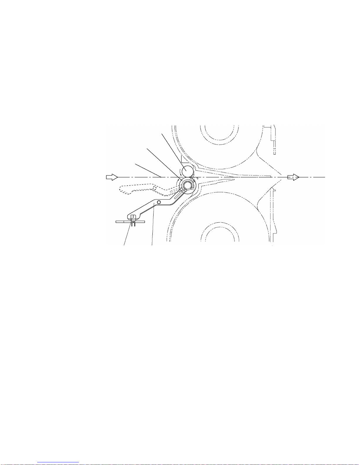
2.1.4 Paper Size Detector Mechanism
S
Paper Length Detection
1. When the leading edge of the document passes between the Paper feed rollers,
the Actuator top operates about the pivot to turn on the Paper sensor and detect
the document leading edge.
2. When the trailing edge of the document passes out of the Paper feed rollers, the
Actuator top reverts to its original position to turn off the Paper sensor and
detect the document trailing edge.
Paper feed sub-roller
Paper feed roller
Actuator top
Document feed surface
Paper sensor
Fig. 2.1-7 Paper Length Detection
2
-8
S
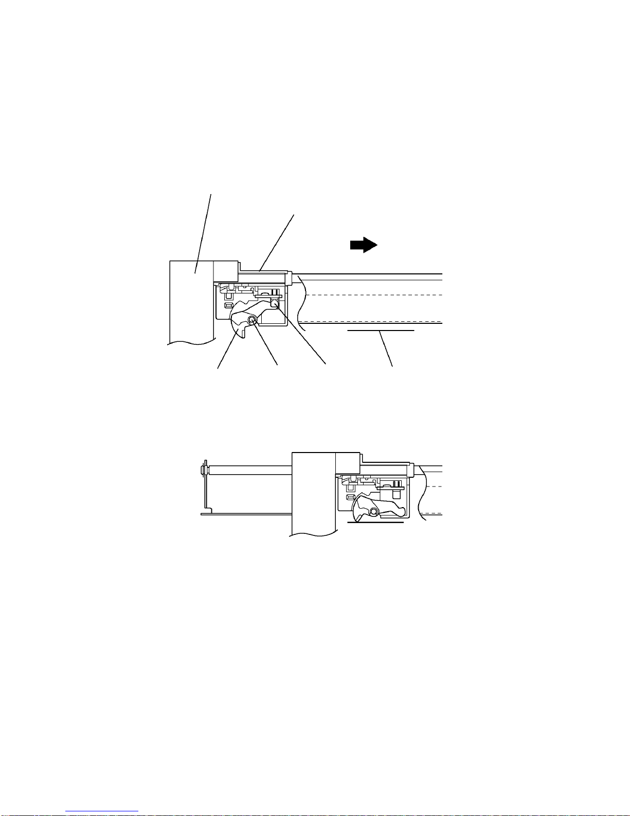
Paper Width Detection (Y-CA sensor)
1. As the Y-cutter arm (Y-CA sensor carriage) moves in the direction of the arrow,
the document contacts the Actuator Y, which rotates about the pivot to switch off
the Y-CA sensor (photosensor).
2. When the Y-CA sensor turns off, the Y-cutter arm movement stops and this
position is detected as the document width.
Y
sensor carriage
Y
-CA sensor
Y
-cutter arm
D
ocument
Pivot
Actuator Y
∗Photosensor OFF status
∗Photosensor ON status
Fig. 2.1-8 Paper Width Detection
2
-9
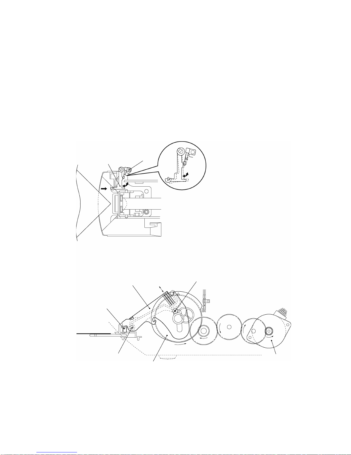
2.1.5 Trimming Mechanism
1. When a corner of the laminated document is inserted over the T-cutter plate, the T-
sensor lever operates a leaf switch (TRI) that detects the document.
2. When the document is detected, the motor gear of the SG Motor rotates from its
reference position to the prescribed position to rotate the Control cam gear in the
direction of the arrow (counterclockwise) via a series of gears.
3. Rotation of the Control cam gear forces the T-cam roller to move vertically, such
that T-lever also moves vertically, rotating around its pivot.
4. As T-lever moves vertically, the T-cutter assy mounted on the end of T-lever moves
up and down, trimming the corner of the laminated document into a rounded radius.
T
-cam roller
Leaf switch
T-sensor lever
T
-lever
T-cutter unit
Pivot
Control cam gear
SG motor
Fig. 2.1-9 Trimming Mechanism

Chapter 3.
DISASSEMBLY PROCEDURES
This manual suits for next models
1
Table of contents
Other Brother Laminator manuals


