Brouwland 057.110 Series User manual

Wort Cooler Plate Heat Exchanger, Stainless Steel
Specifications
057.110.500
057.110.1000
057.110.2000
Number of plates
21
27
37
Construction
Fully stainless steel AISI
316
Fully stainless steel AISI
316
Fully stainless steel AISI
316
Gaskets
Nitrile
Nitrile
Nitrile
Capacity
500 l wort per hour
Cooling from 95°C to 20°C
with 1 m³ cooling water at
10°C
1,000 l wort per hour
Cooling from 95°C to 20°C
with 2 m³ cooling water at
10°C
2,000 l wort per hour
Cooling from 95°C to 20°C
with 4 m³ cooling water at
10°C
Cooler surface area
(m²)
0.882
1.134
1.554
Dimensions
(HxWxD)
65 x 18 x 40 cm
65 x 18 x 40 cm
65 x 18 x 40 cm
Wort port
NW32 tube and DIN32
connector
NW32 tube and DIN32
connector
NW32 tube and DIN32
connector
Water port
1" male gas thread
1" male gas thread
1" male gas thread
Construction and Operation
Construction
The plate heat exchanger consists of a set of profiled flow plates fitted with rubber gaskets. The plates
are fitted in the structure and clamped together by a set of tie rods. The capacity of the heat
exchanger depends on the number of plates (Figure 1).
Plate stack
The plates have glued-on gaskets. The gaskets provide sealing between the media and the atmosphere
when the plates are clamped together.
Double gaskets with intermediate drain areas are fitted at two corners of the plates. The plates are
assembled with half of the plates rotated 180° so that the drain areas are located alternately on the
left and right sides. In this way the plate stack forms a system with parallel intermediate spaces and
media flow in opposite directions in alternating intermediate spaces (Figure 2).
Intermediate frames
If the plate heat exchanger operates with different media at the same time, it may be necessary to fit
intermediate frames. The intermediate frames divide the plate heat exchanger into several sections.
The intermediate frames have corner elements that provide the connection between the different
sections and/or the pipe ports. Two ports can be present in the same corner element, each connected
to its own section of the heat exchanger. See the schematic flow diagram.
Brouwland
Korspelsesteenweg 86 • B-3581 Beverlo, Belgium
Phone +32 (0)11 40 14 08 • Fax +32 (0)11 34 73 59
sales@brouwland.com • www.brouwland.com
Manual
057.110.x Wort Cooler Plate Heat Exchanger,
Stainless Steel
1 / 11

Figure 1
Figure 2
Plate structure
Corner punching
Holes are punched in the corners of the plates as shown in the drawings (see Figure 4). The media flow
in the plate heat exchanger is shown in similar drawings. The punched corner holes are identified by a
code.
For example, the code "1234" means that all four corners of the plate have punched holes, while the
code "0204" means that corners 2 and 4 have punched holes and corners 1 and 3 do not.
Identification code
The plates are designed to be used facing either left or right by simply rotating the plate by 180°.
Regardless of the actual orientation of the plates (left or right facing), the hole code (see Figure 3)
always starts with hole 1 in the top left corner as seen from the gasket side.
Replacing plates
Plates can be replaced or new plates fitted after the tie rods have been loosened and removed. Before
fitting replacement plates, check that the new plates match the ones to be replaced.
The number of plates can be reduced. However, you should bear in mind that plates must be removed
in pairs so that the plate stack still consists of an assembly of alternating left- and right-facing plates
after the plates have been removed. The plates that are removed must have holes punched in all four
corners. If the number of plates is reduced, the clamping hardware must be adjusted to correspond to
the remaining number of plates.
Brouwland
Korspelsesteenweg 86 • B-3581 Beverlo, Belgium
Phone +32 (0)11 40 14 08 • Fax +32 (0)11 34 73 59
sales@brouwland.com • www.brouwland.com
Support
beams
Stress beams
Plate stack
Fixed
cover
Moveable cover
Column
Tie rod / plug
A
B
Manual
057.110.x Wort Cooler Plate Heat Exchanger,
Stainless Steel
2 / 11

Caution: Reducing the plate count means that some of the plates are removed, resulting in a smaller
heat transfer area. This reduction also causes the pressure drop over the plate heat exchanger to rise.
Schematic drawings
This guide includes two drawings that depict the supplied plate heat exchanger (a schematic drawing
and a diagram).
Schematic drawing
The schematic drawing shows the dimensions of the plate heat exchanger –i.e. the width, length and
ports (Figure 5).
Brouwland
Korspelsesteenweg 86 • B-3581 Beverlo, Belgium
Phone +32 (0)11 40 14 08 • Fax +32 (0)11 34 73 59
sales@brouwland.com • www.brouwland.com
Manual
057.110.x Wort Cooler Plate Heat Exchanger,
Stainless Steel
3 / 11

Diagram (Figure 6)
The diagram contains the following information:
Plate punching codes
Number of plates
Port locations
Number of intermediate frames and their positions
Gasket specifications
Schematic flow diagram
The diagram shows a side view of the plate heat exchanger, the plate assembly and the media flow
through the plate stack. There are four continuous horizontal lines on the diagram that mark the four
corner holes of the plates.
The left-facing plates are indicated by long vertical lines. The right-facing plates are indicated by short
vertical lines.
Figure 7
Brouwland
Korspelsesteenweg 86 • B-3581 Beverlo, Belgium
Phone +32 (0)11 40 14 08 • Fax +32 (0)11 34 73 59
sales@brouwland.com • www.brouwland.com
M12V
Manual
057.110.x Wort Cooler Plate Heat Exchanger,
Stainless Steel
4 / 11

Port locations
F = fixed cover
B = moveable cover
M = intermediate frame
H = horizontal
V = vertical
Example:
The paired ports are shown on the symmetrical drawings (Figure 7). The intermediate frames are
shown with dashed lines and are applicable to the extent that they are included in the plate heat
exchanger. The ports are marked by alphanumeric codes.
Gasket structure
New gaskets
The first plate after the fixed cover and after an intermediate frame
must be fitted with a gasket that fills the entire gasket groove. This
gasket is trimmed from a standard gasket. Accordingly, you should
check how the existing gaskets are trimmed before removing them
(see Figure 9).
Non-adhesive or adhesive gaskets
Some plate heat exchangers are supplied with non-adhesive
Sonder Snap gaskets. This allows the gaskets to be replaced
without using adhesive. The gasket of the first plate after the fixed
cover and the first plate after an intermediate frame must be an
adhesive type (see Figure 9). Remove all gasket residues before
fitting a new gasket. Please take the following information into
account for plate heat exchangers with adhesive gaskets.
Adhesive
Pliobond 25 / Scotchgrip 847 is a solvent-based nitrile rubber
adhesive (25% solids). This adhesive is semi-thermoplastic, which
means that old gaskets can be loosened with hot water.
Degreaser
Use acetone to clean and degrease new gaskets and gasket grooves. Ensure that the degreaser has
completely evaporated before applying the adhesive.
Caution: Inhaling solvents is harmful to health.
Brouwland
Korspelsesteenweg 86 • B-3581 Beverlo, Belgium
Phone +32 (0)11 40 14 08 • Fax +32 (0)11 34 73 59
sales@brouwland.com • www.brouwland.com
Vertical support point
Intermediate frame
Intermediate frame of the fixed cover
Corner hole number
Manual
057.110.x Wort Cooler Plate Heat Exchanger,
Stainless Steel
5 / 11

Applying adhesive
Adhesive can be applied after the gaskets and gasket grooves have been cleaned using a cloth
moistened with a cleaning product. The adhesive surfaces must be completely clean, with no
fingerprints or the like. Use a brush to apply a thin film of prepared adhesive to the adhesive surfaces
of the gaskets. Then set the gaskets aside on a clean, dry surface. Apply a thin film of adhesive to the
gasket grooves of the plates and then press the gaskets into the grooves with equal pressure.
When applying adhesive to the plates, start with the corners and then do the straight edges. Adhesive
application is best performed on a sturdy table. Stack the plates after all the gaskets have been fitted
in the gasket grooves.
After the gaskets have been glued, re-assemble the plates in the stack and clamp the heat exchanger
together again. See the "Dismantling and clamping" section. The plate heat exchanger may be heated
with hot water to reduce the adhesive curing time. However, no pressure should be applied to the
water.
Curing time:
approx. 2 hours at 80 –100°C (194 –212°F)
approx. 24 hours at 40 –50°C (104°F)
approx. 48 hours at room temperature
If it is not possible to warm the heat exchanger, it should be kept as warm as possible with the
connections fitted and started up cautiously.
Heat exchanger fitting
There are two important aspects that must be kept in mind when fitting a heat exchanger:
the required space
the piping
Required space
Provide enough space so that the plate heat exchanger
can easily be dismantled for servicing and in the event
of any upgrades (Figure 10).
It must be possible to remove and replace the plates
and tie rods without any problems. It must be possible
to pull the moveable cover fully to the rear to provide
sufficient space for removing and fitting the plates
(Figure 11).
Brouwland
Korspelsesteenweg 86 • B-3581 Beverlo, Belgium
Phone +32 (0)11 40 14 08 • Fax +32 (0)11 34 73 59
sales@brouwland.com • www.brouwland.com
Manual
057.110.x Wort Cooler Plate Heat Exchanger,
Stainless Steel
6 / 11

Piping
The piping must be installed according to the
accompanying diagram to allow the plate heat
exchanger to achieve its specified capacity. When
fitting the piping, bear in mind that it must be possible
to remove any rubber sleeves in the fixed cover. The
piping must always be fitted on pipe supports so that
the plate heat exchanger is not under mechanical
stress. The piping must be sufficiently flexible to allow
for the thermal expansion of the plate heat exchanger.
Initial use and operating instructions
The following aspects must be respected when putting a plate heat exchanger into service and using
the heat exchanger:
Operating pressure
Pump starting
Pressure surges and vibration
Leakage at start-up
Air bleeding
Pressure rise and temperature changes
Leakage during operation
Prolonged out-of-service time
Operating pressure
A nameplate is fitted on the fixed cover of the plate heat exchanger. The maximum operating pressure
is shown on the nameplate. This operating pressure may not be exceeded.
Air bleeding
Air in the plate heat exchanger reduces the heat transfer and increases the pressure drop.
For this reason, it must be possible to bleed air from the heat exchanger.
Pressure rises and temperature changes
The pressure and temperature must be checked regularly during operation. Rising pressure drop and
reduced heat transfer are signs of the formation of deposits on the plates. These deposits must be
removed. See pages 8 and 9 for information about cleaning the plate heat exchanger.
Pump starting
The pump should always be started with the valves closed. Then the valves should be opened slowly to
avoid pressure surges or liquid surges.
Pressure surges and vibration
Positive-displacement pumps and similar devices should not be allowed to transmit pressure surges or
vibrations to the plate heat exchanger. Otherwise metal fatigue may occur in the plates.
Brouwland
Korspelsesteenweg 86 • B-3581 Beverlo, Belgium
Phone +32 (0)11 40 14 08 • Fax +32 (0)11 34 73 59
sales@brouwland.com • www.brouwland.com
Manual
057.110.x Wort Cooler Plate Heat Exchanger,
Stainless Steel
7 / 11

Leakage during operation
See "Troubleshooting" on page 10.
Prolonged out-of-service time
A plate heat exchanger that has been out of service for a prolonged period must be drained and
cleaned. After draining and cleaning, clamp the plate heat exchanger together with light pressure and
cover the plate stack with black plastic to protect the rubber gaskets against exposure to light. Before
the plate heat exchanger is put into service again, it must be reclamped to the indicated minimum
value. See "Assembly and clamping" on page 8.
Leakage at start-up
Leaks may occur when the heat exchanger is put into service. They should stop as soon as the gaskets
and plates reach the operating temperature and the pressure is evenly distributed over the entire plate
heat exchanger.
Disassembly and assembly
Bear the following points in mind when taking apart or fitting the plate heat exchanger:
Relieve pressure and allow unit to cool down
Correct assembly and clamping
Correct dismantling
Relieve pressure and allow unit to cool down
Before the plate heat exchanger is dismantled, the pressure must be relieved and the unit must be
allowed to cool down to a temperature below 35°C. If the plate heat exchanger is dismantled at a
temperature above 35°C, the gaskets may be detached from the plates.
Correct assembly and clamping
Inspect the plates and gaskets carefully before
assembly. The plates must be entirely free from
deposits, and the sealing surfaces must be free
from grease and other contaminants. A grain of
sand on the sealing surface can cause a leak
during operation and damage the gaskets.
Assemble the plates as shown in the diagram
with the gaskets always facing the fixed cover.
If the gaskets are new, clamp the plate heat
exchanger to the minimum value plus 0.1 mm
per plate; otherwise clamp it to the minimum
value. The fixed and moveable covers must be
parallel to each other. For this reason the
clamped assembly must be measured at both
the top and the bottom on both sides.
Brouwland
Korspelsesteenweg 86 • B-3581 Beverlo, Belgium
Phone +32 (0)11 40 14 08 • Fax +32 (0)11 34 73 59
sales@brouwland.com • www.brouwland.com
Manual
057.110.x Wort Cooler Plate Heat Exchanger,
Stainless Steel
8 / 11

Correct dismantling
Loosen the tie rods evenly when dismantling the plate heat exchanger. Remove the moveable cover by
pulling it straight away from the fixed cover. The maximum permissible difference from one side to the
other is just 25 mm. The final part of the dismantling process can be performed on two tie rods fitted
in the middle.
Cleaning
The capacity and the corrosion resistance of the plate heat exchanger depend on the plate stack being
in good condition.
Manual cleaning
Chemical cleaning
Solvents
Inspection of cleaning
Solvents
A suitable solvent can be described as "a product that cleans the plate heat exchanger without
damaging the plates or the gaskets".
Stainless steel has a passivated (protective) film. This film must remain intact, since it is what provides
corrosion resistance.
Manual cleaning
Dismantle the plate heat exchanger and slide the plates apart. Use a soft brush and a suitable solvent
to clean the plates. If a thick layer of limescale or a thick deposit of organic material has formed on the
plates, place the plates in a tub or basin with a suitable solvent. Never use a steel wire brush,
sandpaper or metallic scrapers, as otherwise the plates and the gaskets may be damaged. If
necessary, a high-pressure cleaner may be used. If you use a high-pressure cleaner, be extremely
careful and do not use any abrasives.
Suitable solvents
Organic and greasy deposits can be removed by sodium hydroxide (NaOH) with a maximum
concentration of approximately 1.5% and a maximum temperature of 85°C. Mixing ratio for a 1.5%
solution: 5 parts 30% NaOH to 100 parts of water.
Limescale and mineral deposits can be removed by nitric acid (HNO3) with a maximum concentration of
1.5% and a maximum temperature of 65°C. Mixing ratio for a 1.5% solution: 2.4 parts of 62% HNO3
to 100 parts of water.
Chemical cleaning
Cleaning with chemical products is only possible if the deposits can be dissolved by chemicals. It goes
without saying that only solvents that do not damage any of the materials in the circulation system
may be used. Cleaning without circulation is also possible. This is done by filling the plate heat
exchanger with a suitable solvent. After the product has been allowed to sit in the plate heat
exchanger for a while, it is rinsed out with clean water.
An example of chemical cleaning:
Brouwland
Korspelsesteenweg 86 • B-3581 Beverlo, Belgium
Phone +32 (0)11 40 14 08 • Fax +32 (0)11 34 73 59
sales@brouwland.com • www.brouwland.com
Manual
057.110.x Wort Cooler Plate Heat Exchanger,
Stainless Steel
9 / 11

- Remove product residues and the cooling or heating media
- Rinse with cold or lukewarm water
- Allow a solution of the solvent to circulate through the system
- Rinse with clean hot water
- Rinse again with hot water with a decalcifier additive
- Rinse again with cold or lukewarm water
Inspection of cleaning
Cleaning is very important for the effectiveness of the plate heat exchanger. For this reason, the
cleaning of the plate heat exchanger must be checked, especially in the initial use period. People often
have little experience with the circulation time, temperatures and concentrations of the products that
are used.
Common causes of inadequate cleaning are:
- circulation volume too low
- cleaning period too short
- insufficient amount of chemicals for the deposits on the plates
- operating intervals twice as long
Troubleshooting
Loss of capacity
Internal leaks
External leaks
Loss of capacity
If the heat transfer capacity falls and/or the pressure drop rises, the plate heat exchanger must be
dismantled and the plates must be cleaned (see page 8). The plates must be clamped together
according to the values stated on the nameplate.
External leaks
- The plate heat exchanger may be operating at a higher pressure than the specified operating
pressure. Check the pressure. If it is too high, it must be reduced immediately to the operating
pressure stated on the nameplate.
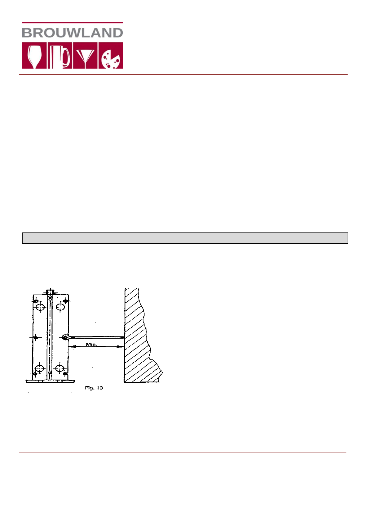
- Adjust the clamping of the plate heat exchanger when it is no longer under pressure. Never exceed
the indicated minimum value when adjusting the clamping.
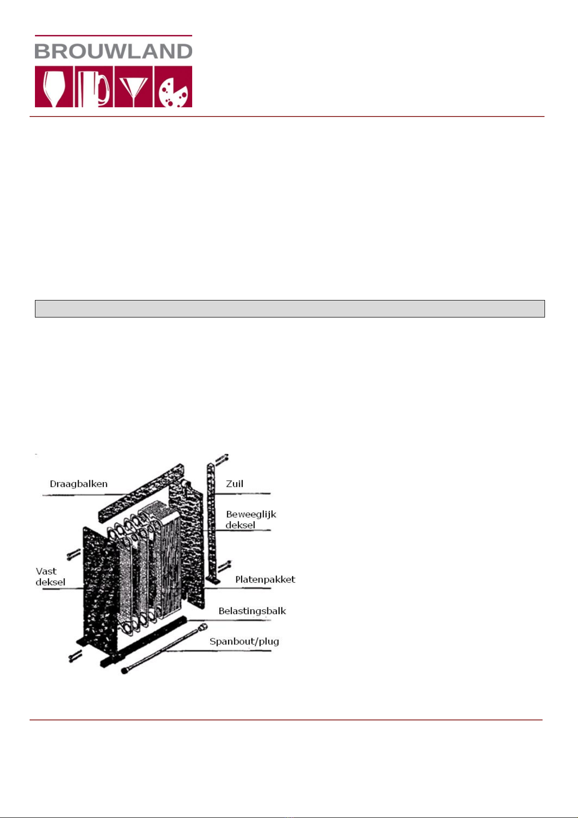
The fixed and moveable covers must always be parallel to each other after the plates have been
clamped together.
- Dismantle the plate heat exchanger for visual inspection. Check whether deposits have formed on the
plates, and check the plates for deformation. Check the gaskets. They must be elastic and not
deformed, and the sealing surfaces must be clean. Carefully clean all plates and gaskets –just one
grain of sand on a sealing surface can cause a leak.
- A plate stack that has been clamped to the minimum value after cleaning should be free from leaks.
If any leaks are present, the gaskets must be replaced.
- If there is a leak from the gasket drain holes, the sealing of the drain area is defective or the plate is
corroded in the drain area.
Internal leaks
If the media get mixed together, you should look for the cause in the holes of one or more plates. The
only way to eliminate the leak is to replace the plate or plates concerned.
Brouwland
Korspelsesteenweg 86 • B-3581 Beverlo, Belgium
Phone +32 (0)11 40 14 08 • Fax +32 (0)11 34 73 59
sales@brouwland.com • www.brouwland.com
Manual
057.110.x Wort Cooler Plate Heat Exchanger,
Stainless Steel
10 / 11

If you suspect a leak, you can use the following procedure to track it down:
- Disconnect a pipe from one of the lower pipe ports. Then apply pressure on the opposite side.
Media should stop flowing out of the disconnected pipe port after the pressure has stabilised. If media
continues to flow out of the pipe port, there is a leak in one or more plates.
Dismantle the plate stack and carefully check each plate. Using a special fluid, check the plates for
cracks.
- Dismantle the plate heat exchanger and allow all the plates to dry. Once the plates are completely
dry, fit them in the heat exchanger and clamp them together. Now the media is circulating at full
power, but only on one side of the plates (every second intermediate space). The other half of the
spaces between the plates is not under pressure and does not receive any fluid.
Stop the circulation after several minutes and carefully dismantle the plate heat exchanger, so that the
dry sides of the plates are not splashed with water. Now carefully examine the plates and look for any
moist spots on the sides of the plates that are otherwise dry. These spots must be carefully checked
for cracks using a special fluid.
- Take the plate heat exchanger apart and check all plates for cracks with a special fluid.
Conversion
The plate heat exchanger has a modular structure, so it can easily be made larger or smaller. This
means that it is easy to change the capacity of the heat exchanger by adding or removing plates.
BROUWLAND BVBA maintains a database of all delivered plate heat exchangers.
We would be pleased to advise you on the conversion of existing plate heat exchangers.
For this purpose, BROUWLAND BVBA only needs to know the serial number on the nameplate.
In response, BROUWLAND BVBA will provide a full description of the conversion procedure and the parts
necessary for the conversion. The conversation data will then be added to the database to keep it up to
date.
Spare parts
When ordering spare parts, please provide the type designation and serial number of the plate heat
exchanger (shown on the nameplate on the fixed cover). This data is necessary to avoid supplying
incorrect parts.
- When ordering plates, always state the correct punching code and indicate whether the plate is left-
facing or right-facing (see the section about plates).
- When ordering a complete set of gaskets and the accompanying adhesive or when ordering solvents,
it is sufficient to state the serial number and the drawing number.
If you order individual gaskets, it is important to state the right type. The gasket types and colour
codes are shown on the diagram.
If you wish to order tie rods, first measure the existing tie rods to ensure that the new tie rods have
the right length.
When contacting BROUWLAND BVBA with regard to your plate heat exchanger, please state the type
designation and serial number shown on the nameplate.
Brouwland
Korspelsesteenweg 86 • B-3581 Beverlo, Belgium
Phone +32 (0)11 40 14 08 • Fax +32 (0)11 34 73 59
sales@brouwland.com • www.brouwland.com
11 / 11
User Guide
057.110.x Wort Cooler Plate Heat Exchanger,
Stainless Steel
This manual suits for next models
3
Table of contents