BROWN Firefly User manual

Brown Manufacturing Group, Inc.
4661 Stafford Ave. S.W.
Wyoming, MI 49548
Phone: 616-249-0200
Fax: 616-249-3211
www.brownmfg.net
User’s Manual
Revision 6
0

Brown Manufacturing Group, Inc.
4661 Stafford Ave. S.W.
Wyoming, MI 49548
Phone: 616-249-0200
Fax: 616-249-3211
www.brownmfg.net
Setup Guide
Revision 6

BrownDigital FireFly set-up guide
Assembly
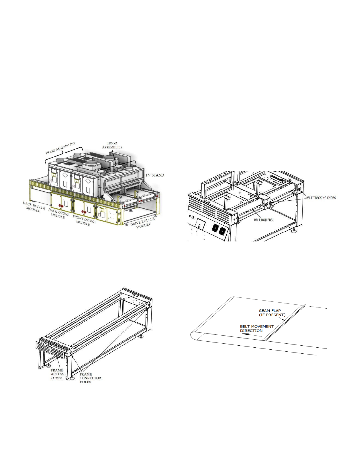
A Firefly dryer consists of several modular assemblies
which are joined together to create a complete conveyor
dryer unit. Common modules are:
Figure 1: DRIVE ROLLER MODULE
Figure 2: FRONT DRONE HEAT MODULE
Figure 3: BACK DRONE HEAT MODULE
Figure 4: BACK ROLLER MODULE
Figure 5: HOOD ASSEMBLY
Figure 6: TV STAND
1

BrownDigital FireFly set-up guide
Assembly Step 1: Ensure Adequate Clearance
Before placing the Firefly modules, it is important to
ensure adequate clearance will be available for both the
main footprint of the machine and maintenance access.
Since the Firefly Curing System is a modular system, the
main footprint of the machine depends on the exact
configuration you purchased. Consult your salesperson
for an engineering drawing of your particular system.
Clearance is required around the heat modules in order
to open control panel doors, pull out filters, and clean
camera boxes. See Figure 7 for specific clearance
numbers.
Figure 7: GENERAL CLEARANCES
Clearance is also required for the heat modules to slide
on their tracks for maintenance access to the center of
the machine. Ensure that nothing blocks the movement
of the heat sections front/back as shown in Figure 8.
Figure 8: ACCESSING CENTER OF SYSTEM
2

BrownDigital FireFly set-up guide
Assembly Step 2: Identify and Arrange
Using the figures in this manual, identify the modules
that shipped with your dryer. Arrange the modules in the
location you wish to install the machine in the correct
orientations for your system. Below is a standard
configuration for a 2 heat section system. As the Firefly
system is a modular system, your configuration may be
different. Consult with Brown Manufacturing for the
exact layout of your system.
Use the leveling legs on each module to bring all the
sections to the same height and level. Shift the modules
as necessary to create a single, straight frame.
Figure 9: STANDARD MODULE ARRANGEMENT
Assembly Step 3: Connect Modules
Remove the cover grills from the frames of each section.
Bolt each module to each adjoining module using the
connection holes at the end of each frame.
Figure 10: FRAME CONNECTIONS
Assembly Step 4: Mount Accessories
Depending on the exact configuration of your system,
you may have to locate and set into position some or all
of the following accessories:
- Load Detect Sensor(s)
- Scanners (Mount on scanner stands)
- Height Sensors
- TV (mounts on TV stand –Figure 9)
Assembly Step 5: Install Belts
First, loosen the Belt Tracking Knobs (Figure 11) on
both the front and rear of the machine. Slide the rollers
as far back as they will go.
Figure 11: LOOSENING BELT TENSION
Next, run the belt through the body of the machine. The
belt may have a flap covering the seam. Make sure when
the seam is on the top side of the roller, the attached side
of the flap is on top and moving in the direction of the
belt (Figure 12)
3

BrownDigital FireFly set-up guide
Figure 12: SEAM FLAP ORIENTATION
Each end of the belt has a row of eyelets. Line up eyelets
together, and push the connector pin through (Figure
13).
Figure 13: SEAM CONNECTION
Assembly Step 6: Connect Power
Warning: This equipment is operated by high voltage
electrical power and can be dangerous. Only a
qualified electrician should connect and service this
equipment. Safe and proper installation of this dryer
is the customer’s responsibility.
Note: The wiring of the electrical supply to the dryer
must be in accordance with all local, state, and
national codes.
A main disconnect with overload protection, capable of
switching the dryer’s full pull load must be installed
within reach of the operator.
Each heat section module has an independent power
supply that must have an independent overload current
protection device not exceeding the MAX OCP rating on
the supply information tag on the control panel.
Some modules require two independent power supplies
that must each have an independent overload current
protection device not exceeding the MAX OCP rating
on the supply information tag on the control panel.
Each heat section control panel has a disconnect switch
located inside the panel. Panels with two power supplies
will have two disconnect switches. Wires may enter
through the supplied hole at the bottom of the panel, or
the customer may elect to punch a hole in the sidewall of
the panel. Connect supply power directly to the open
terminals of the disconnect switch, and a ground wire to
the grounding lug located adjacent to the disconnect
switch.
Figure 14: CONTROL PANEL POWER HOOK-UP
Assembly Step 7: Connect Control Kiosk
The control kiosk connects to the logic control panel
using three cables – a standard 120V power cable, a
VGA cable, and a USB cable. Connect these wire to any
compatible ports on the main logic control panel.
Assembly Step 8: Venting
Venting of the dryer exhaust air is recommended. The
garments that are cured in this oven will smoke and this
will remove most of the smoke from the printing area.
♦Vent the exhaust air flow to the outside of your
building with standard 10” diameter duct.
♦Long duct runs and changes in duct direction
restricts the air flow. Under certain
circumstances an in-line booster fan may be
required.
♦The exterior end of the duct should be protected
from direct winds that may cause back drafts.
Precautions should be taken to prevent rain
water from entering the duct work.
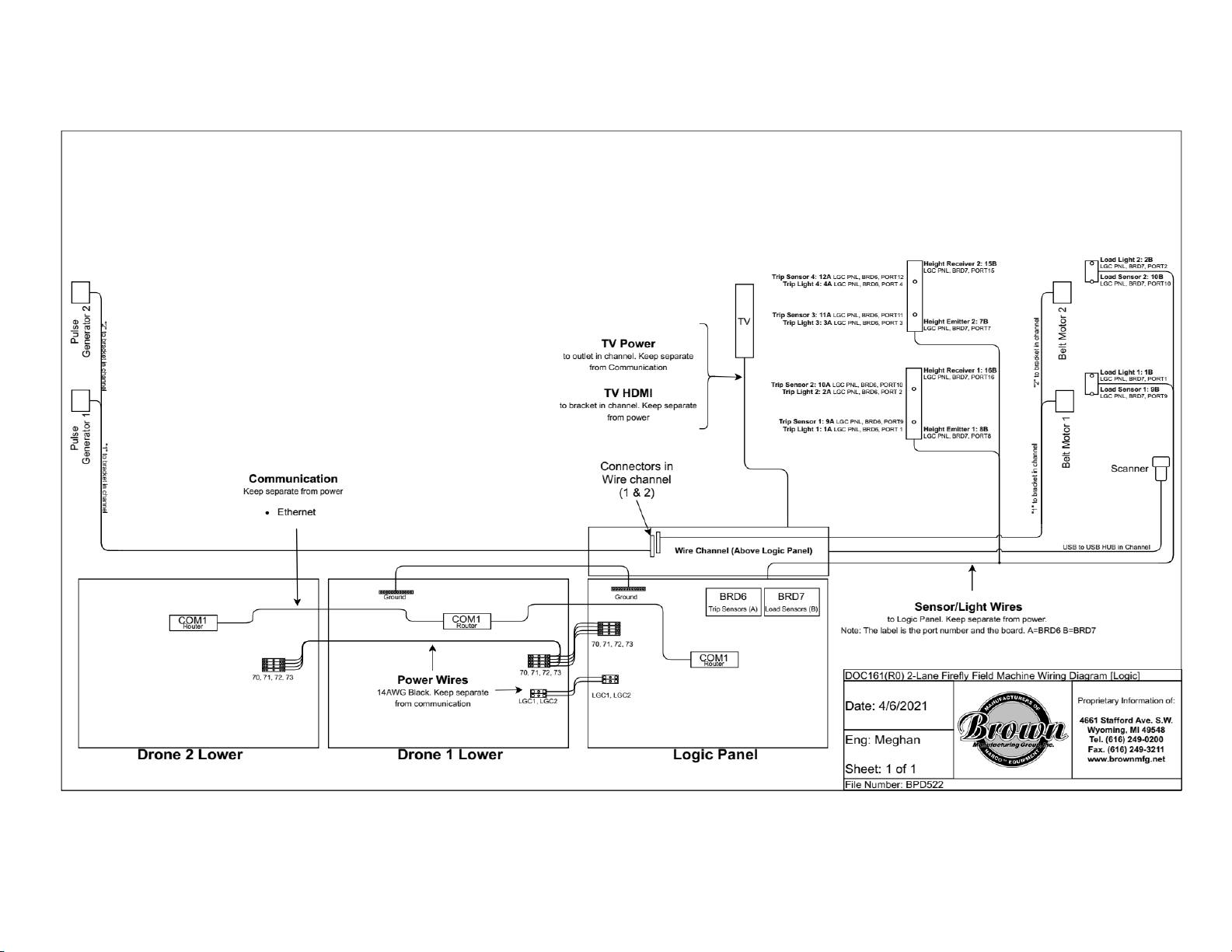
Assembly Step 9: Wire Machine
The machine has several internal connections between
components that are disconnected for shipping, and must
be reconnected to finish installation. Due to the technical
nature of these connections, it is recommended only a
Brown Technician perform the final wiring operations.
Please refer to Appendix A for machine wiring
diagrams.
4

BrownDigital FireFly set-up guide
Machine Adjustments
Belt Tension
It is normal for a new belt to stretch within the first year
of its life. That is why it is essential to maintain a
centered position. Monitor to see if the belt drifts a
certain direction and the rate at which it drifts. This will
indicate which side of the roller to adjust and the amount
it will need to be adjusted.
The side that the belt drifts towards indicates the side
that needs to be tensioned. The faster a belt drifts, the
more it needs to be tensioned [on the drifting side]. Keep
in mind that it is possible to over tension a belt. To
check, grab the edge of the belt (near one of the rollers)
and try to shift it on the roller. If it cannot be moved, the
belt is over tensioned.
Belt Tracking
Belt tracking is adjusted with the red knobs on the end of
the conveyor frame. Remember, increasing the belt
tension on one side will cause the belt to track towards
the opposite side of the dryer frame. Decreasing the belt
tension on one side will cause the belt to track towards
that side. Additional adjustments may be required when
the oven reaches full temperature or as the belt stretches
with wear.
Load and Object Detectors Adjustment and Cleaning
The load sensors and object detection (trip) sensors
must work correctly for proper operation of the machine.
These sensors send an invisible beam of light to a
reflective target located under the belt. The beam is
reflected by the target and detected by the sensors. A red
light above each sensor is activated when the sensor
detects the target. If the target is not detected when
nothing is blocking the beam, the sensor lenses and
target should be cleaned with a rag. Mild solvents may
be used to clean off stubborn deposits. Sensors must be
pointed at targets, and targets must be located directly in
the line of sight of the sensors.
Height Sensor Adjustment and Cleaning
The height sensors on the Firefly operate in
emitter-detector pairs shown in Figure 1. One sensor
emits a visible red laser beam, while the paired detector
senses the beam. If an object blocks the beam, the
machine stops the belt and alerts the user to a height
sensor error. The height of the beam may be adjusted by
moving the sensors up or down in their mounting slots.
A yellow light on the detector indicates detection of the
emitted beam. The emitter and detector pairs must be
aligned such that the beam is always triggering the
detector when nothing is blocking the beam. It may be
necessary to clean the lenses on the emitter/detector
pairs if foreign debris accumulates on the lenses.
5

BrownDigital FireFly set-up guide
Appendix A
Firefly Machine Wiring Diagrams
6

BrownDigital FireFly set-up guide
Figure A.1: 1-Lane Firefly Machine Wiring Diagram
7

BrownDigital FireFly set-up guide
Figure A.2: 2-Lane Firefly Machine Wiring Diagram
8

BrownDigital FireFly set-up guide
Figure A.3: 3-Lane Firefly Machine Wiring Diagram
9

Brown Manufacturing Group, Inc.
4661 Stafford Ave. S.W.
Wyoming, MI 49548
Phone: 616-249-0200
Fax: 616-249-3211
www.brownmfg.net
User’s Manual
Revision 6
0

Table of Contents
Firefly Operation 1
Home Screen 1
Belt Operations 2
Preheat 2
Start/Stop Job 2
Action Icons 3
Programs and Cure Settings 3
Default Program 3
Creating a Program 3
Loading a Saved Program 4
Editing a Program 5
Deleting a Program 5
Maintenance 5
Creating a Maintenance Task 6
Editing a Maintenance Task 6
Deleting a Task 7
Settings Screen 7
Locks 8
Firefly Drone Software 9
1

BrownDigital FireFly user’s manual
Firefly Operation
The Firefly Dryer allows users to customize pretreat-cure
and print-cure settings to accommodate the varying styles
and types of individual garments.
When the machine turns on, the Firefly software will start
automatically and will display the Firefly’s Home Screen.
This screen will look similar to the one shown below.
Firefly Main Home Screen
A Firefly Dryer can have up to three separate belts. These
belts are often referred to as the Lanes of the Firefly. Each
Lane has its own set of cure parameters, which it uses to
cure the garments placed on the belt. Cure parameters are
displayed on the Home Screen and are color coded to help
users identify a Lane’s corresponding settings.
Color-Coded Lane Settings
Upon software start up, all Lanes will be set to use the
DEFAULT Program. If desired, the user can select the
target temperature and the belt speed for each lane.
Alternatively, the user can load a Program, which
contains pre saved values for all the cure parameters.
More information about creating Programs and
descriptions of Program Settings can be found in a later
section.
Once the cure settings are selected, the user can either
press/scan the barcode above Start/Stop Job to begin
sending garments or press/scan the barcode above Preheat
to warm the dryer prior to sending the garment. After
pressing either of these action barcodes, a message
window will appear with an on-screen number pad. This
is where the user tells the system which Lane number to
perform the action on (preheat or start job). If Preheat is
selected, the dryer will initiate a prewarm cycle and the
bulbs will begin heating up to the selected target
temperature. If Start/Stop Job is selected, the belt will
start moving without initiating a prewarm.
After the belt starts moving, the operator can begin
loading garments. The product has to be loaded within
the edges of the belt. Anything outside of the belt
boundary could catch inside of the dryer leading to a
potential fire. For more information about loading
technique, see “Proper Loading Technique” located in the
Firefly Technicians Reference.
⚠ Warning: The belt will be moving. Operators should
keep any loose hair, clothing, and accessories away from
the belt.
There is a bridge going across the belt located directly in
front of the Heat Chamber. This bridge is sometimes
referred to as the Trip Bar and contains sensors that tell
the system when a garment is about to enter the Heat
Chamber.
Note: for more information on how the trip sensors
operate, see “Object Detection” in the Firefly
Technicians Reference.
If the Start/Stop Job button was pressed instead of the
Preheat button, the prewarm will happen when a garment
is detected at this Trip Bar/bridge. The belt will stop until
the dryer has reached the target temperature. Performing
a Preheat before Start/Stop Job can decrease the amount
of time that the garment has to wait before entering the
Heat Chamber.
Note: The dryer will need to preheat when left idle for a
sufficient amount of time. The prewarm times can be
altered in settings. See “Preheat Settings” in the Firefly
Technicians Reference for more information.
After the dryer has finished preheating, the belt will start
moving and the garment will be sent through the Heat
Chamber. The Belt Speed that is displayed on the Home
Screen is the amount of time that the garment will be
exposed to heat.
The garment will exit on the other side of the dryer where
the operator can remove the garment from the belt.
2

BrownDigital FireFly user’s manual
Home Screen
As mentioned before, the cure settings for each Lane are
displayed on the Home Screen of the Firefly Main
Software. These cure settings are either selected manually
or loaded from a desired Program.
The settings displayed for each Lane are as follows:
●PROGRAM NAME: The name of the loaded
Program that the Firefly is currently using to cure
garments
●TEMP: The target temperature that the Firefly will
reference when curing a garment.
●BELT SPEED: The time a garment will spend in
the Heat Chamber on the corresponding Lane.
There is an expand icon located below each Lane that,
when pressed, will expand additional cure settings. The
screen will look similar to the one shown below when the
additional settings are expanded.
Expanded Program Settings
The parameters available in the expanded view are as
follows:
●CONVECTION TOP*: This controls the
percentage power of the Top Fans, which are
located above the Heat Chamber(s).
●CONVECTION BOTTOM*: This controls the
percentage power of the Bottom Fans, which are
located below the Heat Chamber(s).
●EXHAUST*: This controls the power (represented
in a percentage) of the Exhaust Fan(s), which are
located on top of the Drone(s).
●COOLER*: This sets the power of the garment
Cooling Fan(s).
●BULB POWERS: This lists the percentage of
power for all the bulbs (in the corresponding Lane’s
Heat Chamber).
●PRINT*: If the unit is equipped with the Linx
System, this print button will print the barcode label
for the selected Program.
* Note: Some of these options may not be available. Your
Firefly system may not be equipped with Top Fans, Bottom
Fans, Cooler, or Linx Connection (Print option). If you are
unsure of the features included with your machine, contact
your Brown Manufacturing Sales Representative.
The settings for the fans determine how fast the fan will
spin, which is directly related to the amount of air that is
moved. The fans are beneficial in specific situations, but it
is recommended that they be used in small amounts to
prevent lowering the overall temperature of the dryer.
Note: for more information on fan operation and the effects
the fans have on the dryer, refer to “Convection Top and
Bottom” and “Exhaust and Cooler” sections in
Technicians Reference.
Belt Operations
As mentioned previously, the user can tell the system to do
one of two things to initiate garment curing: preheat the
dryer or start the belt. These actions are controlled by
pressing on (or scanning) the corresponding barcode on the
Home Screen. The belt status for each Lane will be
displayed next to the expand icon and will change
depending on which action barcode is selected.
Preheat
When pressed, the system will initiate a prewarm cycle. The
belt status will update to say Prewarming and then show a
countdown. The countdown represents the remaining
preheat time. When the countdown reaches zero,
“Prewarming” will disappear from the belt status (status
will be blank) indicating the belt is in normal operation and
the operator can begin sending garments.
3

BrownDigital FireFly user’s manual
Start/Stop Job
This barcode only controls belt operation. When pressed
while the belt is stopped, it will begin moving and the belt
status will be blank indicating that it is in normal operation.
Alternatively, if the belt is running and the button is pressed,
the belt will stop and the status will show Job Stopped.
As mentioned earlier, if the operator begins sending shirts
while the dryer is cold, the system will automatically
perform a prewarm cycle when a garment is detected at the
Trip Bar. The belt status will update to show “Prewarming”
and then a countdown. When the countdown reaches zero,
the status will be cleared and the garment will proceed into
the Heat Chamber.
Action Icons
Located in the bottom right corner of the Home Screen are
four icons:
POWER DOWN: Pressing this icon will
initiate a total system shutdown sequence
SETTINGS: This button will redirect the
user to the SETTINGS menu
MAINTENANCE: This button will
redirect the user to the Scheduled
Maintenance page. It will also flash if a
Maintenance Task is overdue. More
information about Maintenance can be
found in the “Maintenance” section.
Another action icon that the user may interact with is the
update icon . This icon will appear towards the bottom
left of the screen, in between the time and the Firefly logo.
This icon indicates that there is a software update available.
It is suggested that the software update is initialized when
the machine is not in operation. To update, press on the icon
and confirm the update. The software will automatically
restart when it has finished installing the update.
4

BrownDigital FireFly user’s manual
Programs and Cure
Settings
A Program is a group of settings that were selected prior
to machine operation and saved under a user specified
name. The cure settings available on the Home Screen,
can be selected and saved as a Program. Programs allow
for smooth transitions when changing cure parameters.
There are seven different cure settings that the user can
use to customize Programs. These were defined at the
beginning of the “Home Screen” section of this
document. As a reminder, the available Program settings
are as follows:
●Temp
●Belt Speed
●Convection Top
●Convection Bottom
●Exhaust
●Cooler
●Bulb Powers
Default Program
When the software first starts, the DEFAULT Program will
be displayed for all three Lanes. This Program can be
altered as necessary and should be set to the parameters
used to cure the majority of the products. To change these
settings:
1. Press
2. Press
3. Alter the settings as desired. The button in the top
right corner will switch to say SAVE when changes
have been made.
Note: if you wish to revert the changes, press RESET in the
top left corner. To exit the screen without making any
changes, press where it says BACK in the top right corner.
4. Press the SAVE button
5. Press HOME to return to the Home Screen
Creating a Program
Creating a Program was designed to be convenient to
users. Any time a cure setting is changed on the Home
Screen, the header that typically displays the Program
Name will switch to SAVE.
Note: changing a parameter does NOT mean that a
Program needs to be saved. The Firefly will use
whichever parameters are selected at the start of a job to
cure a garment.
All of the cure settings mentioned in the Home Screen
section are available to be changed and saved in a
Program.
To change bulb power settings:
1. Expand the additional settings under the desired
Lane
2. Press on the button that says BULB POWERS
3. Press on the percentage next to the desired bulb
4. Use the number pad to type in a percentage
between 0-100% where 0% is off and 100% is
full power.
5. Press to accept the value or to cancel
6. Change other bulbs as necessary using the same
procedure
7. Press to accept all the bulb power changes
Bulb Power Settings
To change any other cure settings:
1. Press on the desired setting
a. Settings include Temp, Belt Speed,
Convection Top, Convection Bottom,
Exhaust, Cooler
2. Enter the value using the on-screen number pad
3. Press to accept the change or press to
cancel
After the user has finished altering settings, they can
press SAVE and enter an applicable Program Name using
the on-screen keyboard.
5

BrownDigital FireFly user’s manual
Reminder: Press to access additional settings that
will be saved as part of the Program.
Keyboard Icons
●: toggles between uppercase and lowercase
letters
●: changes the keyboard to display accented
letters
●: [Backspace] erases a letter/number from the
end
●: cancel without saving and return Home
Loading a Saved Program
There are two different ways an active Program can be
changed for a Lane:
1. Using the shortcut on the Home Screen
2. Navigating to the Program Screen in Settings
Both options will bring the user to the Programs page where
the user can select from a list of previously saved Programs.
Example Programs Page
Keep in mind that once a Program is loaded, the Dryer will
need time to adjust to any changes in temperature, belt
speed, and airflow. For example, a Program is loaded with a
higher temperature than the one it just replaced. The system
will have to initiate a prewarm to reach that temperature
during which garments will not be sent.
Option 1: Program Selection Shortcut
1. Press on the Program Name currently displayed for
the desired Lane
2. Select the new Program Name from the list
a. Use and to navigate to different
pages of saved Programs.
After a Program has been selected, the user will be
redirected back to the Home Screen where the selected
Program will be displayed in the Lane settings. To return to
the Home Screen without selecting a Program, press HOME
in the top left corner of the PROGRAMS Screen.
Option 2: Program Selection from Settings
This option involves a few extra steps, but the user can select
a Program for all the Lanes while in this screen.
1. Press
2. Press
3. Select the desired Program Name from the list
4. Using the on-screen number pad, enter the desired
Lane number to apply the selected Program
5. Press to load the Program or press to cancel
6. As necessary, repeat steps 3-5 for the other Lanes
7. Press HOME in the top left corner
Editing a Program
There are three ways the user can edit an existing Program.
Option 1: Home Screen
Edit the settings directly on the Home Screen. Useful when
trying to edit settings that have already been loaded into the
Home Screen.
1. Change the cure settings on the Home Screen to the
desired values.
2. Press SAVE and type in the same name as the
Program you are trying to edit.
Option 2: Program Selection Shortcut
Edit the settings using the Program selection shortcut.
Useful when loading a different Program and want to
check/change a value before loading it.
1. Press on the Program Name of the currently
displayed settings.
2. Locate the desired Program from the list
3. Press and drag the Program name to
4. The settings will be displayed in the same editing
format as the DEFAULT program
5. Press SAVE after editing the desired values.
6

BrownDigital FireFly user’s manual
After pressing SAVE, the program will automatically be
loaded into the Lane settings and the user will be redirected
to the Home Screen.
To cancel the Program changes, press RESET to return any
edited values to what they were originally and then press
BACK. To return to Program selection without changing
values, press BACK.
Option 3: Settings
Edit the Programs from Settings. This is useful when trying
to edit Programs for multiple Lanes or if the user wants to
edit a Program for future use (does not want to load it into
the Home Screen).
1. Press
2. Press
3. Press and drag the desired Program Name to
4. Edit the values as necessary
5. Press SAVE. The user will be redirected to the
Programs page.
a. Can press RESET then BACK to return to
the Programs page without making changes
6. Press the newly edited Program Name to apply it to
a Lane
7. Enter the desired Lane number then press to load
the Program or press to cancel
8. As necessary, repeat steps 3-5 for the other Lanes
9. Press HOME in the top left corner
Deleting a Program
1. Navigate to the Programs screen by pressing:
a. on a loaded Program Name or
b. →
2. Locate the desired Program
3. Press and drag the Program to
4. A message will appear asking the user to confirm
the deletion of the selected Program. Verify the
correct Program is selected
5. Press YES to delete or NO to return to the Programs
page without deleting
Note: If a currently loaded Program is deleted, the Program
Name and its settings will remain on the Home Screen until
the Program (or its settings) is(are) changed.
7

BrownDigital FireFly user’s manual
Maintenance
Normal wear and tear on the Firefly is inevitable over time.
The maintenance activities outlined in the Firefly
Maintenance Manual are designed to prolong the life of
essential components and keep the Firefly functioning at
optimal efficiency. Since there are multiple maintenance
activities that need to be performed and each at varying
times, the Maintenance feature was designed to help keep
track of upcoming tasks. To schedule or view maintenance
events, press located on the bottom right of the Home
Screen. The Maintenance page can also be accessed by
pressing then on . The Maintenance page
will look similar to the one shown below.
Example Maintenance Page
To return to the Home Screen, press HOME in the top left
corner of the screen.
The Maintenance icon will flash on the Home Screen to
indicate that a task needs to be performed. When the user
presses on the flashing icon, the task that is due will be the
one flashing red on the Maintenance task list. The user can
perform this task then press COMPLETED TASK TODAY
to reset the task countdown.
If the user does not want to implement this feature or would
like to disable task notifications:
1. Press on the Home Screen
2. In the bottom right corner press
a. This will switch the text to OFF indicating
that the notifications are disabled
b. Can also disable all maintenance task
notifications from any of the Task
Scheduling Screens.
3. Press HOME to return to the Home Screen
Notice that will no longer be displayed on the Home
Screen when the notifications are disabled. Even though the
icon is not displayed, the user will still be able to press in
the empty icon box to navigate to the Maintenance page.
The tasks that are due will still flash red on this page even
though the Home Screen notifications are disabled.
Re-enable the notifications by following the same procedure
except press OFF to turn it to ON.
Creating a Maintenance Task
To create a task, press on one of the empty red Maintenance
Slots. The screen will be redirected to look similar to the
one shown below.
Task Scheduling Screen
The frequency is how often the event will occur. To change
this, press on the box next to Frequency. A drop down menu
will appear with the following options:
●Daily
●Weekly
●Monthly
●Quarterly
●Semiannually
●Yearly
Note: Recommended maintenance tasks and frequencies can
be found in the Firefly Maintenance Manual.
Select the date that the task was last performed by pressing
on the currently displayed date next to LAST DATE
PERFORMED and selecting the correct day from the
calendar. If it has not been performed yet, select a future
date that the task should be performed by.
The NEXT SCHEDULED DATE will update automatically
based on the first two responses.
8
Table of contents
Other BROWN Dryer manuals