BRUEL & KJAER 4915 User manual

Instruction
Manual
Digital Stroboscope Type 4913
Fibre-Optic Source Type 4915
1-033
0689-1A
BE-0689
'~~
t.
-~'
,
_:~
·:
•~
=~
i c-i
~":
i -
·-
.i
~
"
Type 4913 Is a combined
Stroboscope/-
Tachometer
for
visual Investigation and
accurate measurement
of
rapid, repetitive
motion, mechanical resonances, vibration
etc. It Includes a hand-held Lamp Unit
US
0008 and may be triggered from an Int.
generator,
power
llne
or
ext. tachometer sig-
nal
to
provide
a stationary
or
slow moving
Image
of
objects with motion frequency from
5 Hz
to
1OkHz (0,3
to
600 k r/min). ·
separate
modes with adjustable time and phase delay
permit
observation at any required
point
in
the
motion
cycle. In addition a built-In
4-dlglt
display facllltates
direct
reading
of
motion
frequency
or
speed,
time
or
phase delay.
As
extra
Type 4913 can be coupled with the
Fibre-Optic Source Type 4915. This has a
reslllent 1,8 m long
fibre-optic
cable AE 6000
and outputs a convenient point source
of
lllumlnatlon
that
Is Ideal
for
stroboscopic
examination
of
small components, Intricate
mechanisms and microscope specimens.
For Internal Inspection
of
engines and other
machinery, an Endoscope Probe can be
connected.
+
Bri.iel
&
Kjcer


DIGITAL STROBOSCOPE TYPE 4913
AND
FIBRE-OPTIC STROBOSCOPE SOURCE TYPE 4915
From
serial
no
. 968661
and
1021484
respectively
June
1982

SAFETY CONSIDERATIONS
Types 4913 and 4915 have been designed and tested according to Class
II
of
IEC Publication
348, Safety Requirements for Electronic Measuring Apparatus, and have been supplied in safe
condition. The present Instruction Manual contains information and warnings which should be
followed by the user
to
ensure safe operation and to retain the instruments in safe condition.
Special note should be made
of
the following:
APPLICATION OF POWER
Before each use
of
Stroboscope Type 4913, check that it is set to match the available mains
voltage and that the correct fuse is installed.
SAFETY
SYMBOLS
fil The apparatus will be marked with this symbol when it is important that the user refer
to
the associated warning statements given
in
the Instruction Manual.
.l
Chassis terminal
rJ-,
Earth
or
ground terminal
,"//'
Hazardous voltage
WARNINGS
Keep Types 4913 and 4915 well away from volatile liquids and gasses and operate only in well
ventilated environments.
Whenever
it
is likely that the
correct
function
or
operating safety
of
one
or
other
of
the
instruments has been impaired, they must be made inoperative and be secured against
unintended operation.
Any internal adjustment, maintenance
or
repair
of
the instruments must be avoided as far as
possible and, if unavoidable, must be carried out only by trained service personnel.

CONTENTS
1.
INTRODUCTION
AND
SPECIFICATIONS
(Product
Data)
............................................................................. 1
2.
CONTROLS
................................................................
..
.............................................................................................. 3
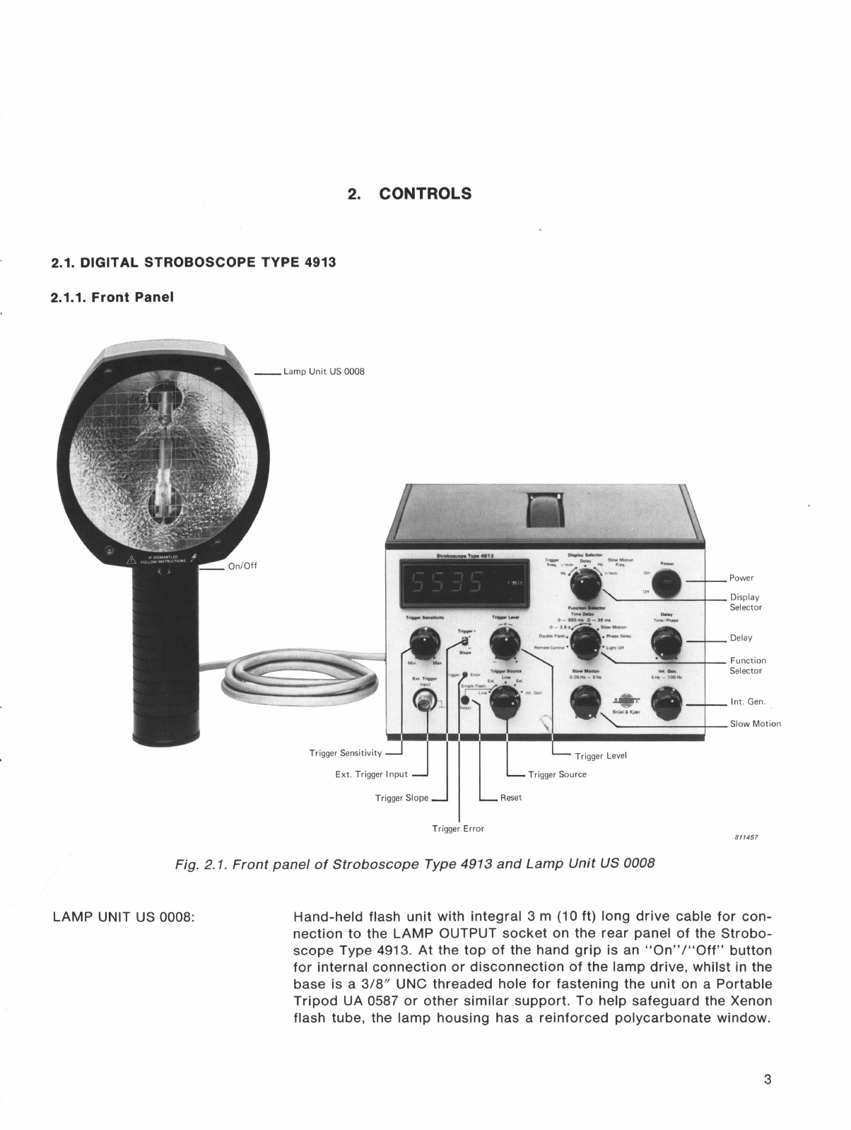
2.1. DIGITAL STROBOSCOPE TYPE 4913................................................................................ 3
Front Panel ......................................................................................
..
..................................... 3
Rear Panel ..............................................................................................................................6
2.2. FIBRE-OPTIC STROBOSCOPE SOURCE TYPE 4915
..
...........................
..
...................... 8
3.
OPERATION
WITH
HAND-HELD
LAMP
UNIT
US
0008.................................................................................. 9
3.1
. PRELIMINARY ........................................................................................................................9
Environment and Handling................................................................................................... 9
Mounting ................................................................................................................................. 9
Connection
of
Mains Supply ............................................................................................. 10
3.2. OPERATION AS A "FREE-RUNNING" STROBOSCOPE ..............................................
11
Determination
of
Motion
Frequency
or
Speed ...............................................................
11
Determination
of
Phase Delay
or
Lag.............................................................................. 13
Timing
of
Motion
Sequences and Events........................................................................ 14
Slow-Motion
Observation................................................................................................... 14
3.3. OPERATION FROM EXTERNAL TRIGGER SOURCE .................................................... 15
External Instruments ...........................................................................................................
15
Photoelectric Tachometer Probe
MM
0012 ..................................................................... 16
Magnetic Transducer
MM
0002 ......................................................................................... 17
3.4. USE WITH LINE TRIGGER SOURCE ...............................................................................
17
3.5. USE WITH DOUBLE FLASH IGNITION ............................................................................ 18
3.6. USE WITH SINGLE FLASH IGNITION .............................................................................. 18
Local and Remote Activation ............................................................................................ 18
Flash
Photography
............................................................................................................... 18
3.7. USE WITH AUXILIARY LIGHT SOURCE.......................................................................... 19
3.8. REMOTE CONTROL ...........................................................................................................
21
4.
OPERATION
WITH
FIBRE-OPTIC
SOURCE
TYPE
4915..............................................................................22
4.1. PRELIMINARY ......................................................................................................................
22
Environment and Handling.................................................................................................
22
Connections
and Mounting................................................................................................
22
Use and
Care
of
Fibre-Optic
Cable AE 6000 .................................................................
23
4.2. NORMAL SINGLE AND REPETITIVE FLASH OPERATION...........................................
24
4.3. SINGLE
"PHOTO"
FLASH OPERATION..........................................................................
24
Triggering .............................................................................................................................
24
Flash
Photography
...............................................................................................................
25

5.
SERVICE
AND REPAIR.........................................................................................................................................26
5.1. GENERAL..............................................................................................................................26
5.2. REPLACEMENT OF FLASH TUBE.................................................................................... 26
Hand-Held
Lamp
Unit US 0008.......................................................................................... 26
Fibre-Optic
Source Type 4915 ..........................................................................................
27

types 4913
and
4915
Digital Stroboscope and Fibre-Optic Source
USES: FEATURES:
•
Investigation
of
repetitive, high-speed
motion
with
engines
and
machines
etc. • Combined
motion
analyzer/tachometer
• Mechanical design, development
and
trouble
shooting
aid
• Slow
motion
frequency
plus
phase
and
time
delay
adjustments
•
Synchronization
with
internal
generator, line or
external trigger source• Resonance search
and
vibration
mode
study
tests
• Stroboscopic
photography
with
time
or
phase
delay •
Automatic
tracking
of
motion
frequency
plus
remote control
•
Internal
inspection
of
machinery
plus
examina-
tion
of
microscope specimens • 4-digit
display
of
motion
frequency/speed, phase-
/time
delay, slow
motion
frequency/speed
The
Brtiel & Kjrer
Type
4913 is a
versatile
instrument
with
the
com-
bined
function
of
stroboscopic
motion
analyzer
and
tachometer.
Using
its
high
intensity
flash source a
station-
ary or slow moving stroboscopic image
of
all
kinds
of
rapid,
repetitive
motion
can be
obtained,
making
it
extremely
easy
to
observe
the
precise
action
and
motion
eccentricities
of
vibration
test
components, engines,
machines
etc.
The
flash
rate
may
be synchronized
with
motion
frequencies from 5
Hz
to
10
kHz
(0,3
to
600 k
r/min)
and
can
be
triggered from
an
internal
generator,
1-0440013-1A
BP
0013
4913
·
--
·;. ··
--::
:.-
_:,:·
.:-~
":=..::.,
..
•·
~-\~...,..-,;,;
• •
ttll"!Ofo
®
,-
rj
·-
• ~
power line
or
external
tachometer
sig-
nal
such
as from a
Photoelectric
Probe
MM
0012
or
Magnetic
Probe
MM
0002.
Separate
modes
with
adjustable
time
and
phase
delay facilitate
measurement
and
observation
at
any
required
point
in
the
motion
cycle
and
a "Slow
Motion"
mode
permits
sub-
jects
to
be viewed
with
an
apparent
motion
frequency
of
0,05
to
5 Hz.
Using
the
built-in
4-digit display
an
accurate
indication
of
motion
frequen-
cy
or
speed,
time
or
phase
delay can be
obtained
which is useful for
both
measurements
and
setting-up
of
the
4915
instrument.
Additional
features are
choice
of
local
or
remote
control, plus
single flash
operation
for photograhic
purposes.
As
an
optional
light
source
Type
4913
can
be coupled
with
the
Fibre-
Optic Stroboscope Source
Type
4915.
Light
transmission
is via a resilient
1,8 m long fibre-optic cable AE 6000
which
outputs
a convenient
point
source
of
illumination
that
is ideal for
stroboscopic
examination
of
small
mechanical components,
intricate
mechanisms
and
microscope speci-
mens
etc.

Furthermore
by coupling
the
light
output
of AE 6000 with a
matching
Endoscope
Probe
as shown overleaf,
inspection
of
internal
surfaces, bear-
LIGHT SOURCE:
Hand-held Lamp Unit
US
0008 with 40 Watt
Xenon-filled flash tube included. Provides
tightly collimated,
cold-light
flash beam and
has integral 3 m long cable plus 3/8/f UNC
tripod
fastening thread
Flaah Duration:
-3
µs
at
half
peak
intensity
Average llluminance:
-17
k lux
at
250 mm
(10 in)
from
lamp, 7 k lux
at
500
mm
(20 in)
and 2 k tux
at
1 m (40 in)
Min. Lamp Life: 75 million single flashes,
or
200 hours
at
maximum flash rate
of
100 Hz
for 50%
reduction
in light
output
FREQUENCY RANGES:
Int. Generator: 5
to
105
Hz
(300
to
6300
r/min)
Ext. Trigger: 0
to
10 kHz (0
to
600 k
r/min)
OPERATING MODES:
Light Off: Flash
ignition
disconnected, but
display operates
for
use as
tachometer
Phaae Delay: 0°
to
360° adjustment, phase
locked
to
Int., Ext.
or
Line
source
Time Delay: 0
to
3,6 s adjustment, synchro-
nized with Int., Ext.
or
Line
source
Slow Motion:
Apparent
motion
frequency
ad-
justable
from
0,05
to
5 Hz (3
to
300 r/min),
synchronized
with
Int., Ext.
or
Line source
Double Flaah: Similar
to
phase Delay,
but
providing double image at complementary
points in
motion
cycle.
At
trigger
frequencies
above
50
Hz, .
repetitive
single flash is
obtained
DISPLAY AND INDICATING MODES:
4-digit LED display, 7-segment numerals
18 mm (0,7 in) high
Trigger Freq: 5
to
9999
Hz
or
300
r/min
to
600 k
r/min
to
within
±0,3
%
+1
digit
LIGHT SOURCE:
Modular
unit
containing 40
Watt
Xenon-filled
flash tube. Includes 1,8 m flexible
Fibre-Optic
Cable AE 6000 and
transmits
a 4,5 mm
diam-
eter
cold-light
flash beam with
radiation
angle
of
approximately
60°
Flaah Duration:
Normal:
-3
µs
Photo:
-150
µs
(half peak intensity):
Average llluminance:
Normal:
-12
k lux
at
25 mm
(1
in) and
1,4 k lux
at
100 mm (4 in)
from
cable
output
Photo:
-so
times
peak intensity
of
normal
mode
Lamp Life:
Normal: -
75
million single flashes,
or
200 hours
at
maximum flash
rate
of
100 Hz
Photo:
-1
thousand single flashes
for
50% reduction in
light
output
ings
and
working mechanisms actually
hidden
inside engines
and
machines
is
possible. A wide range
of
suitable
probes are available from
the
West
Specifications 4913
Delay: 0
to
360° phase delay
to
nearest
de-
gree, Oto 3,6 s
time
delay
to
nearest 0,2
ms
or
better
Slow Motion Freq: 0,05
to
5 Hz
or
3
to
300
r/min
to
within ± 1
digit
EXT. TRIGGER INPUT:
BNT coaxial
socket
for
triggering
via
tachometer
probe
or
external
source
provid-
ing
periodic
electrical signal
Input Voltage: 100
mv
to
30 V Pk-Pk
Input Impedance:
-50
kO
DC
Output:
+8
V (50
mA
max) DC
for
power-
ing an external
tachometer
probe
SINGLE FLASH INPUT:
BNT coaxial
socket
for
remote
activation
of
single flash via
camera
or
electrical pulse.
Single flash synchronized
with
Ext.
or
Line
source and including phase
or
time
delay set
on
instrument is also possible
Input Pulae: +15 V Pk. Minimum
width
2 µs
·
Minimum
Delay: 5
µs
Input Impedance:
-100
kO
SIGNAL OUTPUT:
6-pin
DIN
socket
providing
flash
trigger
and
ignition
reference pulses
for
use
of
Fibre-
Optic
Stroboscope
Source Type 4915
or
Por-
table
Stroboscope
Type 4912 as an
auxiliary
light source
Output Pulses: +15
V,
- 2 ms.
Max. Load:
100
O
REMOTE CONTROL:
Remote selection
of
Light Off, Slow
Motion
or
Phase Delay mode, plus
adjustment
of
Phase
Delay via
6-pin
DIN
socket
·
Specifications 4915
OPERATING MODES:
Normal: as with Type 4913
Photo: manual
or
remote
activation
high in-
tensity single flash via camera flash
contacts
·
or
electrical pulse. Reset
time
-30
s
ELECTROMAGNETIC COMPATIBILITY:
Complies
with Class B
computing
device
of
American FCC (Federal
Communication
Commission) Rules
ENVIRONMENT:
Temperature Range: -10
to
55°C
(+14
to
131°F)
Humidity: o
to
90%
RH
non-condensing
POWER REQUIREMENTS:
via
Stroboscope
Type 4913
DIMENSIONS:
Metal cabinet, excluding
knobs
and feet
German
Companies
Richard
Wolf
GmbH
and
Karl
Storz
GmbH.
For
fit-
ting
the
4915
with
other
fibre-optic
systems, a
blank
coupler is included.
ELECTROMAGNETIC COMPATIBILITY:
Complies
with Class B computing device
of
American FCC (Federal
Communication
Commission) Rules
ENVIRONMENT:
Temperature
Range: -10
to
55°C
(+14
to
131°F)
Humidity: 0
to
90%
RH
non-condensing
POWER REQUIREME.NTS:
100;115;127;200;220;240 V (50
to
60 Hz)
± 10% AC;
45
VA
.
Complies
with Safety Class
II
of
IEC 348
DIMENSIONS:
Control
Unit, excluding
knobs
and feet
Height: 132,6 mm (5,2 in)
Width: 209,5 mm (8,3 in)
Depth: 200
mm
(7,9 in)
(B & K modular cabinet KK 0025,
6/12
of
19n
rack
module)
WEIGHT:
Control Unit: 5,2
kg
(11,5 lbs)
Lamp Unit: 0,8 kg (1,8 lbs)
ACCESSORIES INCLUDED:
1 x Lamp Unit .........................
..
..
.......
.
..
US
0008
1 x
3/8
n
-1
/4n UNC
Tripod
Bush
..
,..... DB 2164
1 x BNC Plug
...
.......................
..
..............JP 0035
2 X BNT Plug .
..
.......
......
..
..
................
~
...
..JP 0315
2 x
6-pin
Plug
..
................................
..
.
....
JP
0601
1 x Camera Flash
Contact
Cable
......
AQ 0375
1 x Power Cable...................
...
'.
.......
..
...
.AN 0020
ACCESSORIES AVAILABLE:
Photoelectric Probe .........
..
..................MM 0012
Magnetic.Probe.
..
...........
..
.
....
.
...
..
..........MM 0002
Height: 132,6
mm
(5,2 in)
Width: 139,5 mm (5,5 in)
Depth: 200 mm (7,9 in)
(B & K
modular
cabinet
KK 0024,
4/12
of
19"
rack
module)
WEIGHT: 2,5
kg
(5,5 lbs)
ACCESSORIES INCLUDED:
1 x
Fibre-Optic
Cable
...
..
..............
......
AE 6000
1 x Output
Coupler
(4,5 mm Dia.)
......
UA 0726
1
~
Blank Output
Coupler
.................... DB 2484
ACCESSORIES AVAILABLE:
Endoscope Probes
are
available
from
Richard Wolf GmbH and Karl Storz GmbH
of
West Germany.
For
details on
your
nearest
Wolf
or
Storz agent, consult your local B & K
representative

2.
CONTROLS
2.1. DIGITAL STROBOSCOPE
TYPE
4913
2.1.1.
Front
Panel
Trigger Sensitivity J
Ext.
Trigger
Input
Trigger Slope
Trigger
Error
\
Reset
Power
____
Display
Selector
Delay
._
______
+-_
Function
Selector
-~-
------+---
Slow
Motion
Int
.
Gen
.
811457
Fig. 2.
1.
Front
panel
of
Stroboscope
Type
4913
and
Lamp
Unit
US 0008
LAMP
UNIT US 0008:
Hand-held
flash
unit
with
integral
3 m (10 ft) long
drive
cable
for
con-
nection
to
the
LAMP
OUTPUT
socket
on
the
rear
panel
of
the
Strobo-
scope
Type 4913.
At
the
top
of
the hand
grip
is an
"On"
/"Off"
button
for
internal
connection
or
disconnection
of
the
lamp
drive,
whilst
in the
base
is a
3/8"
UNG
threaded
hole
for
fastening
the
unit
on a
Portable
Tripod
UA 0587
or
other
similar
support.
To
help
safeguard
the Xenon
flash tube, the
lamp
housing
has a
reinforced
polycarbonate
window.
3

POWER:
DISPLAY SELECTOR:
FUNCTION SELECTOR:
4
SHOCK
HAZARD:
Before
each use
of
the 4913
make
sure
that
the
lamp
drive
cable
is
properly
secured
so
that
it
does
not
become
entangled
with
operating
machinery
which
may
sever
the
high
voltage
drive
lines
of
the cable.
Also
avoid
dismantling
the
lamp
unit
without
first
referring
to
Chapter
5
of
this
Manual,
or
the
separate
Service
Manual
provided.
"On"
/"Off"
switch
for
mains
power.
When
it
is set
to
"On",
the
4-digit
LED
(Light
Emitting
Diode) DISPLAY
of
the 4913
should
light.
5-position
switch
for
selecting
the
following
indicating
modes
with
the
4-digit
LED DISPLAY.
"Trigger
Freq.".
Two
positions
for
display
of
internal
generator
or
external
trigger
frequency
in
"Hz"
or
equivalent
operating
speed in
"r
/min".
With
the
internal
generator
selected
as the
trigger
source,
the
display
range
is
from
5
to
105 Hz
or
300
to
6300
r/min
respectively,
whilst
with
an
external
trigger
source
it
is
from
5
to
10
kHz
or
300
to
600 k
r/min
respectively.
"Delay".
Single
position
for
display
of
phase
or
time
delay
of
the flash
ignition
with
respect
to
trigger
signal.
Display
range
O
to
360° and O
to
3,6
s.
"Slow
Motion".
Two
positions
indicating
the
apparent
frequency
"Hz"
or
speed
"r/min"
of
the
perceived
image
obtained
with
the
"Slow
Motion"
FUNCTION SELECTOR mode.
Display
range
is
from
0,05
to
5 Hz and 3
to
300
r/min
respectively.
8-position
switch
for
selecting
the
following
operating
modes.
"Light
Off". Stand
by
-
lamp
off
mode
with
display
of
phase
delay,
trigger
or
slow
motion
frequency
readout
chosen
with
the DISPLAY
SELECTOR.
"Phase
Delay".
Selects
flash
ignition
with
adjustable
O
to
360°
phase
delay
with
respect
to
trigger
signal.
Permits
stationary
image
of
rotat-
ing and
reciprocating
machinery
to
be
obtained,
which
using
the DELAY
knob
may
be
moved
through
one
complete
motion
cycle. See
section
3.2.2.
"Slow
Motion".
Selects
flash
ignition
synchronized
with
the
fundamen-
tal
(or
sub-multiple)
of
the
trigger
signal
minus
the
frequency
set
with
the
"Slow
Motion"
knob.
Permits
slow
moving
image
of
rotating
and
reciprocating
machinery
to
be
obtained,
whose
apparent
frequency
(or
speed)
may
be
adjusted
from
approximately
0,05
to
5 Hz (3
to
300
r/min)
regardless
of
the
motion
frequency
or
operating
speed
of
the
machinery.
See
section
3.2.4.
"Time
Delay".
Selects
flash
ignition
with
adjustable
"0-36
ms",
"0-
360
ms"
or
"0-3,6
s"
time
delay
with
respect
to
trigger
signal.
Permits
stationary
image
of
rotating
and
reciprocating
machinery
to
be
ob-
tained,
which
may
be
moved
through
part
or
one
or
more
motion
cycles
using
the
DELAY
knob.
The
"Time
Delay"
setting,
may
also
be used in
photographing
of
single
events. See
sections
3.2.3 and 3.6
respectively.

DELAY:
SLOW
MOTION:
INT. GEN:
TRIGGER SOURCE:
"Double
Flash".
Selects
double
flash
ignition
synchronized
with
the
"Line"
or
"Ext."
TRIGGER SOURCE
modes.
It
permits
a
stationary
double
image
of
rotating
and
reciprocating
machine
parts
to
be
ob-
tained
at
two
complementary
points
(ie., 180°
apart)
in
the
motion
cycle
which
may
be
moved
through
one
complete
motion
cycle
using the
DELAY
knob.
When
"Int.
Gen."
is
selected
or
the
frequency
of
the
external
trigger
source
exceeds
aproximately
50 Hz,
operation
is as
with
the
"Phase
Delay"
setting.
See
section
3.5.
"Remote
Control".
Permits
remote
selection
of
"Light
Off",
"Phase
Delay"
or
•"Slow
Motion"
mode
plus
remote
adjustment
of
the phase
delay
via
the
REMOTE
CONTROL
INPUT
socket
on
the
rear
panel
of
the
4913. See
section
3.8.
Single-turn
control
for
adjustment
of
the
phase
or
time
delay
of
the
flash
ignition
with
respect
to
the
trigger
signal. The
range
of
adjustment
is
from
O
to
360° .and O
to
3,6 s
respectively.
For
operation
without
phase
or
time
delay,
the
DELAY
knob
should
be
set
to
its
extreme
anticlockwise
position.
Single-turn
control
for
adjustment
of
the
perceived
slow
motion
fre-
quency
from
0,05
to
5 Hz
or
speed
from
3
to
300
r/min.
10-turn
control
for
adjusting
the
internal
generator
frequency
from
5
to
105 Hz (ie., 300
to
6300
r/min).
5-position
switch
for
selection
of
the
following
trigger
modes.
"Single
Flash -
Line".
Selects
single
flash
ignition
synchronized
with
the
AC
mains
source
used
to
power
the 4913,
but
triggered
manually
via
the RESET
button
on the
front
panel,
or
remotely
via
SINGLE FLASH
INPUT on the
rear
panel. Is
intended
for
photographic
purposes. See
section
3.6.
"Single
Flash -
Ext.".
Selects
single
flash
ignition
synchronized
with
the
EXT. TRIGGER INPUT signal,
but
triggered
manually
via the RESET
button
on
the
front
panel,
or
remotely
via
the
SINGLE FLASH INPUT on
the
rear
panel. Is
intended
for
photographic
purposes.
See
Section
3.6.
"Line".
Selects
operation
as
stroboscope
with
flash
ignition
triggered
by
the
AC
mains
source
used
to
power
the 4913. The
lamp
flashes
at
the
line
frequency
of
the
mains
source.
See
section
3.4.
"Ext.".
Selects
operation
as
stroboscope
and/or
tachometer,
with
flash
ignition
triggered
by
the EXT. TRIGGER INPUT signal. The lamp flashes
in
synchronism
with
the
trigger
signal
at
frequencies
up
to
approxi-
mately
110 Hz. If the
trigger
frequency
exceeds
110 Hz, the
lamp
will
flash in
synchronism
with
the
highest
sub-multiple
of
the
trigger
fre-
quency
below
11
O Hz.
With
no
external
signal
present
at
the
EXT.
TRIGGER INPUT, the
lamp
will
normally
be
kept
extinguished
except
when the
slow
motion
mode
is
employed.
See
section
3.3.
"Int.
Gen.".
Selects
operation
as
free
running
stroboscope,
with
flash
ignition
triggered
by
the
internal
generator
of
the 4913. The
frequency
at
which
the
lamp
flashes
may
be
adjusted
from
5
to
105
Hz
and is set
by
the
INT. GEN. knob. See
section
3.2.
5

RESET:
TRIGGER ERROR:
EXT. TRIGGER INPUT:
Push
button
for
manual
trigger
of
single
flash
ignition
when the
"Single
Flash -
Line"
or
"Single
Flash -
Ext."
TRIGGER SOURCE
mode
is
selected.
A LED
indicator
which
when
lit
warns
that
EXT. TRIGGER INPUT
signal
is absent,
trigger
signal
is
not
periodic
or
TRIGGER LEVEL
knob
is
incorrectly
set.
3-pole
coaxial
socket
accepting
the
standard
BNT
plug
JP 0315
or
BNC
plug
JP 0035
supplied.
The
centre
pin
of
the
socket
is
for
application
of
an
external
signal
to
trigger
the flash
ignition
and/or
use
of
the 4913 as
a
tachometer.
The
middle
contact
(see Fig. 2.2)
outputs
+8
V (50
mA
max.) DC
for
powering
an
active
tachometer
probe
such as
the
B & K
MM
0012,
whilst
the
outer
screen
is
ground
and is
internally
connected
to
chassis. The
trigger
input
has an
input
impedance
of
50
kQ
in
series
with
680 nF and is
triggered
by
signals
between
100
mV
and 30 V
Peak-
Peak
with
repetition
frequency
up
to
10 kHz (6000
kr/min)
and
minimum
pulse
width
of
5
µ..s.
See
section
3.3.
Ext. Trigger
Input--~
Input
Imp
: 50k.Q
Max.
Input
:
30V
Pk-Pk
~----+BV
(50mA
max.)
DC
Tachometer Probe
supply
TRIGGER SLOPE:
TRIGGER SENSITIVITY:
TRIGGER LEVEL:
2.1.2.
Rear
Panel
Chassis
Ground
811358
Fig. 2.2. EXT. TRIGGER
INPUT
(external
view)
2-position
switch
for
selecting
triggering
on
positive
or
negative
going
slope
of
external
trigger
signal
waveform.
Single-turn
control
enabling
EXT. TRIGGER INPUT signal levels
from
approximately
100
mV
to
30 V
Peak-Peak
to
be
accommodated
when
set
for
max. and min.
input
sensitivity
respectively
Single-turn
control
for
adjusting
voltage
at
which
the
4913 is
triggered
by
the EXT. TRIGGER INPUT signal. The
approximate
range
of
adjust-
ment
is -0,4 V
to
+0,4
V
with
TRIGGER SENSITIVITY
set
to
"Max."
and -
30 V
to
+30
V
with
TRIGGER SENSITIVITY
set
to
"Min."
LAMP OUTPUT:
4-pin
insulated
socket
carrying
high
voltage
drive
and
ignition
lines
for
connection
to
the
drive
cable
plug
of
the
Lamp
Unit
US 0008
or
the
LAMP
INPUT
plug
of
the
Fibre-Optic
Stroboscope
Source
Type
4915.
.ffi
WARNING! The
Lamp
Unit
US 0006
supplied
with
earlier
types
of
B & K
stroboscope
is
not
designed
for
operation
with
the 4913 and will
dam-
age
the 4913
if
connected
to
the
LAMP
OUTPUT
socket
SIGNAL OUTPUT:
6-pin
socket
supplying
flash
trigger
and flash
ignition
reference
pulses
for
synchronization
of
an
auxilliary
light
source,
such as the
Portable
Stroboscope
Type
4912
or
the
Fibre-Optic
Stroboscope
Source
Type
4915.
It
accepts
a DIN plug such as
the
B & K
plug
JP 0600
with
screw
lock
provided.
For
connections
see
section
3.
7 and
Chapter
5
respectively.
6

SINGLE
FLASH
INPUT:
_,
100
-
115-127V
:T 1 A
200
-
220
-
240V
:T
O.
SA
Fig. 2.3.
Rear
panel
of
the
Stroboscope
Type 4913
3-pole
coaxial
socket
accepting
the
standard
BNT
plug
JP 0315, BNC
plug
JP 0035
or
Camera
Flash
Contact
Cable
AQ
0375
provided.
Is used
for
remote
trigger
of
single
flash
ignition
using
an
electrical
pulse
or
the
flash
contacts
of
a
camera
as
described
in
section
3.6.
The
identities
of
its
centre
contact
and
double
screen
are
indicated
in Fig. 2.4.
Single Flash
Input
Input
Imp
:
1MS1
Max.
Input:
15V
Chassis
Ground
+15V
DC
Output
(1,5mA
max.)
811357
Fig. 2.4.
SINGLE
FLASH
INPUT
socket
(external
view)
REMOTE
CONTROL
INPUT:
6-pin
socket
with
control
lines
for
remote
adjustment
of
phase
delay
and
selection
of
either
"Slow
Motion"
or
"Light
Off"
modes.
It is
operative
when
the
FUNCTION
SELECTOR
is
set
to
"Remote
Control"
and
accepts
a DIN
plug
such
as
the
B & K
plug
JP 0600
with
screw
lock
provided.
For
connections,
see
section
3.8.
MAINS
VOLTAGE:
FUSE:
AC
MAINS
INPUT:
6-position
switch
for
selection
of
the
correct
mains
voltage
setting
as
described
in
section
3.1.3.
Fuse
holder,
accepting
a 1 A
slow
blow
fuse
(B & K no. VF 0013)
for
100
to
127 V
mains
operation
or
a 0,5 A
slow
blow
fuse
(B & K no. VF 0023)
for
200
to
240 V
mains
operation.
To
check
and
fit
the
appropriate
fuse,
see
section
3.1.3.
2-pin
socket
accepting
the
Power
Cable
AN 0020
provided
for
connec-
tion
of
a 100; 115; 127; 200; 220
or
240 V ± 10% (50
to
60 Hz)
single
phase
AC
mains
supply.
Before
connecting
a
supply,
the
mains
voltage
setting
and
fuse
checks
given
in
section
3.1.3
should
be
carried
out
to
ensure
safe
operation
of
the
instrument.
7

2.2.
FIBRE-OPTIC
STROBOSCOPE SOURCE
TYPE
4915
LAMP
INPUT:
SIGNAL
INPUT:
Lamp
Input
Signal Input
Fibre-Optic Cable
AE
6000
Fibr1!~0P1lC StrOOO.Cope SOUrc:•
1yt)f49H'i
------+----
Man.
'--------+----Ready
.
~--------.1---
Input
----------1----
Light Output
plus
Ball-Lock Coupler
UA
0726
Fig. 2.5. The
Fibre-Optic
Stroboscope
Source
Type 4915
Integral
cable
plus
4-pin
plug
with
screw-lock
for
direct
connection
with
the
high
voltage
lamp
drive
and
ignition
lines
of
the
LAMP
OUTPUT
socket
on
the
4913.
Integral
cable
plus
6-pin
plug
with
screw-lock
for
direct
connection
with
the
flash
trigger
lines
of
the
SIGNAL
OUTPUT
socket
on
the
4913
PHOTO
FLASH
TRIGGERING:
MAN:
READY:
INPUT:
LIGHT
OUTPUT:
FIBRE-OPTIC
CABLE
AE 6000:
8
Push
button
for
manual
trigger
of
single
"Photo"
flash
ignition,
syn-
chronized
with
the
"Int.
Generator",
"Ext."
or
"Line"
TRIGGER
SOURCE
mode
of
the
4913.
For
use
with
the
"Single
Flash -
Ext."
and
"Single
Flash -
Line"
TRIGGER
SOURCE
modes
of
the
4913,
first
press
the
RESET
and
MAN.
buttons
of
the
4913
and
4915
when
the
READY
LED is
lit
and
then
press
the
RESET
button
once
again
to
trigger
flash
ignition.
See
section
4.3.
A LED
indicator
which
when
lit
indicates
that
the
4915
is
charged
and
ready
for
local
or
remote
trigger
of
single
"Photo"
flash
ignition
3-pole
coaxial
socket
accepting
the
Flash
Contact
Cable
AQ
0375
pro-
vided
with
the
4913. Is
used
for
remote
trigger
of
single
"Photo"
flash
ignition
via
the
flash
contacts
of
a
camera
when
the
"Int.
Generator",
"Ext."
or
"Line"
TRIGGER
SOURCE
mode
of
the
4913 is
selected.
See
section
4.3.
24
mm
diameter,
1
mm
pitch
screw
flange
plus
Ball-Lock
Coupler
UA
0726
for
transmission
of
the
light
output
of
the
4915
via
the
flexible
Fibre-Optic
Cable
AE 6000
supplied.
For
use
with
other
types
of
fibre-
optic
cable,
a
Blank
Coupler
DB 2484
is
provided.
See
section
4.1.3.
1,8 m
long,
4,5
mm
diameter
flexible
light
guide.
The
input
face
of
the
cable
(narrow
tapered
end)
push
fits
the
Ball-Lock
Coupler
UA
0726
of
LIGHT
OUTPUT
exit
of
the
4915.
For
clip
fastening
of
an
Endoscope
Probe,
the
output
face
has
a
metal
collar
with
release
catch
attached.
Do
not
sharply
bend
or
twist
the
cable
as
this
can
damage
it.

3.
OPERATION WITH
LAMP
UNIT US 0008
3.1. PRELIMINARY
3.1.1. Environment and Handling
3.1.2. Mounting
The
Stroboscope
Type
4913 plus
its
associated
Lamp
Unit
US 0008
are
designed
to
be
operated
in
environments
with
ambient
temperature
from
-10
to
+55°C
(+14
to
131
°F)
and
humidities
up
to
90%
RH
(non-condensing).
For
safe
operation
avoid
use in
environ-
ments
containing
volatile
gasses
and
liquids.
Also
verify
that
the 4913 is
set
to
match
the
available
supply
voltage
and
that
the
correct
fuse is
installed
before
each use
of
the
instrument.
To
facilitate
easy
adjustment
of
its
controls,
the
4913 is
generally
best
employed
close
to
the
subject
to
be
investigated.
For
this
purpose
a flat,
vibration
free
surface
should be
chosen
where
it
may
be
used
free-standing
without
risk
of
it
falling
into
operating
machinery
or
of
its
lamp
cable
becoming
entangled
with
machine
parts.
To aid
viewing
of
the
instrument
,
its
front
may
be
raised
by
folding
down
the
metal
stand
attached
to
its
front
feet.
0.
•
.,.~IW
tr..,.,,
0-.\
$"-'""""''"""
·-
~:
;;;
•
~
<
M,:,
..
TotMt
O.lir\>
0
:,$1),..i).J•""
-0-,,
..
~
..
S,..,~1
..
.
..
4fl&.0-
.
005tu-5m
Stu-
lOIHl
Fig.
3.
1.
The
Lamp
Unit
US 0008,
plus
Stroboscope
Type
4913
with
front
raised
using
the
metal
stand
on
the
base
of
the
instrument
9

I
Regarding
use
of
the
Lamp
Unit
US 0008
with
the 4913,
this
may
be held
by
hand
or
mounted
on a
tripod
or
similar
support.
A
3/8"
UNC
camera
tripod
mounting
thread
is
provided
in
the
base
of
the
lamp's
hand-grip.
The
Lamp
Unit
provides
a
narrow
concen-
trated
light
beam
and
may
be used
at
a
distance
of
up
to
3
metres
away
from
the
subject
even in
fairly
bright
ambient
lighting
conditions.
The
typical
light
output
characteristics
of
the
lamp
as a
function
of
lamp
-
subject
distance
and angle
of
incidence
from
optical
centre
are
indicated
in Table
3.1
and Fig 3.2
respectively.
Lamp -Subject
0,
125 0,25 0,5 0,75 1,0 m
Distance
Average Flash
25
17 7 4 2
klux
illuminance
811148
Table
3.
1.
Average
flash
illuminance
of
US 0008
as
a
function
of
lamp
-
subject
distance
at
flash
rates
greater
than 50 Hz
Average Flash
illuminance
k lux 8
-
10
0 _ go - 60 _ 40 - 20 +20 +40 +60 +8° +10°
Angle
of
Incidence
from
Optical
Cent
re
8 114
37
Fig. 3.2.
Average
flash
illuminance
of
US 0008 as
function
of
angle
of
incidence
from
optical
centre
with
lamp
-
subject
distance
of
0,5m
Optional
types
of
mounting
for
use
with
the 4913
are
the
Carrying
Case
KA
2004
for
protection
of
the
instrument
during
transport
and the Metal
Frame
KK 0014
for
mounting
it
in a
standard
19 inch
instrumentation
rack.
Both
can
accommodate
two
modular
instruments
the same size as the 4913, however,
for
installation
in the Metal
Frame
the
four
feet
of
the 4913
must
first
be unscrewed. For
further
information
on
rack
mounting
of
B & K
instruments,
the B & K
Short
Form
Catalogue
should be consulted.
3.1.3. Connection of Mains Supply
\
Before
connecting
a
mains
supply, the follow[ng
mains
voltage
setting
and
fuse
checks
should be
carried
out
to
ensure safe
operation
of
the
instrument.
10

Mains Voltage Setting
The 4913
may
be
powered
from
100, 115, 127, 200, 220 and 240 V ± 10% (50
to
60 Hz)
single
phase
AC
mains
lines.
To
select
the
correct
mains
voltage
setting,
use a small
coin
or
wide-blade
screwdriver
to
turn
the MAINS
VOLT
AGE
selector
on the
rear
panel so
that
the
appropriate
voltage
setting
on the
selector
lines
up
with
the
black
arrow
printed
on
the
panel.
Fuse Rating
The
mains
fuse
is
contained
in the fuse
holder
immediately
above
the
MAINS INPUT on
the
rear
panel and
may
be released using a
screwdriver
to
turn
the
centre
of
the
holder.
For
operation
from
100
to
127 V
supplies
the fuse
should
be a 1 A
slow
blow
(B & K no.
VF 0013),
whilst
for
200
to
240 V
supplies
it
should
be
an 0,5 A
slow
blow
(B & K no.
VF 0023).
Make
sure
that
only
fuses
of
the
required
rated
current
and
of
specified
type
are
used
for
replacement.
The use
of
mended
fuses
or
short
circuiting
of
the
fuse
holder
is
prohibited.
Supply Connections
Once
the
mains
voltage
setting
and fuse have been
checked,
the
mains
supply
may
be
connected
to
the
MAINS
INPUT
of
the 4913 using
the
Power
Cable
AN 0020 supplied. The
4913 has a
high
standard
of
safety
insulation
in
accordance
with
safety
class
II
of
IEC 348
and
therefore
its
chassis
need
not
be
connected
to
mains
ground.
3.2. OPERATION AS A "FREE RUNNING" STROBOSCOPE
For
use
of
the 4913 as a
"free-running"
stroboscope,
its
internal
generator
is
employed.
This
type
of
operation
is well
suited
for
quick
investigation,
fault
detection
and
measure-
ments
on
rotating
and
reciprocating
machines
operating
at
a
relatively
constant
frequency.
3.2.1. Determination of Motion Frequency or Speed
For
obtaining
a
stationary
stroboscopic
image
of
a
rotating
or
reciprocating
machine,
plus
determination
of
its
motion
frequency,
the
basic
operating
procedure
is as follows:
1.
Carry
out
the
preliminary
checks
and
adjustments
necessary
(see
section
3.1) and
connect
the
drive
cable
plug
of
the
Lamp
Unit
to
the
LAMP
OUTPUT
socket
of
the
4913.
2.
Set
the
front
panel
controls
of
the 4913 as
follows:
DISPLAY SELECTOR:
TRIGGER SOURCE:
FUNCTION SELECTOR:
DELAY:
SLOW
MOTION:
Trigger
Freq.
"Hz"
or
"r/min"
"Int.
Gen."
"Phase
Delay"
extreme
anticlockwise
position
extreme
anticlockwise
position
11

12
INT. GEN:
extreme
clockwise
setting
POWER:
"On"
The
Lamp
Unit
should
start
to
flash
at
the
frequency
indicated
on
the
DISPLAY
of
the
4913.
If
not,
press
the
"On"
/"Off"
switch
on the
hand-grip
of
the
Lamp
Unit.
3.
Keeping
at
a
safe
distance
which
will
allow
close-up
observation,
aim
the
light
source
at
the
moving
object
to
be
investigated.
4.
Slowly
turn
the INT. GEN.
knob
anticlockwise,
whilst
observing
the
moving
object.
This
will
initially
result
in
multiple
images
being
observed
as
the
flash
rate
is
de-
creased
and
passes
through
synchronism
with
the
multiples
or
sub-multiples
of
the
motion
frequency
of
the
object.
5.
Ignoring
the
multiple
images,
continue
to
turn
the INT. GEN.
knob
anticlockwise
and
stop
the
moment
the
first
stationary
single
image
is
obtained.
When
this
occurs
the
flash
rate
will
coincide
with
the
fundamental
or
one
of
the
sub-multiples
of
the
motion
frequency
of
the
object.
6.
If
it
is
difficult
to
see
whether
the
image
obtained
is a
single
or
multiple
one, then
stop
the
machine
and using
chalk
or
reflective
tape
make
a
contrasting
mark
on the
surface
of
the
object
to
be
examined.
When
the
machine
is
restarted,
commence
turning
the INT. GEN.
knob
from
its
extreme
clockwise
position
until a
stationary
image
with
only
one
contrasting
mark
is
visible.
If
it
is
not
possible
to
obtain
a
stationary
image,
then
the
4913
should
be
triggered
from
an
external
signal
source
as
described
in
section
3.3. The 4913 will then
function
as a
tachometer,
enabling
a
direct
indication
of
the
motion
frequency
up
to
10
kHz
(ie
600 k r
/min)
to
be
obtained.
7.
Having
obtained
a
stationary
image,
note
the
frequency
indication
given
by
the
4913.
To
check
whether
the
indicated
frequency
corresponds
with
the
true
motion
frequen-
cy
and
not
a
sub-multiple,
set
the DISPLAY SELECTOR
to
"Delay"
and the DELAY
knob
to
its
extreme
anticlockwise
position.
Slowly
turn
the
DELAY
knob
to
move
the
image
through
exactly
half
or
one
or
more
whole
motion
cycles
and
note
the
phase
indication
on
the
4913. The
true
motion
frequency
may
then be
calculated
using
the
relation:
where
fm
is
the
true
motion
frequency
in Hz
or
r/min
n is
the
number
of
motion
cycles
f1 is
the
frequency
indication
in Hz
or
r/min
P1 is
the
phase
delay
indication
in
degrees
for
n
motion
cycles
Example:
Frequency
indication
f
1 = 75 Hz
Number
of
motion
cycles
n = 5
Phase
indication
P1 = 18°
True
motion
frequency
fm = 5 x 75 x 360°
18
fm
= 7500 Hz
or
450 k
r/min

An
alternative
method
of
establishing
the
true
motion
frequency
which
may
be
employed
if
difficulty
is
experienced
in
obtaining
a
reliable
motion
cycle
count,
is
to
continue
turning
the
INT. GENERATOR
knob
anticlockwise
until
a
second
stationary
single
image
is
obtained.
The
true
motion
frequency
may
then
be
calculated
using
the
relation:
f =
m (f1 -
f2)
where
f1 is
the
frequency
indication
obtained
with
the
first
stationary
single
image
and f
2 is
that
obtained
with
the
second
stationary
single
image.
Example:
First
frequency
indication
f1 = 75 Hz
Second
frequency
indication
f2 = 50 Hz
75 X 50
True
motion
frequency
fm = 75 -50
f
m = 150 Hz
or
9 k r
/min
3.2.2.
Detemination
of
Phase
Delay
For
examination
of
a
moving
object
at
any
point
in
its
motion
cycle, the
"Phase
Delay"
function
of
the
4913
may
be
employed.
In
addition
the
phase
relation
of
two
or
more
reciprocating
or
rotating
machine
parts
which
have
the
same
motion
frequency
may
be
determined.
1.
Carry
out
items
1
to
7
of
section
3.2.1
to
obtain
a
stationary
single
image
of
one
of
the
synchronously
moving
parts
to
be
examined
and
determine
its
true
motion
frequency.
2.
Using
the
DELAY
knob
move
the
observed
image
of
the
synchronously
moving
part
to
a
convenient
reference
point
in
its
motion
cycle
and
note
the
phase
indication
given
by
the
4913.
3.
Looking
at
the
second
moving
part,
adjust
the
DELAY
knob
to
move
the
observed
image
so
that
it
has
the
same
relative
position
as
the
first
and
note
the
phase
indication
on the 4913.
4.
Provided
that
the
motion
frequency
of
the
two
moving
parts
investigated
is
identical
and
not
greater
than 100 Hz, then the phase
delay
of
the
second
part
with
respect
to
the
first
may
be
determined
by
subtracting
the
first
phase
reading
from
the second. If
the
motion
frequency
is
greater
than 100 Hz, then the
phase
delay
must
be
calculated
using
the
relation:
where
Pd
is
the
true
phase
delay
in
degrees
P1 is
the
first
phase
indication
in
degrees
,
noted
in
item
2
P2 is
the
second
phase
indication
in
degrees,
noted
in
item
3
fi
is
the
frequency
indicated
on
the
4913 in Hz
or
r
/min
fm
is
the
true
motion
frequency
in Hz
or
r/min
13

3.2.3. Timing of Motion Sequences and Events
Using
the
"Time
Delay"
mode
of
the
4913,
motion
sequences
and
events
such as
the
opening
and
closing
of
cam
operated
switch
contacts,
valves
etc.,
may
be
accurately
timed.
The
operating
procedure
for
this
purpose,
is as
follows:
1.
Set
the FUNCTION SELECTOR
to
"O -36
ms
Time
Delay"
and
the
DISPLAY
SELEC-
TOR
to
"Delay".
2.
Keeping
the
control
settings
specified
in
item
1,
carry
out
items
1
to
6
of
section
3.2.1
to
obtain
a
stationary
single
image
of
the
moving
part
or
event
to
be
timed.
3.
Check
that
the
DELAY
knob
is
set
to
its
extreme
anticlockwise
position
and
note
the
relative
position
of
the
end
of
the
motion
sequence
or
event
to
be
timed.
4.
Slowly
turn
the
DELAY
knob
clockwise
to
move
the
observed
image
so
that
the
start
of
the
motion
sequence
or
event
takes
up the
same
position
as in
item
3.
If
this
is
not
possible,
set
the FUNCTION SELECTOR
to
"O -360
ms"
or
"O -
3,6"
time
delay
and
repeat
adjustment
with
the
DELAY
knob.
5.
Note
the
time
delay
indication
given
by
the 4913. This will
correspond
to
the
period
of
the
motion
sequence
or
event,
whatever
the
motion
frequency
of
the
moving
part.
3.2.4. Slow Motion Observation
14
For
determining
the
direction
of
motion
as well as
investigation
of
the
behavior
of
rotating
or
reciprocating
machine
parts,
use
can
be
made
of
the
"Slow
Motion"mode
of
the 4913.
The
operating
procedure
for
this
purpose,
is as
follows:
1.
Carry
out
items
1
to
6
of
section
3.2.1
to
obtain
a
stationary
single
image
of
the
moving
part
to
be
investigated.
2.
Set the FUNCTION SELECTOR
to
"Slow
Motion"
and
depending
on
whether
the
apparent
slow
motion
frequency
or
speed is
to
be
monitored,
set
the
DISPLAY
selector
to
"Hz"
or
"r/min".
3.
The
observed
image
should
now
slowly
rotate
or
move
back
and
forth
at
the
apparent
frequency
or
speed
displayed
on the 4913. The
actual
direction
of
rotation
is
the
same
as
that
of
the
observed
image.
4.
To
alter
the
apparent
slow
motion
frequency
or
speed,
adjust
the
SLOW
MOTION
knob.
Other
uses
of
the
"Slow
Motion"
mode
are
in
determination
of
slip
with
induction
motors
and
friction
coupled
motor
driven
parts
(see
section
3.4),
plus
in
swept
frequency
vibra-
tion
testing
for
initial
and
final
resonance
search
with
mechanical
test
objects.
For
performing
the
latter,
the
4913
should
be set
for
a
slow
motion
frequency
of
approximate-
ly 5 Hz and
its
"Ext."
TRIGGER SOURCE
mode
selected
for
triggering
on
the
output
of
the
frequency
generator
employed
in
the
vibration
test
set-up
(see
section
3.3.1
).
When
the
vibration
test
frequency
is
swept,
a
sudden
increase
in the
displacement
of
the
strobo-
scopic
image
will be
observed
each
time
the
test
object
passes
through
resonance.
Where
initial
.
investigations
indicate
that
more
detailed
examination
is
merited,
it
is
recommended
that
the
vibration
generator
be
set
for
manual
sweep
and
that
the
"Phase
Delay"
mode
of
the
4913
be
employed.
This manual suits for next models
1
Table of contents
Other BRUEL & KJAER Analytical Instrument manuals